EP0120523A1 - Spleissvorrichtung zur mechanischen Spleissverbindung von Textilfäden - Google Patents
Spleissvorrichtung zur mechanischen Spleissverbindung von Textilfäden Download PDFInfo
- Publication number
- EP0120523A1 EP0120523A1 EP84200269A EP84200269A EP0120523A1 EP 0120523 A1 EP0120523 A1 EP 0120523A1 EP 84200269 A EP84200269 A EP 84200269A EP 84200269 A EP84200269 A EP 84200269A EP 0120523 A1 EP0120523 A1 EP 0120523A1
- Authority
- EP
- European Patent Office
- Prior art keywords
- yarns
- twists
- splicer
- yarn
- splice
- Prior art date
- Legal status (The legal status is an assumption and is not a legal conclusion. Google has not performed a legal analysis and makes no representation as to the accuracy of the status listed.)
- Granted
Links
- 239000004753 textile Substances 0.000 title claims abstract description 24
- 238000010168 coupling process Methods 0.000 claims abstract description 17
- 238000005859 coupling reaction Methods 0.000 claims abstract description 17
- 230000008878 coupling Effects 0.000 claims abstract description 7
- 230000009471 action Effects 0.000 claims description 44
- 230000033001 locomotion Effects 0.000 claims description 21
- 210000001520 comb Anatomy 0.000 claims description 16
- 238000006073 displacement reaction Methods 0.000 claims description 9
- 230000000694 effects Effects 0.000 description 5
- 238000000034 method Methods 0.000 description 5
- 206010042674 Swelling Diseases 0.000 description 2
- 230000005540 biological transmission Effects 0.000 description 2
- 230000001276 controlling effect Effects 0.000 description 2
- 230000008569 process Effects 0.000 description 2
- 238000005096 rolling process Methods 0.000 description 2
- 230000008961 swelling Effects 0.000 description 2
- 230000015572 biosynthetic process Effects 0.000 description 1
- 230000006835 compression Effects 0.000 description 1
- 238000007906 compression Methods 0.000 description 1
- 230000003750 conditioning effect Effects 0.000 description 1
- 238000010586 diagram Methods 0.000 description 1
- 239000011888 foil Substances 0.000 description 1
- 210000004209 hair Anatomy 0.000 description 1
- 230000003993 interaction Effects 0.000 description 1
- 230000035515 penetration Effects 0.000 description 1
- 230000001105 regulatory effect Effects 0.000 description 1
- 238000010008 shearing Methods 0.000 description 1
- 230000007480 spreading Effects 0.000 description 1
- 238000004804 winding Methods 0.000 description 1
Images




Classifications
-
- B—PERFORMING OPERATIONS; TRANSPORTING
- B65—CONVEYING; PACKING; STORING; HANDLING THIN OR FILAMENTARY MATERIAL
- B65H—HANDLING THIN OR FILAMENTARY MATERIAL, e.g. SHEETS, WEBS, CABLES
- B65H69/00—Methods of, or devices for, interconnecting successive lengths of material; Knot-tying devices ;Control of the correct working of the interconnecting device
- B65H69/06—Methods of, or devices for, interconnecting successive lengths of material; Knot-tying devices ;Control of the correct working of the interconnecting device by splicing
-
- B—PERFORMING OPERATIONS; TRANSPORTING
- B65—CONVEYING; PACKING; STORING; HANDLING THIN OR FILAMENTARY MATERIAL
- B65H—HANDLING THIN OR FILAMENTARY MATERIAL, e.g. SHEETS, WEBS, CABLES
- B65H2701/00—Handled material; Storage means
- B65H2701/30—Handled filamentary material
- B65H2701/31—Textiles threads or artificial strands of filaments
Definitions
- This invention concerns an improved splicer device to spli- .ce textile yarns mechanically.
- the invention concerns a device suitable for splicing two yarns by disassem- .bling and recomposing the twists in the yarn, the whole being .obtained mechanically.
- Splicer devices using air which employ a turbul- .ence chamber within which the fibres of the yarns are disassem- .bled and intermingled so that a splice of the yarns is obtained.
- CSIRO Europe-an Patent 81301964.3
- a further disadvantage of this device lies in the fact that the remaining tails after the tail ends have been plucked .off are not properly tapered and are therefore ill adapted to- .good cooperation between the fibres of the two yarns in the .area of such remaining tails.
- the means which perform the untwisting and retwisting consist of a pair of untwisting and retwisting rings and of a pair of retwisting disk means. These latter disk means act within the rings but only in the retwisting phase.
- this device provides means to clamp the twists in the tract placed between clamping means in the inner disks and the outer periphery of the rings when the latter are slackened off.
- the slackening of the outer rings becomes necessary so as .to obtain a plucking apart and/or tearing of the tail ends in .such a way that the remaining tails are formed substantially .within a zone lying between the opposed facing untwisting and. .retwisting rings.
- the means to clamp the negative twists imparted to the .yarns serve purposely to prevent the loss of the negative twists .in the tracts of yarn not to be plucked and/or torn at the mo - ment when the rings are opened.
- Another disadvantage of the known cited device consists . .of the fact that the device does not enable tail ends to be obtained with certainty which are perfectly free of twists befo- .re undergoing the plucking and/or tearing action.
- a further disadvantage of the known device lies in the fact that the means which perform the plucking and/or tearing. of the tail ends do not carry out this action in a direction. substantially along the axis of the yarn. As a result it is . .impossible to obtain perfect remaining tails since a plucking. and/or tearing action which is not axial can lead to breakages .or faults in the fibres.
- Yet another disadvantage of this known device lies in the .fact that the position of the remaining tails within the devi- .ce after the plucking and/or tearing action is not controlled. .at the beginning of the retwisting phase.
- Such positioning entails imperfect cooperation between . the fibres of the remaining tail and the fibres of the other .whole yarn, so that the ends of the splice are thus not per- . fect.
- the present invention provides means .able to ensure that substantially no twist is present, after the outer rings have been slackened off, in the tract of the .tails affected by the plucking and tearing.
- this condition is obtained by .providing auxiliary means to balance the twists.
- auxiliary means to balance the twists.
- Such means can .consist, for instance, of grippers or other means able to clamp .the yarn and located at a suitable distance from the outer periphery of the rings.
- the invent- .ion envisages that the tail end itself is tensioned. This can. .be done by a suitable movement of the means which balance the. twists.
- tail ends then undergo an action of plucking and/or tearing by suitable means so as to obtain tapered remaining tails
- the present invention envisages plucking and/or tearing .means exerting an action substantially along the axis of the . .yarn at least momentarily in such a way as to make a plucking. action possible together with axial sliding of the fibres against each other. The breakage of a great part of the fibres . is thus avoided, and suitably reduced remaining tails are the- refore obtained.
- the invention vi- .sualizes the ability to eliminate excessive tail ends by a shearing action alone or perhaps together with a plucking and/ .or tearing action.
- the device of the invention envisages means to bring the .remaining tails together, such means consisting, for instance, of pairs of comb means or equivalent means able to bring the .remaining tails tcgether with the whole yarn with which such . remaining tails have to cooperate.
- the fibres of .the two yarns at the start of retwisting can cooperate closely .in the zone with the remaining tails without any risk of a .wrong winding effect which would lead to the superimposition . .of the remaining tail on the whole yarn.
- the present invention envisages advantageous- .ly the ability to regulate the phases of momentary action of .
- the auxiliary means cited earlier that is, the means intended .to balance the twists in the tracts of yarn affected by the plucking action and the means intended to bring together and to control the remaining tails and the whole yarns.
- the device can be adapted to every kind of .yarn by merely regulating, for every quantity of negative .twists imparted to the yarn, the phase of momentary action of. such auxiliary means that balance the twists.
- actuation means consisting substantially of cams acting .within the arc of one revolution of the shaft from which the . .device gets its motion.
- One revolution of such shaft corres-. .ponds to one complete cycle of splicing of yarns.
- the invention is therefore embodied with an improved spli- .cer to splice textile yarns mechanically, the splice being ob- .tained by coupling two single untwisted yarns and reapplying . .the twists thereafter, part of such single yarns being untwist- .ed until twists of a sign opposite to the original twists have .been imparted, such part then being doubled and remaining tails .being obtained, the doubled tract being then retwisted by im-. .parting a required value of twist, which splicer comprises: .
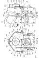
- a splicer 10 has a bearing frame 11, here. substantially U-shaped and consisting of a base 111 and two sides 211 and 311, on which the various components are fitted-and positioned.
- the device 10 At its front and back the device 10 has shields 12 and 112 .(see Figs.4) and two support casings 13 and 113 respectively.. .
- the shields 12-112 comprise positioner notches 212, which .are suitably shaped and serve to enable two yarns to be insert- .ed and positioned in the device 10.
- Positioner rods 312 (Fig. .4b) can be included in cooperation with the positioner notches .212.
- the device 10 can include means to discharge. .the yarn, which are known in themselves and therefore not shown .here.
- Such discharge means can be within the device 10 and be .therefore actuated advantageously by the device itself or be . outside and therefore capable of being actuated easily by the. machine to which the device 10 is fitted.
- Yarns 70-71 are introduced into the device 10 through the positioner notches 212 so that they become positioned between .plate means 14 and 15, which are open at the start of the spli- .cing process; in the example shown the yarns 70-71 are posit-. .ioned substantially parellel.
- the yarns 70-71 are located substantial- .ly parallel to each other, as is shown in the figures, but if. .so required, they can also be positioned crossed over each .other or awry.
- the motion arrives in a known manner with the required characteristics through a motion-input wheel 16 having an axis .of rotation 17.
- This motion-input wheel 16 transmits rotation .to a drive cam 18 and a cam 19 coaxial with the drive cam 18 . .(see Fig s .2).
- the drive cam 18 comprises three paths or .tracks, namely a path 118 to cause pressure of plate means, a .second path 218 to actuate plucking and/or tearing gripper .means and a third path 318 to cause rotation of the plate means respectively.
- This latter path 318 is located at the front on a face of .the cam 18, as shown in Fig2c, and acts on a stud 120 (Fig.2c) .of a lever 20 which rotates plate means and which oscillates . .on an axis 21.
- the lever 20 which rotates plate means includes a toothed segment 220 that meshes with a gear wheel 22 of the plate 15.. .
- the gear wheel 22 then transmits its motion by means of motion-transmission means 23, which have an axis 24 of rotation and. consist in this case of a shaft 123 and toothed segments 223, to a transmission gear wheel 25 and thence 25 to a gear wheel. 26 solidly fixed to the plate 14.
- the device 10 comprises a group 27 to regulate untwisting which consists of a cam 127 that cooperates with a pin 227 so- .lidly fixed to a selector 327.
- the selector 327 can be secar- ed, by rotation on the axis 28 of the plates 14-15, at any re- . q russiad point within a given angular displacement 30 (see Fig.. .4a) by acting on locking means 427.
- the selector 327 serves to determine the moment at which. othe plate, or plate means, 15 has to move lengthwise towards . .the plate means 14 so as to start the untwisting action on the single yarns, and also serves to determine the moment at which the plate 15 has to retreat so as to end the retwisting action ,on the spliced yarn.
- the sequence of gears 22-223-25-26 causes the plate means . 1 4 to rotate in the opposite direction to the plate means 15..
- the path 29 serves to make the plate means 15 approach .the plate means 14 and, in this example, to carry out part of. the mutual interactions of the plate means 15 and 14.
- the path 118 of the cam 18 acts on a stud 131 on a lever. .31 which can rotate about a pivot 231.
- This lever 31 together .with a stud 331 acts on a hollow 126 cooperating with the stud . 331 and present in cooperation with the gear wheel 26 solidly. .fixed to the plate means 14. This fact enables the plate means .14 to move lengthwise on its axis 28 according to the condit-. .ionings provided by the path 118..
- Fig.1 and in greater detail in Figs.3 are shown the plucking and/or tearing means 32-132, which are called hereinafter the grippers 32-132 for the sake of brevity.
- the grippers 32-132 of the invention as we said above, . .can be displaced advantageously at least momentarily in a di-. .rection substantially axial to the yarn as well.
- the steps in the movements of the grippers 32-132 include substantially the following:
- the movements in directions crosswise and axial to the .yarns 70-71 are performed by means of different drive means.
- the crosswise movement is actuated by a U-shaped lever 33, which is pivoted at 333 (Fig.2b) and is operated by the path - .218 of the cam 18, which acts on a stud 133 of the lever 33.. .A control pin 233 acts in a slot 134 of a lever 34 rotatably connected at 35 to a gripper body 36 (see Figs.3).
- the gripper body 36 is rotatably connected at 136 by a .fork means 37 to a pivot 237 able to rotate in its turn around an axis 137. In this way the gripper 32 or 132 can rotate about .two axes 136 and 137 which are substantially at right angles . .to each other.
- the method of working is as follows.
- the gripper 32-132 .which is initially in a position of rest (Fig.3a), is brought. .to a position to engage an excessive tail end 171 (Fig.3b) .owing to the action of the control pin 233.
- the lever 34 abuts against a stop 39, and a further dis-- .placement of the pin 233 causes rotation of the lever 34 about .the pivot 35 together with the lowering of a protrusion 40 . which becomes engaged by a hook means 41 with a spring 141.
- the lever 34 causes closure of a slidable jaw 42 by means of a pivot 142 with a resilient ring 242, which acts on the .slidable jaw 42.
- a pivot 142 With a resilient ring 242, which acts on the .slidable jaw 42.
- the slidable jaw 42 is guid- .ed by means of a slot 342 cooperating with a pin 442, which is .solidly fixed to the gripper body 36 and also acts as a pivot. for the hook 41.
- a nut 542 prevents mutual disengagement of the hook 41 and jaw 42.
- the resilient yielding of the ring 242 determines the gripping force applied to the excessive tail end 171.
- Axial plucking action is operated by the cam 19 (Fig.3c; see also Fig.2a) which, by acting on a stud 243, causes the . opening of two wings 43-143 rotatably anchored at 44-144 res-. pectively on the side frame 311, and also on the side frame . 211 which has been omitted in the figure (see also Fig.2b).
- the wing 143 is operated directly by the stud 243 and itself operates the wing 43 by means of a stud 343 cooperating with a slot 443 in the wing 43 itself.
- These wings 43-143 act on the bodies 36 of the grippers 32-132 respectively and cause their movement 45 outwards substantially along the axis of the coupled yarns 70-71.
- the gripper 132 comprises a projection 48 intended to cooperate with a lever 148 that actuates combs (see Figs.1 and 2a).
- Figs.4 show means 55 which equilibrate the twists.
- a cam 116 made in cooperation with the motion-input wheel 16 has a path 49 obtained on a plate 149 adjustable by means of locking means 249 and also has a stationary path 50, these two paths 49-50 being positioned in sequence.
- the cam 116 acts on a stud 151 of an arm 51 rotatably an- .chored at 251 on the side frame 311.
- This arm 51 in its turn - actuates, with a pin not shown here, an arm 52 rotatably anchored at 152 on the side frame 311.
- the end, or jaw,255 of the lever 355 faces a slidable block 56 guided by a pin 156 cooperating with a slot 256 in the block 56 and with a return spring 57.
- the tail end 170 or 171 of the yarn 70 or 71 becomes po- pitioned between such end 255 and the block 56, the twists in. the tail end 170-171 having to be equilibrated as specified earlier in this description.
- the adjustable plate 149 enables the momentary position of action of means 55 that clamp the twists to be determined.
- the path 49 acts on the stud 151 and causes rotation of the arms 51-52 against the action of the returnspring means 53.
- the tail end 170 or 171 of yarn which was located initially between the end 255 of the lever means 55 and the block 56,. now becomes gripped between 255 and 56.
- the path 50 enga-. ges the stud 151, the arms 51-52 rotate further, and with them- the levers 355, which thrust with their ends 255 against the blocks 56.
- the tail ends 170-171 are now put under tension, . this tension being made axial by the abutment formed with the edge of the positioner notch 212; the tail ends 170-171 also undergo an action of prior plucking which facilitates the subsequent operation of the plucking and/or tearing means 32-132.
- the tensioning of the tail end 170- . 1 71 has the purpose of enabling the twists to be equilibrated. .as between the zone extending from the outer periphery of the. . untwisting and retwisting rings 58-59 to the point of engagement of the yarn between the end 255 of the lever and the block . 56 and the zone extending from the outer periphery of the rings 58-59 to the inner clamping means 78.
- the axial . tensioning it is possible for the axial . tensioning to be carried out by providing a direct axial action .of the lever means 55 on the tail ends 170-171 instead of the. .cited axial action owing to the effect of the abutment at 212. .against which the tail end 170-171 presses.
- this length will determine the number of controlled twists imparted to such tract of tail end 170-171, by .itself or in cooperation with the adjustment of the momentary. .action of the lever means 55 as described above.
- the cam 116 actu- .ates the opening of the means 55 that equilibrate twists. In. .this way the tail ends 170-171, being free of twists, remain . .engaged by the grippers 32-132 alone. The plucking and/or tearing operation and discharge of excess tail ends 170-171 can then take place.
- Figs.5 show details of the plate means 14 and 15. These . plate means 14-15 can be the same as each other or have differ- .ent special characteristics and/or dimensions.
- the dimensions of the plate means 14-15 and their special characteristics (of the ring means 58-59 and retwisting disk . means 60-61) can also vary with variations in the type of yarn .and/or mean length of the fibres.
- Both plate means 14-15 comprise advantageously an untwist- .ing-retwisting ring means 58-59 respectively and a retwisting. .disk means, or disk, 60-61 respectively.
- the ring 59 is embodied in cooperat- .ion with and solidly fixed to the disk 61.
- the ring means 58-59 and disks 60-61 are equipped with means which prevent their rotation and involuntary detachment. in relation to their shells 64-65.
- radial swellings 62 prevent undesir- .ed rotation of the ring 58, being engaged in recesses 63 in the .shell 64 (see Figs.1 and 2a); a stepped portion 158 prevents . disengagement of the ring 58 (Fig.5b).
- Screws 66-166 and 67-167 prevent rotation and detachment. of the disks 60 and 61 respectively, the heads of these screws being sunk in the disks 60-61 respectively, and the screws 66-166 and 67-167 being engaged in the shells 64-65 respectively.
- the disk 60, ring 58 and disk 61/ring 59 assemblage are . kept in position by resilient means, here consisting of compression springs,68.
- the retwisting means, or disks, 60-61 can be flat as in . Fig.5a or be equipped with specialized processing means 69 ac - cording to specific requirements, as in Fig.5c.
- Such proces-. sing means 69 in this case are conformed advantageously with . .stripes having a development in one half opposite to that of . ,the other half of the retwisting means 61, the stripes here having a spiral form.
- These stripes will be advantageously such as to comprise. paces between one processing means 69 and its neighbour, the . .spaces being such that they make clear a lengthwise drawing .action on the fibres and outer hairs of the yarns 70-71.
- the retwisting means 60 and/or .61 contain means 72-73 to couple yarns and also inner means 78 .to clamp the central tract of the yarns 70-71.
- the means 72-73 .to couple yarns are provided in any required position within . .the inner periphery of the rings 58-59, their position possibly being adjustable.
- the inner clamping means 78 of the invention can be obtained in cooperation with the yarn-coupling means 72-73, as shown in the figure, or can be envisaged as being separate without . .departing thereby from the scope of the invention.
- the invention may possibly envisage the ability to regulate the extreme positions of such inner clamping means 78.
- the means 72-73 to couple yarns consist, in this case,of. .pairs of pins, this term being used from now on for the sake of brevity.
- the inner clamping means 78 consist. of a flat end surface of a pin support 172 (see Figs.5d, 5e and .5f), which engages the yarn against the retwisting disk means. .61.
- the latter can include raised portions 178 coinciding with .the area for clamping the yarns and facing and opposed to the. .surfaces 78.
- the pins 73 are solidly fixed to the disk 61 and can move .therewith in an axial direction too.
- the pins 72 together with the pin supports 172 including the inner clamping means 78 are .secured to a circular plate 74 solidly fixed to the shell 64,. and there is therefore a relative axial displacement as between .the pins 72 and the disk 60 when the mutual axial positions of .the shell 64 and disk 60 are varied.
- pairs of pins 72 and/or 73 retractable within supports 172 of .the disk 61. In this case it will not be necessary to have .circumferential hollows 77 and/or 76.
- pins 72-73, or equivalent means independent of the .disks 60-61 and having any required momentary action on the yarns.
- the plate 14 also includes means 75 to bring the remain- .ing tails together. According to the invention these means 75. .to bring the tails 270-271 together can be visualized as coop- .erating with the plates 14 and/or 15 or can be outside the pla- .tes 14-15 and acting momentarily between separated disks 60-61 and rings 58-59.
- Such means 75 in this example consist of combs. These .combs are normally closed (position 75A in Fig.5a) and are .opened by the action of the projection 48 6f the gripper 132 . .on the lever 148 before the excessive tail ends 170-171 are plucked and/or torn.
- Fig.6 shows in particular the combs 75 arranged so as to .counterrotate on the same axis 375.
- the lever 148 having its pivot at 348 comprises two pins 448 on opposite sides of the pivot 348. These pins 448 are en- .gaged in slots 275 in the combs 75.
- Fig.6 shows how actuation of the lever 148 causes rotation .of the combs 75 through the action of the pins 448 in the slots .275 and thus the opening or closure of the combs 75 themselves, .depending on the direction of such actuation.
- the opening takes place by anti-clockwise rotation of the lever .148 by the projection 48 of the gripper 132 (see Figs.1 and 3), whereas closure takes place through the action of a return spring 248 (see Fig.1).
- Fig.5b shows the phase of introduction of yarns 70-71
- Fig.5d shows the untwisting action
- Fig.5e shows. .the yarn-clamping action
- Fig.5f shows the start of the retwisting action.
- Figs.5 show the plates 14-15 in a direction crosswise to. .the development of the yarns 70-71 as inserted into the device .10, that is to say, the view is that of Fig.1 but from above. .With the yarns thus positioned a rotary motion comes to the motion-input wheel 16. This motion is advantageously continuous but could also be transmitted in a variable or pulsating. manner.
- the pins 72-73 At the end of the untwisting phase the pins 72-73 have brought the'untwisted yarns 70-71 together in the meanwhile, .thus permitting the control of the central zone of the yarns . .70-71, which are substantially parallel and in contact with .each other.
- the pins 72-73 are lodged in circum- .ferential hollows 77-76 respectively made in the disks 61-60 respectively.
- the supports 172 of the pins 72 and also the built-up portions 178, when included, are shaped in such a way that they . .do not interrupt the continuity of such hollows 76-77.
- Fig.5e does not show the screws 67-167 so as to keep this .figure clear, but such screws 67-167 press with their heads .against the disk 60 and stop the disk 60 from coming into contact with the disk 61, as we said earlier.
- the yarns 70-71 are clamped in this way by the surfaces . . 78-178 in their central tract located between such means 78 but .are not constrained by the surfaces of the disks 60-61 and .rings 58-59.
- the means 55 to balance twists have, in the meantime, engaged the excessive tail ends 170-171, as is shown diagramma-. .tically in Fig.5e.
- the combs 75 which are already in a circumferential position corresponding with the yarns 70-71 at the end of untwisting, are opened by the action of the projection 48 on the lever 148 and protrude through the circumferential slots 175 in the. disk 6o and ring 58 when the plates 14-15 are pressed against. each other as in Fig.5e.
- the shells 64-65 are in circumferential contact with each other, but the outlets 164 and 165 respectively (see Figs.1 and 2a) permit the action of plucking .and/or tearing the tail ends 170-171, leaving a free passage .for the excess tail ends 170-171.
- the means 79 to block twists constrain against . .the shell 64 the portion of yarns 70-71 not to be torn and .(Fig.5e) prevent the negative twists contained in the tract of .the yarns 70-71 located between the outer periphery of the .rings 58-59 and the inner clamping means 78 from becoming lost .by spreading along the yarns 70-71, through the outlets 164-165 .and outside the rings 58-59 and from being cancelled owing to. .the presence of the positive twists existing outside.
- the clamping action of the inner clamping means 78 has .the effect that the remaining tails 270-271 are tapered from . .a position of greatest thickness near the means 78 themselves. .to an end position near the outer periphery of the rings 58-59.
- the grippers 32-132 carry out the plucking and/or tearing .action, as in Fig.3c, after the opening of the means 55 to ba- .lance twists, and return as in Fig.3d..
- the plucked tail ends 170-171 are discharged by known means when the grippers 32-132 are opened.
- the return of the gripper 132 causes disengagement of the .lever 148 by the projection 48 and a consequent closure of the combs 75, which bring the remaining tails 270-271 close to the yarns 71-70 respectively.
- the combs 75 retreat, in conjunction with the withdrawal. .of the plate 14, to which they are solidly'fixed axially, be-. low the surface of the disk 60 and thus free the remaining .tails 270-271 and yarns 71-70 now lying close to each other. .Thus the yarns 70-71 are now controlled closely along the whole .extent of the disks 60-61 and rings 58-59.
- Fig.5f shows the start of the retwisting phase, the means .78 no longer clamping the yarns 70-71, while the disks 60-61 . .and rings 58-59 press against the yarns 70-71.
- both the ring means 58-59 and the respective retwisting . .disk means 60-61 cooperate in obtaining the required degree of retwisting.
- the conformation and sizes of the rings or ring means, 58-59 and the conformation, sizes and special characteristics of the retwisting disk means, or disks, . .60-61 will vary to suit the mean characteristics of the fibres composing the yarns 70-71 to be spliced.
- the scope and ability of the invention cover the provision .of a differentiated speed of rotation as between one plate means and the other or as between a ring means and a retwist- .ing means.
Landscapes
- Spinning Or Twisting Of Yarns (AREA)
- Yarns And Mechanical Finishing Of Yarns Or Ropes (AREA)
- Treatment Of Fiber Materials (AREA)
- Lining Or Joining Of Plastics Or The Like (AREA)
- Braiding, Manufacturing Of Bobbin-Net Or Lace, And Manufacturing Of Nets By Knotting (AREA)
- Non-Disconnectible Joints And Screw-Threaded Joints (AREA)
- Nonwoven Fabrics (AREA)
- Ropes Or Cables (AREA)
Priority Applications (1)
| Application Number | Priority Date | Filing Date | Title |
|---|---|---|---|
| AT84200269T ATE31909T1 (de) | 1983-03-28 | 1984-02-27 | Spleissvorrichtung zur mechanischen spleissverbindung von textilfaeden. |
Applications Claiming Priority (2)
| Application Number | Priority Date | Filing Date | Title |
|---|---|---|---|
| IT8335783 | 1983-03-28 | ||
| IT83357/83A IT1175076B (it) | 1983-03-28 | 1983-03-28 | Giuntafili perfezionato per la giunzione meccanica di fili tessili |
Publications (2)
| Publication Number | Publication Date |
|---|---|
| EP0120523A1 true EP0120523A1 (de) | 1984-10-03 |
| EP0120523B1 EP0120523B1 (de) | 1988-01-13 |
Family
ID=11320666
Family Applications (1)
| Application Number | Title | Priority Date | Filing Date |
|---|---|---|---|
| EP84200269A Expired EP0120523B1 (de) | 1983-03-28 | 1984-02-27 | Spleissvorrichtung zur mechanischen Spleissverbindung von Textilfäden |
Country Status (11)
| Country | Link |
|---|---|
| US (1) | US4545191A (de) |
| EP (1) | EP0120523B1 (de) |
| JP (1) | JPS59182172A (de) |
| AT (1) | ATE31909T1 (de) |
| AU (1) | AU565250B2 (de) |
| BR (1) | BR8401409A (de) |
| CZ (1) | CZ277727B6 (de) |
| DE (2) | DE3468662D1 (de) |
| ES (1) | ES530675A0 (de) |
| IT (1) | IT1175076B (de) |
| MX (1) | MX157296A (de) |
Cited By (3)
| Publication number | Priority date | Publication date | Assignee | Title |
|---|---|---|---|---|
| WO2007048466A1 (de) * | 2005-10-29 | 2007-05-03 | Oerlikon Textile Gmbh & Co. Kg | Fadenverbindungsvorrichtung |
| CN112093588A (zh) * | 2019-06-18 | 2020-12-18 | 卓郎纺织解决方案两合股份有限公司 | 用于纱线连接装置的摩擦盘 |
| DE102019116487A1 (de) * | 2019-06-18 | 2020-12-24 | Saurer Spinning Solutions Gmbh & Co. Kg | Fadenverbindungsvorrichtung zum knotenfreien Verbinden zweier Fadenenden |
Families Citing this family (5)
| Publication number | Priority date | Publication date | Assignee | Title |
|---|---|---|---|---|
| GB8615636D0 (en) * | 1986-06-26 | 1986-07-30 | Pentwyn Precision Ltd | Pneumatic splicer |
| JP4743475B2 (ja) * | 2004-09-29 | 2011-08-10 | 株式会社シマノ | 釣り竿用竿体及び釣り竿 |
| DE102004051038A1 (de) * | 2004-10-20 | 2006-04-27 | Saurer Gmbh & Co. Kg | Fadenspleißvorrichtung |
| IT201900021060A1 (it) * | 2019-11-13 | 2021-05-13 | Hayabusa S R L | Perfezionamenti ad un dispositivo di giunzione di fili tessili e relativo dispositivo |
| IT201900021258A1 (it) * | 2019-11-15 | 2021-05-15 | Hayabusa S R L | Dispositivo di giunzione di fili tessili e relativo metodo di giunzione |
Citations (3)
| Publication number | Priority date | Publication date | Assignee | Title |
|---|---|---|---|---|
| EP0026253A1 (de) * | 1979-09-28 | 1981-04-08 | Zellweger Uster Ag | Verbindung von Faserverbänden, Verfahren zur Erzeugung der Verbindung und Vorrichtung zur Ausführung des Verfahrens |
| EP0039609A1 (de) * | 1980-05-05 | 1981-11-11 | Officine Savio S.p.A. | Verfahren und Vorrichtung zum Verbinden von zwei gesponnenen Fasergarnen |
| EP0078778A2 (de) * | 1981-11-04 | 1983-05-11 | Officine Savio S.p.A. | Verfahren und Vorrichtung zum mechanischen Verbinden von textilem Garn |
Family Cites Families (7)
| Publication number | Priority date | Publication date | Assignee | Title |
|---|---|---|---|---|
| US3307339A (en) * | 1966-06-27 | 1967-03-07 | Clarence H Porter | Apparatus for joining threads |
| US4170103A (en) * | 1978-03-29 | 1979-10-09 | Wwg Industries, Inc. | Node fixation in self-twist yarn |
| JPS55101560A (en) * | 1979-01-23 | 1980-08-02 | Murata Mach Ltd | Method and apparatus for joining spum yarns |
| CH646208A5 (de) * | 1980-07-23 | 1984-11-15 | Zellweger Uster Ag | Verfahren und vorrichtung zur verminderung abrupten querschnittverlaufs bei der verbindung von faserverbaenden. |
| CH646210A5 (de) * | 1980-07-23 | 1984-11-15 | Zellweger Uster Ag | Verfahren und vorrichtung zur erzeugung einer verbindung von faserverbaenden. |
| EP0078776B1 (de) * | 1981-11-04 | 1986-04-09 | Officine Savio S.p.A. | Spleissvorrichtung zum mechanischen Zerfasern und Wiederzusammensetzen von Garn |
| DE3151270A1 (de) * | 1981-12-24 | 1983-07-07 | W. Schlafhorst & Co, 4050 Mönchengladbach | Verfahren und vorrichtung zum knotenfreien verbinden zweier faeden |
-
1983
- 1983-03-28 IT IT83357/83A patent/IT1175076B/it active
-
1984
- 1984-02-24 US US06/583,393 patent/US4545191A/en not_active Expired - Fee Related
- 1984-02-27 DE DE8484200269T patent/DE3468662D1/de not_active Expired
- 1984-02-27 EP EP84200269A patent/EP0120523B1/de not_active Expired
- 1984-02-27 AT AT84200269T patent/ATE31909T1/de not_active IP Right Cessation
- 1984-02-27 DE DE198484200269T patent/DE120523T1/de active Pending
- 1984-03-16 ES ES530675A patent/ES530675A0/es active Granted
- 1984-03-16 MX MX200708A patent/MX157296A/es unknown
- 1984-03-21 AU AU25965/84A patent/AU565250B2/en not_active Ceased
- 1984-03-23 CZ CS842077A patent/CZ277727B6/cs unknown
- 1984-03-27 BR BR8401409A patent/BR8401409A/pt not_active IP Right Cessation
- 1984-03-28 JP JP59058525A patent/JPS59182172A/ja active Granted
Patent Citations (3)
| Publication number | Priority date | Publication date | Assignee | Title |
|---|---|---|---|---|
| EP0026253A1 (de) * | 1979-09-28 | 1981-04-08 | Zellweger Uster Ag | Verbindung von Faserverbänden, Verfahren zur Erzeugung der Verbindung und Vorrichtung zur Ausführung des Verfahrens |
| EP0039609A1 (de) * | 1980-05-05 | 1981-11-11 | Officine Savio S.p.A. | Verfahren und Vorrichtung zum Verbinden von zwei gesponnenen Fasergarnen |
| EP0078778A2 (de) * | 1981-11-04 | 1983-05-11 | Officine Savio S.p.A. | Verfahren und Vorrichtung zum mechanischen Verbinden von textilem Garn |
Cited By (4)
| Publication number | Priority date | Publication date | Assignee | Title |
|---|---|---|---|---|
| WO2007048466A1 (de) * | 2005-10-29 | 2007-05-03 | Oerlikon Textile Gmbh & Co. Kg | Fadenverbindungsvorrichtung |
| CN101291863B (zh) * | 2005-10-29 | 2012-04-25 | 欧瑞康纺织有限及两合公司 | 纱线连结装置 |
| CN112093588A (zh) * | 2019-06-18 | 2020-12-18 | 卓郎纺织解决方案两合股份有限公司 | 用于纱线连接装置的摩擦盘 |
| DE102019116487A1 (de) * | 2019-06-18 | 2020-12-24 | Saurer Spinning Solutions Gmbh & Co. Kg | Fadenverbindungsvorrichtung zum knotenfreien Verbinden zweier Fadenenden |
Also Published As
| Publication number | Publication date |
|---|---|
| DE120523T1 (de) | 1985-02-28 |
| JPH0446876B2 (de) | 1992-07-31 |
| CZ277727B6 (en) | 1993-04-14 |
| EP0120523B1 (de) | 1988-01-13 |
| AU565250B2 (en) | 1987-09-10 |
| BR8401409A (pt) | 1984-11-06 |
| CS207784A3 (en) | 1992-12-16 |
| AU2596584A (en) | 1984-10-04 |
| ES8502953A1 (es) | 1985-02-16 |
| IT8383357A0 (it) | 1983-03-28 |
| US4545191A (en) | 1985-10-08 |
| ATE31909T1 (de) | 1988-01-15 |
| DE3468662D1 (en) | 1988-02-18 |
| IT1175076B (it) | 1987-07-01 |
| JPS59182172A (ja) | 1984-10-16 |
| MX157296A (es) | 1988-11-11 |
| ES530675A0 (es) | 1985-02-16 |
Similar Documents
| Publication | Publication Date | Title |
|---|---|---|
| EP0140412B1 (de) | Spleissvorrichtungen für das mechanische Spleissen von Textilgarnen, und mechanische Spleissvorrichtung, die derartige Vorrichtungen benutzt | |
| EP0120523A1 (de) | Spleissvorrichtung zur mechanischen Spleissverbindung von Textilfäden | |
| EP1161397B1 (de) | Vorrichtung und verfahren zum führen und schneiden eines zulaufenden fadens beim spulenwechsel | |
| US4139162A (en) | Open-end spinning frame with a device for replacing full bobbins with empty tubes | |
| JPH0221485Y2 (de) | ||
| EP0078778B1 (de) | Verfahren und Vorrichtung zum mechanischen Verbinden von textilem Garn | |
| US4494367A (en) | Splicer device to disassemble and recompose yarn mechanically | |
| DE2361978C3 (de) | Verfahren und Vorrichtung zum Anspinnen einer Offenendspinnmaschine | |
| US4583356A (en) | Splicer device to disassemble and recompose yarn mechanically | |
| US2763899A (en) | Machine for inserting a drawing thread or drawing ribbon in tampons or the like | |
| GB2117419A (en) | Apparatus for the separation and preparing of warp threads for the drawing in of warp threads in healds and dents | |
| US4217938A (en) | Apparatus and method for making dynamoelectric machine windings | |
| DE1257374B (de) | Verfahren und Vorrichtung zum fortlaufenden Aufspulen von Faserbaendern aus Glasstapelfasern | |
| JPH05166657A (ja) | 巻線機 | |
| EP0123329A1 (de) | Spleissverfahren für Fäden | |
| US4915143A (en) | Selectively feeding one of a plurality of weft threads to a gripper projectile | |
| US4792104A (en) | Apparatus for forming yarn transfer tails | |
| JPH0446874B2 (de) | ||
| JPS63136610A (ja) | トロイダルコイルの製造装置 | |
| JPS5950767B2 (ja) | 整経機 | |
| CA1142494A (en) | Apparatus and method for making dynamoelectric machine windings | |
| GB928272A (en) | Improvements in capacitor winding machines | |
| JPS5920535B2 (ja) | 硬貨包装紙供給装置 | |
| JPS6340310A (ja) | トロイダル巻線機 | |
| JPH06156874A (ja) | 糸条の切替巻取方法および装置 |
Legal Events
| Date | Code | Title | Description |
|---|---|---|---|
| PUAI | Public reference made under article 153(3) epc to a published international application that has entered the european phase |
Free format text: ORIGINAL CODE: 0009012 |
|
| AK | Designated contracting states |
Designated state(s): AT BE CH DE FR GB LI LU NL SE |
|
| EL | Fr: translation of claims filed | ||
| 17P | Request for examination filed |
Effective date: 19841126 |
|
| DET | De: translation of patent claims | ||
| 17Q | First examination report despatched |
Effective date: 19860313 |
|
| GRAA | (expected) grant |
Free format text: ORIGINAL CODE: 0009210 |
|
| AK | Designated contracting states |
Kind code of ref document: B1 Designated state(s): AT BE CH DE FR GB LI LU NL SE |
|
| PG25 | Lapsed in a contracting state [announced via postgrant information from national office to epo] |
Ref country code: NL Effective date: 19880113 Ref country code: BE Effective date: 19880113 Ref country code: AT Effective date: 19880113 |
|
| REF | Corresponds to: |
Ref document number: 31909 Country of ref document: AT Date of ref document: 19880115 Kind code of ref document: T |
|
| PG25 | Lapsed in a contracting state [announced via postgrant information from national office to epo] |
Ref country code: SE Effective date: 19880131 |
|
| REF | Corresponds to: |
Ref document number: 3468662 Country of ref document: DE Date of ref document: 19880218 |
|
| ET | Fr: translation filed | ||
| PG25 | Lapsed in a contracting state [announced via postgrant information from national office to epo] |
Ref country code: LU Free format text: LAPSE BECAUSE OF NON-PAYMENT OF DUE FEES Effective date: 19880229 |
|
| NLV1 | Nl: lapsed or annulled due to failure to fulfill the requirements of art. 29p and 29m of the patents act | ||
| PLBE | No opposition filed within time limit |
Free format text: ORIGINAL CODE: 0009261 |
|
| STAA | Information on the status of an ep patent application or granted ep patent |
Free format text: STATUS: NO OPPOSITION FILED WITHIN TIME LIMIT |
|
| REG | Reference to a national code |
Ref country code: CH Ref legal event code: PUE Owner name: SAVIO S.P.A. |
|
| 26N | No opposition filed | ||
| REG | Reference to a national code |
Ref country code: FR Ref legal event code: CD |
|
| REG | Reference to a national code |
Ref country code: GB Ref legal event code: 732 |
|
| PGFP | Annual fee paid to national office [announced via postgrant information from national office to epo] |
Ref country code: GB Payment date: 19950222 Year of fee payment: 12 |
|
| PGFP | Annual fee paid to national office [announced via postgrant information from national office to epo] |
Ref country code: FR Payment date: 19950228 Year of fee payment: 12 |
|
| PGFP | Annual fee paid to national office [announced via postgrant information from national office to epo] |
Ref country code: CH Payment date: 19950303 Year of fee payment: 12 |
|
| PGFP | Annual fee paid to national office [announced via postgrant information from national office to epo] |
Ref country code: DE Payment date: 19950405 Year of fee payment: 12 |
|
| PG25 | Lapsed in a contracting state [announced via postgrant information from national office to epo] |
Ref country code: GB Effective date: 19960227 |
|
| PG25 | Lapsed in a contracting state [announced via postgrant information from national office to epo] |
Ref country code: LI Effective date: 19960229 Ref country code: CH Effective date: 19960229 |
|
| REG | Reference to a national code |
Ref country code: CH Ref legal event code: PL |
|
| GBPC | Gb: european patent ceased through non-payment of renewal fee |
Effective date: 19960227 |
|
| PG25 | Lapsed in a contracting state [announced via postgrant information from national office to epo] |
Ref country code: FR Effective date: 19961031 |
|
| PG25 | Lapsed in a contracting state [announced via postgrant information from national office to epo] |
Ref country code: DE Effective date: 19961101 |
|
| REG | Reference to a national code |
Ref country code: FR Ref legal event code: ST |