EP0120970B1 - Circuit d'acceleration et de deceleration - Google Patents
Circuit d'acceleration et de deceleration Download PDFInfo
- Publication number
- EP0120970B1 EP0120970B1 EP83903111A EP83903111A EP0120970B1 EP 0120970 B1 EP0120970 B1 EP 0120970B1 EP 83903111 A EP83903111 A EP 83903111A EP 83903111 A EP83903111 A EP 83903111A EP 0120970 B1 EP0120970 B1 EP 0120970B1
- Authority
- EP
- European Patent Office
- Prior art keywords
- acceleration
- deceleration
- storage section
- travelling distance
- distance component
- Prior art date
- Legal status (The legal status is an assumption and is not a legal conclusion. Google has not performed a legal analysis and makes no representation as to the accuracy of the status listed.)
- Expired
Links
Images


Classifications
-
- G—PHYSICS
- G05—CONTROLLING; REGULATING
- G05B—CONTROL OR REGULATING SYSTEMS IN GENERAL; FUNCTIONAL ELEMENTS OF SUCH SYSTEMS; MONITORING OR TESTING ARRANGEMENTS FOR SUCH SYSTEMS OR ELEMENTS
- G05B19/00—Program-control systems
- G05B19/02—Program-control systems electric
- G05B19/18—Numerical control [NC], i.e. automatically operating machines, in particular machine tools, e.g. in a manufacturing environment, so as to execute positioning, movement or co-ordinated operations by means of program data in numerical form
- G05B19/41—Numerical control [NC], i.e. automatically operating machines, in particular machine tools, e.g. in a manufacturing environment, so as to execute positioning, movement or co-ordinated operations by means of program data in numerical form characterised by interpolation, e.g. the computation of intermediate points between programmed end points to define the path to be followed and the rate of travel along that path
- G05B19/4103—Digital interpolation
-
- G—PHYSICS
- G05—CONTROLLING; REGULATING
- G05B—CONTROL OR REGULATING SYSTEMS IN GENERAL; FUNCTIONAL ELEMENTS OF SUCH SYSTEMS; MONITORING OR TESTING ARRANGEMENTS FOR SUCH SYSTEMS OR ELEMENTS
- G05B19/00—Program-control systems
- G05B19/02—Program-control systems electric
- G05B19/18—Numerical control [NC], i.e. automatically operating machines, in particular machine tools, e.g. in a manufacturing environment, so as to execute positioning, movement or co-ordinated operations by means of program data in numerical form
- G05B19/416—Numerical control [NC], i.e. automatically operating machines, in particular machine tools, e.g. in a manufacturing environment, so as to execute positioning, movement or co-ordinated operations by means of program data in numerical form characterised by control of velocity, acceleration or deceleration
-
- G—PHYSICS
- G05—CONTROLLING; REGULATING
- G05B—CONTROL OR REGULATING SYSTEMS IN GENERAL; FUNCTIONAL ELEMENTS OF SUCH SYSTEMS; MONITORING OR TESTING ARRANGEMENTS FOR SUCH SYSTEMS OR ELEMENTS
- G05B2219/00—Program-control systems
- G05B2219/30—Nc systems
- G05B2219/34—Director, elements to supervisory
- G05B2219/34167—Coarse fine, macro microinterpolation, preprocessor
Definitions
- This invention relates to an acceleration/deceleration circuit and, more particularly, to an acceleration/deceleration circuit well-suited for driving, e.g., a movable element of a machine tool or the hand of a robot.
- acceleration and deceleration In a control unit for controlling travel along the axes of a machine tool, robot or the like, acceleration and deceleration generally are carried out so that the mechanical system will not be subjected to shock or vibration when starting and slowing down axial travel. Two of such acceleration/ deceleration methods, described hereinbelow, are available. Though the case to be described relates to linear interpolation along two, i.e., X and Y axes, operation will be entirely the same for cases where there are more than two axes, for circular interpolation, etc.
- T represents a sampling period
- F a given feed velocity
- X a travelling distance along the X axis
- Y a travelling distance along the Y axis
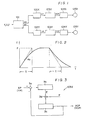
- Figure 1 is a block diagram of a control apparatus to which the first acceleration/deceleration method is applied.
- a coarse interpolator 101 uses the feed velocity F and the travelling distances X, Y along the X and Y axes to compute coarse interpolation data ⁇ X, AY from Eqs.
- the pulse distributors 102X, 102Y which serve as fine interpolators, perform a pulse distributing operation based on the coarse interpolation data AX, AY to generate distributed pulses XP, YP the numbers whereof correspond to ⁇ X, ⁇ Y during one sampling interval.
- the distributed pulses XP, YP are applied to respective acceleration/deceleration circuits 103X, 103Y, disclosed in the specification of U.S.P. 3,838,325.
- each of the acceleration/deceleration circuits 103X, 103Y will have the construction shown in Figure 3, assuming that each performs acceleration and deceleration in exponential fashion, as depicted in Figure 2, during rise time and decay time, respectively.
- numeral 3a denotes a synthesizing circuit for combining the distributed pulses XP (YP) produced by the pulse distributor 102X (102Y), and output pulses XCP (YCP) from the acceleration/deceleration circuit 103X (103Y).
- Numeral 3b denotes a register for storing the pulses produced by the synthesizing circuit 3a.
- Numeral 3c designates an accumulator, and 3d an adder for adding the content E of the register 3b and the content of the accumulator 3c each time a pulse P is produced at a certain pulse rate Fc, with the result of the adding operation being set in the accumulator 3c.
- F the pulse rate of the distributed pulses XP
- Fo the pulse rate of the output pulses XCP
- n represents the number of bits of the accumulator 3c.
- Eq. (3) is the increment of the register 3b per time unit
- Eq. (4) is the number of carry pulses (output pulses XCP) produced by the accumulator 3c per time unit.
- Obtaining the output pulse rate Fo from Eqs. (3) and (4) gives us the following: where k is a constant.
- the output pulse rate Fo is accelerated exponentially at start-up and decelerated exponentially when the movable object is brought to rest.
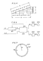
- FIG. 4 is an explanatory view illustrating the manner in which coarse interpolation is performed by the coarse interpolator 101.
- the second acceleration/deceleration method involves performing acceleration and deceleration by applying acceleration and deceleration to the feed velocity input to an interpolator.
- Figure 5 is a block diagram for practicing the second acceleration/deceleration method
- Figure 6 is an explanatory view for describing the manner in which travel is performed.
- an acceleration/deceleration circuit 201 has a construction substantially the same as that shown in Figure 3, the output pulses Fj of the circuit being accelerated and decelerated exponentially during the rise and decay of the feed velocity F, respectively. It should be noted that deceleration is performed automatically when the pulses indicative of the feed velocity F cease arriving.
- the timing at which deceleration starts (the timing at which input of pulses indicating the feed velocity F ceases) is that at which a deceleration distance (already known) commensurate with the feed velocity F becomes equal to a remaining travelling distance Rm.
- An interpolator 202 performs a pulse distributing operation based on travelling distance data X, Y each time the output pulse Fj is generated by the acceleration/deceleration circuit 201, to generate distributed pulses XP, YP for driving servomotors 105X, 105Y through servo circuits 104X, 104Y.
- the output pulse rate (the travelling distance over one sampling interval) of the interpolator 202 is gradually increased and decreased at starting and stopping, respectively, as illustrated in Figure 6.
- the first and second acceleration/deceleration methods are performed as described above.
- the first is advantageous in that the interpolator and acceleration/deceleration circuits are themselves simple in construction. This is bcause it suffices to carry out acceleration/deceleration control entirely independently of interpolation, with acceleration and deceleration merely being performed when interpolation starts and ends, respectively.
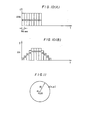
- the first method is disadvantageous in that the path which results from acceleration and deceleration develops an error, as shown in Figure 7, in cases where circular interpolation is performed.
- CCT represents a commanded circle
- ACT denotes the path following acceleration and deceleration.
- the radial error AR in Figure 7 may be approximated by the following: where R represents the radius, T a time constant and F a commanded velocity.
- EP-A-0 025 651 discloses a signal converter circuit having n memory elements for holding the values of an input signal at n different successive timing instants, an adder for adding together the n values, and a divider for dividing the result by n.
- the output of the divider is a smoothed version of the input signal.
- an acceleration/deceleration circuit for raising or lowering a feed velocity of a controlled moveable element, comprising:
- An embodiment of the present invention may provide a novel acceleration/deceleration circuit capable of reducing a path error and of realizing acceleration/deceleration control through a simple arrangement.
- An embodiment of the invention may also provide an acceleration/deceleration circuit capable of performing acceleration or deceleration to achieve a commanded velocity over a prescribed period of time irrespective of the magnitude of the change in velocity.
- An embodiment of the present invention may provide an acceleration/deceleration circuit wherein linear, exponential and any other acceleration/deceleration characteristic can be readily obtained.
- an embodiment of the present invention may provide an acceleration/deceleration circuit wherein an acceleration/deceleration characteristic best suited for the characteristics of a servo loop can be readily set to make possible high-speed positioning and high-speed cutting.
- Figure 1 is a block diagram showing application the first conventional acceleration/deceleration method
- Figure 2 is an explanatory view of exponential-type acceleration/deceleration
- Figure 3 is a block diagram of an exponential-type acceleration/deceleration circuit
- Figure 4 is an explanatory view of the first acceleration/deceleration method
- Figure 5 is a block diagram showing application of the second conventional acceleration/deceleration method
- Figure 6 is an explanatory view of the second acceleration/ deceleration method
- Figure 7 is an explanatory view of path error caused by the first acceleration/ deceleration method
- Figure 8 is an explanatory view of linear-type acceleration/deceleration
- Figure 9 is a block diagram of a first embodiment of the present invention
- Figure 10 is an explanatory view of the first embodiment of the present invention
- Figure 11 is an explanatory view of path error according to the present invention
- Figure 12 is an explanatory view showing a modification of the first embodiment
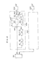
- Figure 13 is a block diagram of a second embodiment of the
- the present invention is directed to minimizing path error following acceleration/deceleration in circular interpolation, and to performing linear acceleration and deceleration, as shown in Figure 8, over time intervals equivalent to a given time constant.
- FIG. 9 is a block diagram of first embodiment of the present invention, in which details are shown solely with regard to X-axis components.
- a coarse interpolator 301 performs the operations of Eqs. (1) and (2) to generate coarse interpolation data ⁇ Xn, ⁇ Yn along the respective axes with every sampling, the data being applied to acceleration/deceleration circuits 302X, 302Y, respectively.
- Each of the acceleration/deceleration circuits 302X, 302Y includes n buffer registers #1, #2,...#(n-1), #n (where n is equivalent to T IT, with ⁇ representing a time constant and T the sampling period), an adder ADD, an accumulator ACC for temporarily storing the results of addition, a register SUM to which the results of addition are transferred, and a divider DIV for dividing the results of addition by n.
- the registers #1 through #n are connected in series. With each sampling, the latest item of interpolation data ⁇ Xn is stored in buffer register #1, the content of each buffer register is transferred to the succeeding buffer register, and the content ⁇ Xo of the final buffer register #n is applied as an input to the adder ADD.
- the n buffer registers #1 through #n constitute an n-stage shift register.
- the adder ADD performs the operation: where St is the content of the register SUM, and plants the results of the addition in the accumulator ACC.
- the content of the accumulator ACC is divided by n by means of the divider DIV, and the result ⁇ X is delivered as the output of the acceleration/deceleration circuit 302X, this being applied to a pulse distributor 303X functioning as a fine interpolator.
- the content of each buffer register (#1 through #n) is shifted to the succeeding buffer register, AXn is stored in the first register #1, and the content St of the accumulator ACC is transferred to the register SUM.
- the shifting operation can be eliminated by providing a pointer indicating which buffer is to produce ⁇ Xo and which is to store AXn.
- a separate accumulator ACC 1 , adder ADD 1 and computing circuit COM can be provided, as illustrated in Figure 12, in consideration of the fact that a remainder may be produced owing to the division by n performed by the divider DIV.
- the computing circuit COM keeps summing a remainder m in each sampling period and the sum is accumulated in the accumulator ACC1.
- 1 is added to the output value ⁇ X of the divider DIV and the resulting value is delivered. Adopting this method makes highly precise acceleration and deceleration possible.
- the acceleration/deceleration circuit subsequently produces the numerical value 10 constantly until the arrival of ⁇ Xn ceases.
- the output ⁇ X of the divider DIV is 8.
- the divider output ⁇ X decreases to 6, 4, 2 and 0, with zero being reached upon passage of the time constant of 40 msec.
- the output value produced by the acceleration/deceleration circuit at a certain time t is obtained by dividing the total of the input values from time t- T to time t by ⁇ , assuming that the time constant T and sampling period T are given by the same units.
- the output value of the acceleration/ deceleration circuit is expressed in dimensions of distance, it may also be taken as velocity since the distance indicative of the output value is travelled in time of the sampling period T. Therefore, the output value of the acceleration/deceleration circuit can be thought of as being the total of the input values from time t- T to time t divided by T .
- the X-axis feed velocity Fx produced by the acceleration/deceleration circuit is obtained from the following equation: where Therefore, if we assume that a position along the X axis following acceleration or deceleration is X', then X' will be given by: If we let then Neglecting terms from the second onward in Eq. (14) gives us: This gives one-twelfth (1/12) the error in comparison with Eq. 6 for exponential-type acceleration/ deceleration.
- Figure 13 is a block diagram of a second embodiment of the present invention, in which details are shown solely with regard to X-axis components.
- Numeral 301 denotes a coarse interpolator which performs the operation of Eqs. (1) and (2) to generate coarse interpolation data (travelling distance components) AXn, AYn along the respective axes whenever sampling is performed, the data being applied to an acceleration/ deceleration circuit.
- Numerals 4a, 4b,...4n denote shift registers each of which stores the travelling distance component ⁇ Xn, with the travelling distance component being shifted from one shift register to the next in response to a shift pulse Ps.
- Numerals 5a through 5n denote multipliers for multiplying the data stored in the shift registers 4a through 4n by respective coefficients K1 through Kn, to which the multipliers have been set. Though the number n of shift registers is equal to T /T, where T is the time constant and T is the sampling period, n need not necessarily be made equal to T / T.
- Numeral 6 designates an adder for adding the results of the multiplication operations performed by the multipliers 5a through 5n.
- Numeral 7 denotes a divider for dividing the sum from the adder 6 by the sum of the coefficients K1 through Kn set in the respective multipliers 5a through 5n.
- Numeral 303X denotes the X-axis pulse distributor for producing distributed pulses the number whereof corresponds to the result ⁇ X of the division performed by the divider 7.
- the shift registers 4a through 4n are connected in series. In response to the shift pulse Ps, data is shifted successively from one shift register to the next.
- the latest travelling distance component, ⁇ Xn produced by the coarse interpolator 301 each time sampling is performed is applied as an input to the shift register 4a. Accordingly, assuming that the contents of the shift registers 4a through 4n are A through N, respectively, the outputs of the multipliers 5a through 5n are A ⁇ K1 through N - Kn, respectively, at sampling time, namely at the instant the travelling distance component ⁇ Xn is produced by the coarse interpolator 301. Consequently, the result XT of the addition performed by the adder 6 is expressed by the following equation:
- the result XD of the division is applied to the pulse distributor 303X, which functions as a fine interpolator, for producing distributed pulses XCP the acceleration and deceleration of which is controlled.
- the accelerating interval and decelerating interval of the acceleration/deceleration circuit are decided by the number of shift registers and the period of the shift pulses Ps.
- the period of the shift pulses Ps is equal to or less than the sampling pulse period.
- the multipliers 5a through 5n, adder 6 and divider constitute computing circuitry, these can be constructed by simple computing means, e.g., a microprocessor. If there is a problem in terms of computation time in connection with the sequential shifting of the shift registers, the shifting operation can be eliminated by adopting a buffer register construction and providing a pointer indicating which buffers are to produce A through N and which is to store ⁇ Xn.
- a separate accumulator, adder and computing circuit can be provided, as described above in connection with Figure 12, in consideration of the fact that a remainder may be produced owing to the division performed by the divider 7. In such case, the remainder is summed every sampling period and the sum is accumulated in the accumulator. When the content of the accumulator exceeds KT, 1 is added to the output value of the divider and the resulting value is delivered. Adopting this method makes highly precise acceleration and deceleration possible.
- the coefficients are all set to the same value. If the values of the coefficients are changed, however, a different acceleration/deceleration coefficient can be obtained.
- an acceleration/deceleration characteristic of the kind shown in Figure 14(C) will be obtained by setting the coefficients K1, K5 to 0.5, K2, K4 to 1.0, and K3 to 2.0.
- Acceleration/deceleration characteristics can be set at will in accordance with servo circuit and servomotor characteristics, and can be readily attained merely by setting the coefficients.
- acceleration or deceleration can be carried out linearly within a certain period of time, irrespective of the size of a change in velocity, in order to achieve a commanded velocity, and a path error along a circular arc can be made smaller than that obtained in the prior art.
- acceleration/deceleration control according to the invention can be carried out entirely independently of interpolation, the acceleration/deceleration circuitry is simple in construction.
- any acceleration/deceleration characteristic can be obtained. This makes it possible to set a characteristic best suited to the servo loop characteristic, and to carry out high-speed positioning and high-speed cutting.
- the setting of an acceleration/ deceleration characteristic can be achieved very easily merely by altering a multiplication coefficient. This is accomplished without an increase in the complexity of the arrangement which, as a result, is simple in construction.
- the acceleration/deceleration circuit of the present invention is well-suited for driving, e.g., a movable element of a machine tool or a hand of a robot.
Landscapes
- Engineering & Computer Science (AREA)
- Human Computer Interaction (AREA)
- Manufacturing & Machinery (AREA)
- Physics & Mathematics (AREA)
- General Physics & Mathematics (AREA)
- Automation & Control Theory (AREA)
- Computing Systems (AREA)
- Theoretical Computer Science (AREA)
- Numerical Control (AREA)
- Automatic Control Of Machine Tools (AREA)
Abstract
Claims (4)
Applications Claiming Priority (2)
| Application Number | Priority Date | Filing Date | Title |
|---|---|---|---|
| JP172863/82 | 1982-10-01 | ||
| JP57172863A JPS5962909A (ja) | 1982-10-01 | 1982-10-01 | 加減速装置 |
Publications (3)
| Publication Number | Publication Date |
|---|---|
| EP0120970A1 EP0120970A1 (fr) | 1984-10-10 |
| EP0120970A4 EP0120970A4 (fr) | 1986-12-01 |
| EP0120970B1 true EP0120970B1 (fr) | 1990-12-05 |
Family
ID=15949688
Family Applications (1)
| Application Number | Title | Priority Date | Filing Date |
|---|---|---|---|
| EP83903111A Expired EP0120970B1 (fr) | 1982-10-01 | 1983-09-30 | Circuit d'acceleration et de deceleration |
Country Status (5)
| Country | Link |
|---|---|
| US (1) | US4554497A (fr) |
| EP (1) | EP0120970B1 (fr) |
| JP (1) | JPS5962909A (fr) |
| DE (1) | DE3382051D1 (fr) |
| WO (1) | WO1984001444A1 (fr) |
Families Citing this family (41)
| Publication number | Priority date | Publication date | Assignee | Title |
|---|---|---|---|---|
| JPS59161252A (ja) * | 1983-03-04 | 1984-09-12 | Fanuc Ltd | 倣い制御装置 |
| JPS6118009A (ja) * | 1984-07-04 | 1986-01-25 | Fanuc Ltd | 加減速制御方式 |
| JPS61107403A (ja) * | 1984-10-31 | 1986-05-26 | Amada Co Ltd | 移動制御方法 |
| JPH0642166B2 (ja) * | 1985-04-26 | 1994-06-01 | 株式会社サンエス商工 | サ−ボ制御方法 |
| US4775945A (en) * | 1985-12-11 | 1988-10-04 | International Business Machines Corporation | Print head motor control system with automatic drive parameter calculations |
| JPH0646367B2 (ja) * | 1986-09-29 | 1994-06-15 | 株式会社エスジ− | 位置決め制御における進み角補償方式 |
| JPS63123605A (ja) * | 1986-11-12 | 1988-05-27 | Fanuc Ltd | タツピング加工制御装置 |
| US4774445A (en) * | 1986-11-20 | 1988-09-27 | Unimation, Inc. | Multiaxis robot control having capability for executing timed moves |
| JPH0711764B2 (ja) * | 1986-12-02 | 1995-02-08 | 東芝機械株式会社 | 加減速制御装置 |
| JPS63167906A (ja) * | 1986-12-29 | 1988-07-12 | Hitachi Seiko Ltd | サ−ボ制御装置 |
| JPS63273107A (ja) * | 1987-04-30 | 1988-11-10 | Fanuc Ltd | ロボット制御装置 |
| JPS63273108A (ja) * | 1987-04-30 | 1988-11-10 | Fanuc Ltd | 速度制御装置 |
| JPH0732979B2 (ja) * | 1987-06-17 | 1995-04-12 | ファナック株式会社 | 加減速制御装置 |
| JP2707087B2 (ja) * | 1987-09-09 | 1998-01-28 | ファナック株式会社 | ロボット制御装置 |
| JPH01113809A (ja) * | 1987-10-28 | 1989-05-02 | Hitachi Seiko Ltd | サーボ制御装置 |
| JPH01164280A (ja) * | 1987-12-21 | 1989-06-28 | Fanuc Ltd | 加減速制御方式 |
| JP2716446B2 (ja) * | 1988-02-02 | 1998-02-18 | 日立精工株式会社 | サーボ制御装置 |
| JP2581585B2 (ja) * | 1988-03-18 | 1997-02-12 | 三菱電機株式会社 | 加減速制御装置 |
| DE58902651D1 (de) * | 1988-05-03 | 1992-12-17 | Siemens Ag | Verfahren zum steuern der bewegung eines maschinenelementes. |
| JP2808119B2 (ja) * | 1988-07-28 | 1998-10-08 | ファナック株式会社 | 加減速制御方式 |
| KR900017735A (ko) * | 1989-05-19 | 1990-12-19 | 강진구 | 이송물의 직선 이송방법 |
| EP0419706B1 (fr) * | 1989-09-27 | 1995-01-25 | Siemens Aktiengesellschaft | Méthode de commande numérique de position ou de trajectoire |
| JPH03281083A (ja) * | 1990-03-29 | 1991-12-11 | Fanuc Ltd | Cncレーザ加工機の姿勢制御方式 |
| JP2897333B2 (ja) * | 1990-04-11 | 1999-05-31 | ブラザー工業株式会社 | サーボ制御装置 |
| JPH0430203A (ja) * | 1990-05-25 | 1992-02-03 | Fanuc Ltd | ロボットの加減速時定数制御方法 |
| US5311110A (en) * | 1990-11-08 | 1994-05-10 | Fanuc Ltd. | Feedforward control method for servomotors |
| KR940002206B1 (ko) * | 1991-01-26 | 1994-03-19 | 삼성전자 주식회사 | 컨벌루션(Convolution)을 이용한 로보트의 궤적발생방법 |
| US5396160A (en) * | 1991-03-11 | 1995-03-07 | General Motors Corporation | Method of real-time machine path planning from a math model |
| JP3083870B2 (ja) * | 1991-05-10 | 2000-09-04 | ファナック株式会社 | 数値制御装置 |
| JPH06180606A (ja) * | 1992-12-11 | 1994-06-28 | Mitsubishi Electric Corp | 駆動対象物の制御装置 |
| JP3046177B2 (ja) * | 1993-05-10 | 2000-05-29 | オークマ株式会社 | 加減速制御装置 |
| US5434489A (en) * | 1993-07-30 | 1995-07-18 | Fanuc Robotics North America, Inc. | Method and system for path planning in cartesian space |
| US5602968A (en) * | 1994-05-02 | 1997-02-11 | The United States Of America As Represented By The Administrator Of The National Aeronautics And Space Administration | Task space angular velocity blending for real-time trajectory generation |
| US5740327A (en) * | 1994-12-27 | 1998-04-14 | Nec Corporation | Method of and apparatus for robot tip trajectory control |
| JP3000889B2 (ja) * | 1995-06-13 | 2000-01-17 | ダイキン工業株式会社 | ロボットの軌跡制御方法 |
| JP3235535B2 (ja) * | 1997-09-26 | 2001-12-04 | 松下電器産業株式会社 | ロボット制御装置とその制御方法 |
| JPH11149306A (ja) * | 1997-11-14 | 1999-06-02 | Fanuc Ltd | 加工機の制御装置 |
| JP3673383B2 (ja) * | 1997-12-12 | 2005-07-20 | ファナック株式会社 | ロボットの制御装置 |
| US5917301A (en) * | 1998-02-27 | 1999-06-29 | Samsung Aerospace Industries, Ltd. | Method for generating a motion profile of a motor |
| CN103365235A (zh) * | 2012-04-05 | 2013-10-23 | 优配尼斯有限公司 | 电动机控制分析器 |
| JP6133825B2 (ja) | 2014-08-28 | 2017-05-24 | ファナック株式会社 | 反転時の最適な加速度を算出する数値制御装置 |
Family Cites Families (6)
| Publication number | Priority date | Publication date | Assignee | Title |
|---|---|---|---|---|
| US3838325A (en) * | 1973-08-30 | 1974-09-24 | K Kobayashi | Motor speed acceleration-deceleration control circuit |
| JPS5574605A (en) * | 1978-11-29 | 1980-06-05 | Hitachi Ltd | Operation control system for industrial robbot or the like |
| JPS5633703A (en) * | 1979-08-25 | 1981-04-04 | Fanuc Ltd | Signal converting circuit |
| JPS6023939B2 (ja) * | 1979-09-28 | 1985-06-10 | ファナック株式会社 | 倣い制御方式 |
| JPS57189217A (en) * | 1981-05-18 | 1982-11-20 | Nec Corp | Positioning controller |
| US4486693A (en) * | 1982-07-06 | 1984-12-04 | Contitronix, Inc. | Motor velocity control |
-
1982
- 1982-10-01 JP JP57172863A patent/JPS5962909A/ja active Granted
-
1983
- 1983-09-30 WO PCT/JP1983/000326 patent/WO1984001444A1/fr not_active Ceased
- 1983-09-30 DE DE8383903111T patent/DE3382051D1/de not_active Expired - Lifetime
- 1983-09-30 EP EP83903111A patent/EP0120970B1/fr not_active Expired
- 1983-09-30 US US06/610,983 patent/US4554497A/en not_active Expired - Lifetime
Also Published As
| Publication number | Publication date |
|---|---|
| JPH045202B2 (fr) | 1992-01-30 |
| EP0120970A4 (fr) | 1986-12-01 |
| JPS5962909A (ja) | 1984-04-10 |
| EP0120970A1 (fr) | 1984-10-10 |
| WO1984001444A1 (fr) | 1984-04-12 |
| DE3382051D1 (de) | 1991-01-17 |
| US4554497A (en) | 1985-11-19 |
Similar Documents
| Publication | Publication Date | Title |
|---|---|---|
| EP0120970B1 (fr) | Circuit d'acceleration et de deceleration | |
| US4706003A (en) | Acceleration and deceleration control system | |
| EP0077178B1 (fr) | Système de régulation de moteur pour fonctionnement en synchronisme | |
| EP0137857B1 (fr) | Procede de commande numerique | |
| Suh et al. | Theory and design of CNC systems | |
| EP0103351B1 (fr) | Méthode et dispositif de commande numérique | |
| US5057756A (en) | Acceleration/deceleration control apparatus for servo control | |
| JPS61157909A (ja) | ロボツトの経路誤差補正方式 | |
| US5004968A (en) | Method for acceleration and deceleration control of servomotors | |
| EP0406784B1 (fr) | Equipement pour interpolation polynomiale pour commandes numériques de machines, specialement pour une machine à meuler pour la fabrication de matrices, et machine ainsi equipée | |
| KR970022624A (ko) | 시간 이산 샘플링 시스템에서 클록 동기 이동제어 방법 및 장치 | |
| US5510996A (en) | Method for determining auxiliary position-control parameters | |
| US4164693A (en) | Method and system for producing linear contouring movement | |
| JP3219195B2 (ja) | 数値制御における送り速度制御方法 | |
| JPS5990107A (ja) | 加減速回路 | |
| JPS61245209A (ja) | 加減速制御方式 | |
| US4020331A (en) | Feed rate control system for numerical control machine tool | |
| US3731175A (en) | Servo system for velocity and position control | |
| JP3023648B2 (ja) | 位置制御装置 | |
| US4584509A (en) | Method of discriminating present position region of a machine | |
| JPS60209812A (ja) | 加減速制御方式 | |
| JP2800124B2 (ja) | 数値制御工作機械の制御方法及びそのための制御装置 | |
| KR100427522B1 (ko) | 연속이동경로 생성방법 | |
| US5043645A (en) | NC statement preparing system | |
| JPS61157910A (ja) | 加減速制御方式 |
Legal Events
| Date | Code | Title | Description |
|---|---|---|---|
| PUAI | Public reference made under article 153(3) epc to a published international application that has entered the european phase |
Free format text: ORIGINAL CODE: 0009012 |
|
| 17P | Request for examination filed |
Effective date: 19840604 |
|
| AK | Designated contracting states |
Kind code of ref document: A1 Designated state(s): DE FR GB Designated state(s): DE FR GB |
|
| A4 | Supplementary search report drawn up and despatched |
Effective date: 19861201 |
|
| 17Q | First examination report despatched |
Effective date: 19880921 |
|
| GRAA | (expected) grant |
Free format text: ORIGINAL CODE: 0009210 |
|
| AK | Designated contracting states |
Kind code of ref document: B1 Designated state(s): DE FR GB |
|
| ET | Fr: translation filed | ||
| REF | Corresponds to: |
Ref document number: 3382051 Country of ref document: DE Date of ref document: 19910117 |
|
| PLBE | No opposition filed within time limit |
Free format text: ORIGINAL CODE: 0009261 |
|
| STAA | Information on the status of an ep patent application or granted ep patent |
Free format text: STATUS: NO OPPOSITION FILED WITHIN TIME LIMIT |
|
| 26N | No opposition filed | ||
| PGFP | Annual fee paid to national office [announced via postgrant information from national office to epo] |
Ref country code: FR Payment date: 19940909 Year of fee payment: 12 |
|
| PG25 | Lapsed in a contracting state [announced via postgrant information from national office to epo] |
Ref country code: FR Effective date: 19960531 |
|
| REG | Reference to a national code |
Ref country code: FR Ref legal event code: ST |
|
| REG | Reference to a national code |
Ref country code: GB Ref legal event code: IF02 |
|
| PGFP | Annual fee paid to national office [announced via postgrant information from national office to epo] |
Ref country code: GB Payment date: 20020925 Year of fee payment: 20 |
|
| PGFP | Annual fee paid to national office [announced via postgrant information from national office to epo] |
Ref country code: DE Payment date: 20021011 Year of fee payment: 20 |
|
| PG25 | Lapsed in a contracting state [announced via postgrant information from national office to epo] |
Ref country code: GB Free format text: LAPSE BECAUSE OF EXPIRATION OF PROTECTION Effective date: 20030929 |
|
| REG | Reference to a national code |
Ref country code: GB Ref legal event code: PE20 |