EP0103351B1 - Méthode et dispositif de commande numérique - Google Patents
Méthode et dispositif de commande numérique Download PDFInfo
- Publication number
- EP0103351B1 EP0103351B1 EP83303122A EP83303122A EP0103351B1 EP 0103351 B1 EP0103351 B1 EP 0103351B1 EP 83303122 A EP83303122 A EP 83303122A EP 83303122 A EP83303122 A EP 83303122A EP 0103351 B1 EP0103351 B1 EP 0103351B1
- Authority
- EP
- European Patent Office
- Prior art keywords
- speed
- tool
- numerical control
- control
- command data
- Prior art date
- Legal status (The legal status is an assumption and is not a legal conclusion. Google has not performed a legal analysis and makes no representation as to the accuracy of the status listed.)
- Expired
Links
Images


Classifications
-
- G—PHYSICS
- G05—CONTROLLING; REGULATING
- G05B—CONTROL OR REGULATING SYSTEMS IN GENERAL; FUNCTIONAL ELEMENTS OF SUCH SYSTEMS; MONITORING OR TESTING ARRANGEMENTS FOR SUCH SYSTEMS OR ELEMENTS
- G05B19/00—Program-control systems
- G05B19/02—Program-control systems electric
- G05B19/18—Numerical control [NC], i.e. automatically operating machines, in particular machine tools, e.g. in a manufacturing environment, so as to execute positioning, movement or co-ordinated operations by means of program data in numerical form
- G05B19/408—Numerical control [NC], i.e. automatically operating machines, in particular machine tools, e.g. in a manufacturing environment, so as to execute positioning, movement or co-ordinated operations by means of program data in numerical form characterised by data handling or data format, e.g. reading, buffering or conversion of data
-
- G—PHYSICS
- G05—CONTROLLING; REGULATING
- G05B—CONTROL OR REGULATING SYSTEMS IN GENERAL; FUNCTIONAL ELEMENTS OF SUCH SYSTEMS; MONITORING OR TESTING ARRANGEMENTS FOR SUCH SYSTEMS OR ELEMENTS
- G05B19/00—Program-control systems
- G05B19/02—Program-control systems electric
- G05B19/18—Numerical control [NC], i.e. automatically operating machines, in particular machine tools, e.g. in a manufacturing environment, so as to execute positioning, movement or co-ordinated operations by means of program data in numerical form
- G05B19/416—Numerical control [NC], i.e. automatically operating machines, in particular machine tools, e.g. in a manufacturing environment, so as to execute positioning, movement or co-ordinated operations by means of program data in numerical form characterised by control of velocity, acceleration or deceleration
-
- G—PHYSICS
- G05—CONTROLLING; REGULATING
- G05B—CONTROL OR REGULATING SYSTEMS IN GENERAL; FUNCTIONAL ELEMENTS OF SUCH SYSTEMS; MONITORING OR TESTING ARRANGEMENTS FOR SUCH SYSTEMS OR ELEMENTS
- G05B2219/00—Program-control systems
- G05B2219/30—Nc systems
- G05B2219/35—Nc in input of data, input till input file format
- G05B2219/35356—Data handling
-
- G—PHYSICS
- G05—CONTROLLING; REGULATING
- G05B—CONTROL OR REGULATING SYSTEMS IN GENERAL; FUNCTIONAL ELEMENTS OF SUCH SYSTEMS; MONITORING OR TESTING ARRANGEMENTS FOR SUCH SYSTEMS OR ELEMENTS
- G05B2219/00—Program-control systems
- G05B2219/30—Nc systems
- G05B2219/43—Speed, acceleration, deceleration control ADC
- G05B2219/43009—Acceleration deceleration for each block of data, segment
-
- G—PHYSICS
- G05—CONTROLLING; REGULATING
- G05B—CONTROL OR REGULATING SYSTEMS IN GENERAL; FUNCTIONAL ELEMENTS OF SUCH SYSTEMS; MONITORING OR TESTING ARRANGEMENTS FOR SUCH SYSTEMS OR ELEMENTS
- G05B2219/00—Program-control systems
- G05B2219/30—Nc systems
- G05B2219/49—Nc machine tool, till multiple
- G05B2219/49164—Corner, making corner
Definitions
- This invention relates to a numerical control method and apparatus suitable for application to the cutting of corner portions by means of a gas or plasma cutting machine.
- a so-called data prereading technique is used as a method of reading data in a numerical control apparatus.
- the reasons are as follows.
- a succeeding block of NC data is read each time machining or movement based on the preceding block ends.
- This is followed by a format check, decoding, calculation of an amount of movement (incremental values), and by other preprocessing, after which machining or movement is controlled based upon said succeeding block.
- machining efficiency declines because processing cannot keep up with the action of the machine tool owing to preprocessing time and the response of a motor for driving a table or the like. It is for this reason that the abovementioned data prereading technique has come into use.
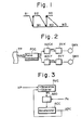
- NCdata in the succeeding block B2 is preread and preprocessing based on the succeeding block B2 is performed in advance concurrently with NC machining control W1 based on the current block B1. Then, simultaneously with the completion of NC machining control specified by the current block B1, NC machining control W2 is performed on the basis of the NC data in the succeeding block B2. Therefore, according to the data prereading method, movement based on the NC data in the succeeding block can be executed immediately without waiting for the completion of preprocessing following movement based on the NC data in the current block. The result is a more efficient machining operation; see e.g. EP-A-68 765.
- the servo loop of a numerical control system is provided with an acceleration/deceleration circuit connected to the output of a pulse distributor in order to prevent a mechanical system from sustaining a shock at the beginning and end of movement.
- the circuit serves to accelerate and then decelerate the pulse rate of a pulse train generated by the pu Ise distributor as the resu It of a pulse distribution computation.
- Fig. 2 is a block diagram of a servo loop of the kind described, adapted for the control of two axes, namely the X and Y axes.
- a pulse distributor PDC receives, as inputs thereto, data Xc, Yc indicative of commanded amounts of movement along the X and Y axes, as well as a commanded feed speed Fc, these being read in from an NC tape TP. Using these inputs, the pulse distributor PDC performs a known pulse distribution computation to generate distributed pulses Xp, Yp that are applied to acceleration/deceleration circuits ADCX, ADCY, respectively.
- the acceleration/deceleration circuits ADCX, ADCYfunction to accelerate the pulse rate of the distributed pulses up to the commanded speed Fc when the pulses begin to arrive, and to decelerate the pulse rate when the arrival of distributed pulses is interrupted.
- Pulses XPC, YPC resulting from the acceleration and deceleration operation of the circuits ADCX, ADCY are applied to respective servo circuits SVX, SVY to drive servomotors SMX, SMY for drive along the X and Y axes, respectively.
- FIG. 3 A block diagram of an acceleration/deceleration circuit is illustrated in Fig. 3. It should be noted that the circuit controls acceleration and deceleration exponentially or linearly.
- RVC represents a reversible counter for counting up the distributed pulses Xp and for counting down the output pulses XPC.
- ACC denotes an n-bit accumulator, and ADD an adder for adding the contents PE of the reversible counter RVC to the contents of the accumulator ACC whenever a pulse Pa is generated at a constant frequency Fa.
- the pulses XPC emerge from the accumulator at a pulse rate Fc' given by the following:
- Fc' increases exponentially during rise time, and decreases exponentially during decay time.
- the acceleration/deceleration circuit can also be constructured to control acceleration and deceleration linearly, in which case Fc' will be given by: and the pulse rate will increase linearly during rise time and decrease linearly during decay time.
- blocks B1, B2 preceding and following a corner CP intersect at right angles at the corner CP.
- the preceding block B1 is parallel to the X axis
- the following block B2 is parallel to the Y axis.
- the cutting speed along the X-axis decreases exponentially from a commanded speed Vi x in the vicinity of the corner, as shown in Fig. 4(B).
- a pulse distribution computation based on the command data in the following block B2 starts from a time to, which isthe instant atwhich deceleration begins in the preceding block B1 (namely the instant at which the pulse distribution computation ends,in block B1), as shown in Fig.
- a tool path is dependent upon the following:
- the difference between a tool path and a commanded path depends upon these parameters.
- the difference between the tool path and commanded path results in a machining error which is required to be held within allowable limits.
- programming is performed during the creation of an NC tape to set the feed speeds so that the error will fall within the allowable limits, or a dwell commande (G04) is inserted between items of command data corresponding to the blocks on either side of a corner, whereby interpolation for a succeeding block starts upon the completion of deceleration in the preceding block, thereby to eliminate rounding of the corner portion.
- the former method involves complicated programming
- the latter method in which pulse distribution in a succeeding block starts at the end of deceleration, requires a considerable length of time to pass the corner portion.
- a cutting machine such as a gas or plasma cutter
- the corner portion cannot be cut sharply and may instead be cut too widely.
- an object of the present invention is to provide a numerical control method and an apparatus therefor capable of improving the accuracy at which a corner portion is cut, particularly when applied to a gas or plasma cutting machine.
- Another object of the present invention is to provide a numerical control method and an apparatus therefore capable of shortening the time required for cutting a corner portion, and of cutting a corner portion to a sharp angle.
- the present invention is directed to a numerical control method and apparatus wherein first and second tool control blocks providing for movements of the tool precede and follow a corner on a tool path, with the blocks being controlled sequentially.
- a pulse distribution computation based on NC command data in the second block is not executed at the instant that a pulse distribution computation based on NC command data in the first block ends. Rather, a pulse distribution computation based on the NC command data in the second block is performed starting at the instant that a feed speed based on the NC command data in the first block attains a prescribed speed by being decelerated.
- the arrangement is such that interpolation in a succeeding block of data starts after the feed speed in the preceding block is decelerated until a prescribed speed is attained.
- FIG. 5 (A) shows the shape of a corner portion on a tool path
- (B), (C) depict feed speed along the X and Y axes, respectively.
- the solid lines correspond to the prior-art feed speeds, and the dashed line to the feed speeds according to the present invention.
- blocks B1, B2 preceding and following a corner CP intersect at right angles at the corner CP.
- the preceding block B1 is parallel to the X axis
- the following block B2 is parallel to the Y axis.
- a pulse distribution computation based on command data in a succeeding block is not executed at the instant to, which is the time at which a pulse distribution computation based on the command data in the preceding block ends. Rather, a pulse distribution computation based on the command data in the succeeding block is performed starting from time t" which is the instant at which the feed speed based on the command data in the preceding block attains a prescribed speed Vs by being decelerated.
- time t which is the instant at which the feed speed based on the command data in the preceding block attains a prescribed speed Vs by being decelerated.
- Fig. 6 illustrates another embodiment of the present invention.
- (A) shows the shape of a corner portion on a tool path
- (B), (C) depict feed speed along the X and Y axes, respectively.
- the solid lines correspond to the prior-art feed speeds, and the dashed line to the feed speeds according to the present invention.
- acceleration and deceleration are performed linearly at the corner portion of the tool path.
- the pulse distribution computation based on the command data in the succeeding block is performed starting from time t 1 , which is the instant at which the feed speed based on the command data in the preceding block attains a prescribed speed Vs by being decelerated in linear fashion, rather than exponentially.
- the corner portion can be cut with even greater accuracy in comparison with the exponential acceleration and deceleration practiced in Fig. 5.
- the prescribed speed Vs can be selected in accordance with the feed speed of the tool, the angle of the corner portion and the type of motor used.
- Numeral 101 denotes a paper tape in which numerical control (NC) data are punched.
- Numeral 102 denotes a control unit which causes a tape reader (not shown) to read in the NC command data from the paper tape 101, and which decodes the read NC data, delivering, e.g., M, S and T function commands to the machine side through a power magnetics unit (not shown), and move commands to pulse distributors 103X, 103Y.
- the control unit 102 is further adapted to store the NC data in a buffer register, not shown.
- the pulse distributors 103X, 103Y execute well-known pulse distribution computations on the basis of move commands Xc, Yc from the control unit 102, and generate distributed pulses XP, YP, respectively, at a frequency corresponding to respective command speeds Fc x , Fey received from the control unit 102.
- Numerals 104X, 104Y designate respective acceleration/deceleration circuits for generating pulse trains XPC, YPC by accelerating the pulse rates of the distributed pulse trains XP, YP exponentially or linearly at the occurrence of these pulse trains, and for decelerating these pulse rates exponentially or linearly at the end of the distributed pulse trains.
- Numerals 105X, 105Y denote DC motors, respectively, for transporting a table or tool, not shown.
- Pulse coders 106X, 106Y generate one feedback pulse FPX, FPY, respectively, each time the corresponding DC motor rotates by a predetermined amount.
- the pulse trains XPC, YPC from the circuits 104X, 104Y are applied to respective error calculating and storing units 107X, 107Y each of which is constituted by, for example, a reversible counter.
- the units 107X, 107Y compute the differences Ex, Ey between the number of pulses XPY, YP c received from the acceleration/deceleration circuits 104X, 104Y, and the number of feedback pulses FPX, FPY, and are further adapted to store Ex and Ey, respectively.
- error calculating and storing units may be constructed, as shown in the figure, of an arithmetic circuit 107a for calculating the difference Ex or Ey between the numbers of pulses XPC, FPX, or YPC, FPY, input thereto, and an error register 107b for storing the error Ex or Ey.
- the error calculating and storing units 107X, 107Y operate in such a manner that each time the input pulses XPC, YPC are generated, these are counted up by means of the arithmetic circuits 107a, while each time the feedback pulses FPX, FPY are generated, the contents of the units 107X, 107Y are counted down, and that the differences Ex, Ey between the number of input pulses and the number of feedback pulses are stored in the error registers 107b.
- Numerals 108X, 108Y denote DA (digital-to- analog) converters for generating analog voltages proportional to the contents of the error registers 107b. These analog voltages are applied to speed control circuits 109X, 109Y.
- Numerals 11 OX, 110Y designate counters for counting the pulses XPC, YPC generated by the acceleration/deceleration circuits 104A, 104Y, respectively. The values Xs, Ys counted by the counters 110X, 110Y are applied to a read circuit 111 which reads the counted values Xs, Ys at discrete times and then clears the counters 110X, 110Y.
- the output of the read circuit 111 is connected to an arithmetic circuit 112 which computes actual speed Va by performing the operation
- a comparator 113 compares the actual speed Va with a preset speed Vs (Fig. 6), and delivers a pulse distribution start signal PDS to the pulse distributors 103X, 103Y when the actual speed Va falls below the preset speed Vs.
- the control unit 102 When an item of NC data read in from the NC tape 101 is a cutting command [the NC data in block B1 of Fig. 5(A)], the control unit 102 responds by computing an incremental value that is applied, together with a speed command, to the pulse distributor 103X.
- the control unit 102 also causes the tape reader (not shown) to read in the NC data in the succeeding block B2.
- the pulse distributor 103X produces the distributed pulses XP by performing a pulse distribution computation based on the received incremental value and speed command Fc x .
- the acceleration/deceleration circuit 104X accelerates and decelerates the pulse rate thereof and applies the resulting pulse train XPC to the error calculating and storing circuit 107X.
- the content of the error register 107b becomes non-zero, so that the DA converter 108X provides a voltage and the motor 105X is driven by the speed control circuit 109X so as to move a table.
- the feedback pulse FPX is generated by the pulse coder 106X and is applied to the error calculating and storing unit 107X, with the error register 107b storing the difference Es between the number of pulses XPC and the number of feedback pulses FPX.
- the table is servo-controlled in such a manner that the difference Ex approaches zero, with the table being moved to a target position or transported along a commanded path at the speed Fc X .
- the pulse distribution operation performed by the pulse distributor 103X ceases and the traveling speed of the table along the X axis declines.
- the counters 11 OX, 110Y are counting the numbers of pulses XPC, YPC generated at discrete times by the acceleration/deceleration circuits 104X, 104Y.
- the numbers of counted pulses namely Xs, Yx, which are equivalent to the speeds along the X and Y axes, respectively, are read by the read circuit 112 at discrete times and are applied to the arithmetic circuit 112, which performs the operation
- the magnitude of Va is approximately equal to the actual speed, and is compared with the prescribed speed Vs by means of the comparator 112.
- the prescribed speed Vs can be set appropriately by taking into consideration the feed speed of the tool, the angle of the corner portion, and the type of motor used.
- means 114 is provided for setting Vs in response to a suitable value entered from a manual data input unit (MDI) 115.
- MDI manual data input unit
- the comparator 113 When the result of the comparison operation performed by the comparator 113 is Vs?Va, the comparator applies the pulse distribution start signal PDS to the pulse distributors 103X, 103Y so that a pulse distribution computation based on the next block of NC data will be performed.
- the control unit 102 controls the tape reader, causing it to read in NC data from the paper tape 101 one block after another. The foregoing operations are then repeated in similar fashion.
Landscapes
- Engineering & Computer Science (AREA)
- Human Computer Interaction (AREA)
- Manufacturing & Machinery (AREA)
- Physics & Mathematics (AREA)
- General Physics & Mathematics (AREA)
- Automation & Control Theory (AREA)
- Numerical Control (AREA)
Claims (6)
Applications Claiming Priority (2)
| Application Number | Priority Date | Filing Date | Title |
|---|---|---|---|
| JP57093500A JPS58211211A (ja) | 1982-06-01 | 1982-06-01 | 数値制御方式 |
| JP93500/82 | 1982-06-01 |
Publications (3)
| Publication Number | Publication Date |
|---|---|
| EP0103351A2 EP0103351A2 (fr) | 1984-03-21 |
| EP0103351A3 EP0103351A3 (en) | 1985-09-18 |
| EP0103351B1 true EP0103351B1 (fr) | 1989-08-30 |
Family
ID=14084064
Family Applications (1)
| Application Number | Title | Priority Date | Filing Date |
|---|---|---|---|
| EP83303122A Expired EP0103351B1 (fr) | 1982-06-01 | 1983-05-31 | Méthode et dispositif de commande numérique |
Country Status (4)
| Country | Link |
|---|---|
| US (1) | US4600985A (fr) |
| EP (1) | EP0103351B1 (fr) |
| JP (1) | JPS58211211A (fr) |
| DE (1) | DE3380500D1 (fr) |
Families Citing this family (37)
| Publication number | Priority date | Publication date | Assignee | Title |
|---|---|---|---|---|
| US4815007A (en) * | 1984-12-20 | 1989-03-21 | Seiko Epson Corporation | Apparatus for controlling a robot |
| JPS61157909A (ja) * | 1984-12-29 | 1986-07-17 | Fanuc Ltd | ロボツトの経路誤差補正方式 |
| JPS61161517A (ja) * | 1985-01-09 | 1986-07-22 | Toko Inc | 補間装置 |
| JPS61241039A (ja) * | 1985-04-16 | 1986-10-27 | Nippei Toyama Corp | クランプ確認装置 |
| JPS61269707A (ja) * | 1985-05-24 | 1986-11-29 | Hitachi Seiki Co Ltd | Nc工作機械の加工寸法補正制御装置 |
| JPS6225302A (ja) * | 1985-07-25 | 1987-02-03 | Fanuc Ltd | 数値制御装置 |
| JPS62130411A (ja) * | 1985-11-30 | 1987-06-12 | Fanuc Ltd | 数値制御方法 |
| JPS62130412A (ja) * | 1985-12-03 | 1987-06-12 | Fanuc Ltd | 数値制御方法 |
| JPS63123605A (ja) * | 1986-11-12 | 1988-05-27 | Fanuc Ltd | タツピング加工制御装置 |
| JPS63181005A (ja) * | 1987-01-23 | 1988-07-26 | Fanuc Ltd | 数値制御装置の並列処理方式 |
| JPS63235084A (ja) * | 1987-03-20 | 1988-09-30 | Fanuc Ltd | レ−ザ発振制御装置 |
| JPS63254502A (ja) * | 1987-04-10 | 1988-10-21 | Fanuc Ltd | ロボツト制御装置 |
| JPH0732979B2 (ja) * | 1987-06-17 | 1995-04-12 | ファナック株式会社 | 加減速制御装置 |
| JPH01164280A (ja) * | 1987-12-21 | 1989-06-28 | Fanuc Ltd | 加減速制御方式 |
| JP2735126B2 (ja) * | 1988-12-27 | 1998-04-02 | キヤノン株式会社 | ロボットの制御方法及びその制御装置 |
| KR910005243B1 (ko) * | 1988-12-30 | 1991-07-24 | 삼성전자 주식회사 | 지수함수적 가감속에 의한 서보모터의 위치제어장치 및 방법 |
| KR900017735A (ko) * | 1989-05-19 | 1990-12-19 | 강진구 | 이송물의 직선 이송방법 |
| JPH04111006A (ja) * | 1990-08-30 | 1992-04-13 | Kobe Steel Ltd | ロボットの経路補間方法 |
| DE59008488D1 (de) * | 1990-09-27 | 1995-03-23 | Siemens Ag | Vefahren zum Bearbeiten von Werkstücken mit einer numerisch gesteuerten Maschine. |
| DE69229309T2 (de) * | 1991-08-30 | 1999-11-18 | Makino Milling Machine Co. Ltd., Tokio/Tokyo | Verfahren und Vorrichtung zur Überwachung des Vorschubes in numerisch gesteuerten Systemen |
| US5444636A (en) * | 1991-08-30 | 1995-08-22 | Makino Milling Machine Co., Ltd. | Method and apparatus for controlling feed rate at arcuate portions |
| JP3395278B2 (ja) * | 1993-09-16 | 2003-04-07 | ソニー株式会社 | 数値制御方法と数値制御装置 |
| US5508596A (en) * | 1993-10-07 | 1996-04-16 | Omax Corporation | Motion control with precomputation |
| JP3625901B2 (ja) | 1995-06-30 | 2005-03-02 | 三菱電機株式会社 | サーボ制御システムの自動適正化方法および装置 |
| US6317646B1 (en) * | 1997-03-19 | 2001-11-13 | Fadal Machining Centers, Inc. | CNC machine having interactive control of corner tolerance that is programmed to vary with the corner angle |
| JPH11143519A (ja) * | 1997-11-07 | 1999-05-28 | Fanuc Ltd | 数値制御における加減速制御方法および数値制御装置 |
| WO2001054469A1 (fr) * | 2000-01-17 | 2001-07-26 | Matsushita Electric Industrial Co., Ltd. | Procede et dispositif de commande de positionnement et dispositif de montage de pieces electroniques mettant en oeuvre ledit dispositif de commande |
| KR101220121B1 (ko) * | 2006-06-30 | 2013-01-11 | 스타 마이크로닉스 컴퍼니 리미티드 | 이동체의 이동 제어 장치, 이동체의 이동 제어 방법 및공작 기계의 이동 제어 장치 |
| US7979158B2 (en) * | 2007-07-31 | 2011-07-12 | Rockwell Automation Technologies, Inc. | Blending algorithm for trajectory planning |
| US8904912B2 (en) | 2012-08-16 | 2014-12-09 | Omax Corporation | Control valves for waterjet systems and related devices, systems, and methods |
| JP6585558B2 (ja) * | 2016-07-19 | 2019-10-02 | ファナック株式会社 | 稼働管理システム及び計測システム |
| DE102016220577A1 (de) | 2016-10-20 | 2018-05-09 | Robert Bosch Gmbh | Verfahren zum Optimieren von Bewegungskonturen eines Manipulators |
| US10859997B1 (en) | 2017-12-04 | 2020-12-08 | Omax Corporation | Numerically controlled machining |
| US11554461B1 (en) | 2018-02-13 | 2023-01-17 | Omax Corporation | Articulating apparatus of a waterjet system and related technology |
| US12051316B2 (en) | 2019-12-18 | 2024-07-30 | Hypertherm, Inc. | Liquid jet cutting head sensor systems and methods |
| EP4127527A1 (fr) | 2020-03-24 | 2023-02-08 | Hypertherm, Inc. | Joint haute pression pour système de coupe à jet de liquide |
| KR20230005840A (ko) | 2020-03-30 | 2023-01-10 | 하이퍼썸, 인크. | 다기능 접속 종방향 단부들을 갖는 액체 제트 펌프를 위한 실린더 |
Citations (1)
| Publication number | Priority date | Publication date | Assignee | Title |
|---|---|---|---|---|
| EP0068675A2 (fr) * | 1981-06-19 | 1983-01-05 | Honeywell Inc. | Procédé pour la production d'un dessin résistif par des rayons électroniques |
Family Cites Families (8)
| Publication number | Priority date | Publication date | Assignee | Title |
|---|---|---|---|---|
| NL215849A (fr) * | 1956-11-15 | 1900-01-01 | ||
| US3866179A (en) * | 1972-09-22 | 1975-02-11 | Giddings & Lewis | Numerical control with envelope offset and automatic path segment transitions |
| DE2434549A1 (de) * | 1974-07-18 | 1976-01-29 | Hoechst Ag | Verfahren zur herstellung des suesstoffes 6-methyl-3,4-dihydro-1,2,3-oxathiazin4-on-2,2-dioxid |
| JPS6019523B2 (ja) * | 1976-07-23 | 1985-05-16 | 新明和工業株式会社 | 位置制御装置 |
| US4250438A (en) * | 1978-03-07 | 1981-02-10 | Oki Electric Industry Co., Ltd. | Digitally controlled acceleration and deceleration system |
| JPS5650403A (en) * | 1979-09-29 | 1981-05-07 | Shin Meiwa Ind Co Ltd | Position control unit |
| JPS5650404A (en) * | 1979-10-02 | 1981-05-07 | Daihatsu Motor Co Ltd | Tool course data forming method in numerical control lathe |
| JPS57114329A (en) * | 1980-12-30 | 1982-07-16 | Fanuc Ltd | Control of wire-cut electric discharge processor |
-
1982
- 1982-06-01 JP JP57093500A patent/JPS58211211A/ja active Pending
-
1983
- 1983-05-31 EP EP83303122A patent/EP0103351B1/fr not_active Expired
- 1983-05-31 US US06/499,377 patent/US4600985A/en not_active Expired - Fee Related
- 1983-05-31 DE DE8383303122T patent/DE3380500D1/de not_active Expired
Patent Citations (1)
| Publication number | Priority date | Publication date | Assignee | Title |
|---|---|---|---|---|
| EP0068675A2 (fr) * | 1981-06-19 | 1983-01-05 | Honeywell Inc. | Procédé pour la production d'un dessin résistif par des rayons électroniques |
Also Published As
| Publication number | Publication date |
|---|---|
| US4600985A (en) | 1986-07-15 |
| EP0103351A2 (fr) | 1984-03-21 |
| JPS58211211A (ja) | 1983-12-08 |
| EP0103351A3 (en) | 1985-09-18 |
| DE3380500D1 (en) | 1989-10-05 |
Similar Documents
| Publication | Publication Date | Title |
|---|---|---|
| US4600985A (en) | Numerical control method and apparatus therefor | |
| US20070046677A1 (en) | Method of tolerance-based trajectory planning | |
| US3548172A (en) | Adaptive control system for numerically controlled machine tool | |
| EP0086846B1 (fr) | Procede de commande numerique | |
| EP0089156B1 (fr) | Méthode et dispositif pour la commande de l'accélération et de la décélération | |
| EP0299080B1 (fr) | Regulateur de vitesse dans un servosysteme | |
| EP0062075B1 (fr) | Systeme de commande numerique | |
| EP0320515A1 (fr) | Dispositif de commande d'acceleration/deceleration | |
| EP0357778A1 (fr) | Procede de commande de vitesse pour servomoteur | |
| US4035706A (en) | Offset path generating system particularly useful for numerical control machines | |
| EP0439617A1 (fr) | Procede de commande d'acceleration/deceleration d'une unite de commande numerique | |
| JPH05138374A (ja) | レーザー加工機の出力制御装置 | |
| US5510996A (en) | Method for determining auxiliary position-control parameters | |
| US4458326A (en) | Method and apparatus for circular interpolation | |
| US4164693A (en) | Method and system for producing linear contouring movement | |
| JPH07210225A (ja) | 数値制御装置 | |
| US20250238018A1 (en) | Control device and computer-readable recording medium | |
| JP2676506B2 (ja) | レーザ加工用運動制御方法 | |
| JPH06274220A (ja) | Nc装置 | |
| JPS6232508A (ja) | 数値制御装置のサ−ボ系の位置決め制御方法 | |
| JPH0258106A (ja) | 加減速時定数制御方式 | |
| US4584509A (en) | Method of discriminating present position region of a machine | |
| KR0151016B1 (ko) | 서보 모터의 가감속 제어 방법 | |
| JPH06110532A (ja) | 位置制御方法及び装置 | |
| JP3526910B2 (ja) | 数値制御装置の数値制御指令データの前処理方法 |
Legal Events
| Date | Code | Title | Description |
|---|---|---|---|
| PUAI | Public reference made under article 153(3) epc to a published international application that has entered the european phase |
Free format text: ORIGINAL CODE: 0009012 |
|
| AK | Designated contracting states |
Designated state(s): DE FR GB |
|
| PUAL | Search report despatched |
Free format text: ORIGINAL CODE: 0009013 |
|
| AK | Designated contracting states |
Designated state(s): DE FR GB |
|
| 17P | Request for examination filed |
Effective date: 19860218 |
|
| 17Q | First examination report despatched |
Effective date: 19880503 |
|
| GRAA | (expected) grant |
Free format text: ORIGINAL CODE: 0009210 |
|
| AK | Designated contracting states |
Kind code of ref document: B1 Designated state(s): DE FR GB |
|
| REF | Corresponds to: |
Ref document number: 3380500 Country of ref document: DE Date of ref document: 19891005 |
|
| ET | Fr: translation filed | ||
| PLBE | No opposition filed within time limit |
Free format text: ORIGINAL CODE: 0009261 |
|
| STAA | Information on the status of an ep patent application or granted ep patent |
Free format text: STATUS: NO OPPOSITION FILED WITHIN TIME LIMIT |
|
| 26N | No opposition filed | ||
| PGFP | Annual fee paid to national office [announced via postgrant information from national office to epo] |
Ref country code: FR Payment date: 19910514 Year of fee payment: 9 |
|
| PGFP | Annual fee paid to national office [announced via postgrant information from national office to epo] |
Ref country code: GB Payment date: 19910521 Year of fee payment: 9 |
|
| PG25 | Lapsed in a contracting state [announced via postgrant information from national office to epo] |
Ref country code: GB Effective date: 19920531 |
|
| GBPC | Gb: european patent ceased through non-payment of renewal fee |
Effective date: 19920531 |
|
| PG25 | Lapsed in a contracting state [announced via postgrant information from national office to epo] |
Ref country code: FR Effective date: 19930129 |
|
| REG | Reference to a national code |
Ref country code: FR Ref legal event code: ST |
|
| PGFP | Annual fee paid to national office [announced via postgrant information from national office to epo] |
Ref country code: DE Payment date: 19960528 Year of fee payment: 14 |
|
| PG25 | Lapsed in a contracting state [announced via postgrant information from national office to epo] |
Ref country code: DE Free format text: LAPSE BECAUSE OF NON-PAYMENT OF DUE FEES Effective date: 19980203 |