EP0121016B1 - Anzeigeterminal - Google Patents
Anzeigeterminal Download PDFInfo
- Publication number
- EP0121016B1 EP0121016B1 EP83301869A EP83301869A EP0121016B1 EP 0121016 B1 EP0121016 B1 EP 0121016B1 EP 83301869 A EP83301869 A EP 83301869A EP 83301869 A EP83301869 A EP 83301869A EP 0121016 B1 EP0121016 B1 EP 0121016B1
- Authority
- EP
- European Patent Office
- Prior art keywords
- computer
- interrupt
- counter
- user
- timer
- Prior art date
- Legal status (The legal status is an assumption and is not a legal conclusion. Google has not performed a legal analysis and makes no representation as to the accuracy of the status listed.)
- Expired
Links
Images
Classifications
-
- G—PHYSICS
- G06—COMPUTING OR CALCULATING; COUNTING
- G06F—ELECTRIC DIGITAL DATA PROCESSING
- G06F3/00—Input arrangements for transferring data to be processed into a form capable of being handled by the computer; Output arrangements for transferring data from processing unit to output unit, e.g. interface arrangements
- G06F3/01—Input arrangements or combined input and output arrangements for interaction between user and computer
- G06F3/048—Interaction techniques based on graphical user interfaces [GUI]
- G06F3/0487—Interaction techniques based on graphical user interfaces [GUI] using specific features provided by the input device, e.g. functions controlled by the rotation of a mouse with dual sensing arrangements, or of the nature of the input device, e.g. tap gestures based on pressure sensed by a digitiser
- G06F3/0489—Interaction techniques based on graphical user interfaces [GUI] using specific features provided by the input device, e.g. functions controlled by the rotation of a mouse with dual sensing arrangements, or of the nature of the input device, e.g. tap gestures based on pressure sensed by a digitiser using dedicated keyboard keys or combinations thereof
- G06F3/04895—Guidance during keyboard input operation, e.g. prompting
Definitions
- This invention relates to a display terminal which is coupled to a computer and which includes a plurality of user interrupt devices, such as keys on a keyboard, for interactive communication with the computer.
- response times can vary from less than one second to several minutes, and the same is true of some data base query systems and graphics systems.
- the computer response time is long, the user is constantly having to glance at the terminal to determine when the response to his interrupt has been returned from the computer. He cannot meanwhile concentrate on other work and this leads to irritation and stress over a period of time.
- the invention as claimed in claim 1 provides an apparatus for signalling to the user when the computer responds to a user interrupt, the apparatus being characterised by a timer arranged to measure a specified period of time, means triggered by the generation of an interrupt to cause the timer to begin measurement of the said specified period of time, and means triggered by a computer response to the interrupt to provide an audible signal only when the period of time between the generation of the interrupt and the computer response exceeds the specified period of time measured by the timer.
- the invention thus provides a way of signalling to the user when the computer is responding after a long interval, but not after a short interval as defined by the period of time specified by the timer.
- the absence of an audible signal if the response is received within the short interval ensures that the user is not irritated by a succession of audible signals when the computer issues a series of rapid responses and the user's attention has not drifted from the job in hand.
- the user will probably wish to look away and work on some other task from which he can be interrupted later, and the present invention permits him to do this in the knowledge that the display terminal will sound an audible alarm when the computer responds.
- the user is thus relieved of the need to stare at the display screen or keep glancing at it, avoiding the attendant disadvantages or irritation, lack of concentration and stress.
- the timer comprises a counter which is set to an initial specified value by the actuation of an interrupt device and which thereafter automatically counts to a second specified value, and wherein the audible signal is provided only when a computer response occurs after the timer has reached the second count value.
- the counter is preferably reset to the initial value by each such response.
- each successive response will only provide the audible signal if it follows the previous response after a period which exceeds the specified period measured by the counter.
- the user interrupt devices are typically keys on a keyboard, but they may include other display peripherals such as a tablet, valuators or the like.
- the period of time specified by the timer may be settable by the user.
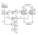
- each line 10 and 11 may represent a single line or a plurality of parallel lines depending upon whether the data transfer is serial or parallel.
- Each line 10 and 11 includes a respective register 12, 13 for temporary buffering of the data in each direction, the register 12 being the data output register (DOR) and the register 13 being the data input register (DIR).
- the registers 12 and 13 hold the information in parallel form. Registers such as the DOR 12 and the DIR 13 commonly form a part of the interface between a computer and a display terminal and may therefore be regarded as conventional items.
- Respective sensors 14 and 15 monitor the information content of the registers 12 and 13 over the lines 16 and 17 respectively, and each is arranged to provide an output signal in the form of a short pulse on a respective line 18 and 19 when the data changes.
- Each sensor 14 and 15 may, for example, comprise an OR gate having a plurality of parallel inputs each connected to a respective bit position of its associated register 12 or 13, the lines 16 and 17 therefore actually consisting of a plurality of parallel lines.
- the output of each OR gate will go high when the information in the associated DOR 12 or DIR 13 is modified, and this rise at the output of the OR gate may be used to generate the short pulse referred to above, for example using a monostable multivibrator.
- the output line 18 of the sensor 14 is connected to a counter 20 which, upon receipt of a pulse from the sensor 14, is loaded (set) to an initial count value held in a count register 21.
- the counter 20 thereafter immediately and automatically begins to count down to zero at a rate determined by an internal clock (not shown). When the counter reaches zero it provides an output signal on a line 22.
- the output line 19 of the sensor 15 is connected to an audible alarm circuit 23 via a logic gate 24.
- the gate 24, which may be an AND gate, is normally closed to signals on the line 19 but is enabled by the presence of a signal on the line 22.
- the alarm circuit 23 responds to a pulse from the sensor 15 by providing a short audible "buzz", "beep” or other desired sound.
- the above circuit operates as follows. When a terminal interrupt key or other interrupt device is pressed or actuated by the terminal user the data in the DOR 12 changes. This change is detected by the sensor 14 and the short pulse thereby provided on the line 18 loads the counter 20 from the register 21. The counter 20 then immediately and automatically counts down to zero.
- the sensor 15 also has a further output line 25.
- This line 25 provides precisely the same short pulse as the line 19 but it is applied instead to the counter 20. The latter responds to this pulse in the same way as it responds to a pulse on the line 18 from the sensor 14; i.e. the counter is loaded with the initial count value held in the register 21 and automatically counts down to zero.
- the reason for this further output 25 is to prevent repeated sounding of the alarm 23 by a rapid succession of computer responses (e.g. write operations) which occur after the counter 20 has reached zero but in reply to only a single original interrupt.
- the gate 24 would normally be permanently enabled by the line 22 so that each change in the DIR 13 will result in an audible signal.
- the line 25 thus provides that the counter 20 is reset to the initial count value after each successive computer response so that the latter will only sound the alarm if it follows the previous response by more than the time period defined by the initial count value held in the register 21.
- the pulse on the line 25 may be subject to a slight extra delay if necessary, although it is expected that normal circuit delays will be sufficient to provide the required sequence of operations.
- every key is an interrupt key.
- the computer will usually not write to the display until after the (ENTER) key is pressed. It therefore does not matter than the Y, E and S keys caused the counter 20 to be set when each was pressed since the interrupt of interest, the pressing of the (ENTER) key, will effect the final setting of the counter and the timing will begin at that point.
- terminals which have a "clicker” feature such as the IBM 3270 series, can conveniently use this in place of or as the final audible output of the alarm 23.
Landscapes
- Engineering & Computer Science (AREA)
- General Engineering & Computer Science (AREA)
- Theoretical Computer Science (AREA)
- Human Computer Interaction (AREA)
- Physics & Mathematics (AREA)
- General Physics & Mathematics (AREA)
- Debugging And Monitoring (AREA)
- Input From Keyboards Or The Like (AREA)
- Digital Computer Display Output (AREA)
Claims (3)
Priority Applications (4)
| Application Number | Priority Date | Filing Date | Title |
|---|---|---|---|
| EP83301869A EP0121016B1 (de) | 1983-03-31 | 1983-03-31 | Anzeigeterminal |
| DE8383301869T DE3367291D1 (en) | 1983-03-31 | 1983-03-31 | Display terminal |
| JP59000133A JPS59184938A (ja) | 1983-03-31 | 1984-01-05 | 通報装置 |
| US06/586,608 US4636770A (en) | 1983-03-31 | 1984-03-06 | Display terminal |
Applications Claiming Priority (1)
| Application Number | Priority Date | Filing Date | Title |
|---|---|---|---|
| EP83301869A EP0121016B1 (de) | 1983-03-31 | 1983-03-31 | Anzeigeterminal |
Publications (2)
| Publication Number | Publication Date |
|---|---|
| EP0121016A1 EP0121016A1 (de) | 1984-10-10 |
| EP0121016B1 true EP0121016B1 (de) | 1986-10-29 |
Family
ID=8191110
Family Applications (1)
| Application Number | Title | Priority Date | Filing Date |
|---|---|---|---|
| EP83301869A Expired EP0121016B1 (de) | 1983-03-31 | 1983-03-31 | Anzeigeterminal |
Country Status (4)
| Country | Link |
|---|---|
| US (1) | US4636770A (de) |
| EP (1) | EP0121016B1 (de) |
| JP (1) | JPS59184938A (de) |
| DE (1) | DE3367291D1 (de) |
Families Citing this family (2)
| Publication number | Priority date | Publication date | Assignee | Title |
|---|---|---|---|---|
| GB2403822B (en) * | 2003-07-07 | 2006-05-10 | Advanced Risc Mach Ltd | Data processing apparatus and method for handling interrupts |
| KR101262846B1 (ko) * | 2009-12-15 | 2013-05-10 | 한국전자통신연구원 | 임베디드 단말 성능 측정 장치 및 방법 |
Family Cites Families (11)
| Publication number | Priority date | Publication date | Assignee | Title |
|---|---|---|---|---|
| US3820105A (en) * | 1970-09-22 | 1974-06-25 | F Assmus | Electric signaling device for alarm clocks |
| US3778809A (en) * | 1971-04-05 | 1973-12-11 | J Hawes | Timer controlled alarm system |
| DE2143791A1 (de) * | 1971-09-01 | 1973-03-08 | Siemens Ag | Anordnung zur ueberwachung der uebertragung von daten |
| US3916090A (en) * | 1974-04-08 | 1975-10-28 | Teletype Corp | Intracommunication system for a communications terminal |
| JPS5127038A (en) * | 1974-08-30 | 1976-03-06 | Hitachi Ltd | Uotsuchi dogu taimaa |
| US4062007A (en) * | 1976-09-17 | 1977-12-06 | P. R. Mallory & Co. Inc. | Solid-state delay timed switching circuit |
| JPS5371545A (en) * | 1976-12-08 | 1978-06-26 | Hitachi Ltd | Multiprocessor |
| US4161787A (en) * | 1977-11-04 | 1979-07-17 | Motorola, Inc. | Programmable timer module coupled to microprocessor system |
| DE2834351C3 (de) * | 1978-08-04 | 1988-09-08 | Bauknecht Hausgeräte GmbH, 7000 Stuttgart | Programmwahleinrichtung |
| US4463416A (en) * | 1979-08-06 | 1984-07-31 | Ball Corporation | Programmable automatic controller |
| US4364655A (en) * | 1981-02-19 | 1982-12-21 | Parker Russell A | Photographic darkroom control system with timing means |
-
1983
- 1983-03-31 DE DE8383301869T patent/DE3367291D1/de not_active Expired
- 1983-03-31 EP EP83301869A patent/EP0121016B1/de not_active Expired
-
1984
- 1984-01-05 JP JP59000133A patent/JPS59184938A/ja active Pending
- 1984-03-06 US US06/586,608 patent/US4636770A/en not_active Expired - Lifetime
Also Published As
| Publication number | Publication date |
|---|---|
| JPS59184938A (ja) | 1984-10-20 |
| DE3367291D1 (en) | 1986-12-04 |
| US4636770A (en) | 1987-01-13 |
| EP0121016A1 (de) | 1984-10-10 |
Similar Documents
| Publication | Publication Date | Title |
|---|---|---|
| US4636770A (en) | Display terminal | |
| US3340515A (en) | Data buffering for time related measured data transmitted asynchronously | |
| JPS55127652A (en) | Mutual supervision system between computers | |
| US5495616A (en) | Processor system with interrupt discrimination | |
| JPS55116164A (en) | Information retrieval unit | |
| JPH05282244A (ja) | 情報処理装置 | |
| JPS60258656A (ja) | マイクロプロセツサリセツト回路 | |
| SU877549A1 (ru) | Система дл обработки информации с контролем | |
| JPS62214974A (ja) | プリンタ装置 | |
| SU1539819A1 (ru) | Устройство дл контрол работы оператора | |
| SU972499A2 (ru) | Устройство дл управлени вводом информации в электронную вычислительную машину | |
| JPH0477813A (ja) | キーボード | |
| SU1485265A1 (ru) | Устройство для моделирования систем массового обслуживания | |
| JP2844656B2 (ja) | 割込制御回路 | |
| SE8902718D0 (sv) | Asynkron avbrottsarbitrerare | |
| SU1520531A1 (ru) | Устройство дл сопр жени ЭВМ с абонентами | |
| SU1171776A1 (ru) | Устройство дл ввода информации | |
| SU1659988A2 (ru) | Устройство дл контрол параметров | |
| JPS57728A (en) | Monitoring device | |
| SU1087962A1 (ru) | Устройство контрол параметров | |
| SU1406588A1 (ru) | Устройство дл ввода информации от абонентов | |
| JPH043553B2 (de) | ||
| JPH0638593B2 (ja) | リセット信号判別回路 | |
| JPS5451754A (en) | Process system for data transmission error | |
| JPS633332B2 (de) |
Legal Events
| Date | Code | Title | Description |
|---|---|---|---|
| PUAI | Public reference made under article 153(3) epc to a published international application that has entered the european phase |
Free format text: ORIGINAL CODE: 0009012 |
|
| AK | Designated contracting states |
Kind code of ref document: A1 Designated state(s): DE FR GB Designated state(s): DE FR GB |
|
| 17P | Request for examination filed |
Effective date: 19841123 |
|
| 17Q | First examination report despatched |
Effective date: 19860117 |
|
| GRAA | (expected) grant |
Free format text: ORIGINAL CODE: 0009210 |
|
| AK | Designated contracting states |
Kind code of ref document: B1 Designated state(s): DE FR GB |
|
| REF | Corresponds to: |
Ref document number: 3367291 Country of ref document: DE Date of ref document: 19861204 |
|
| ET | Fr: translation filed | ||
| PLBE | No opposition filed within time limit |
Free format text: ORIGINAL CODE: 0009261 |
|
| STAA | Information on the status of an ep patent application or granted ep patent |
Free format text: STATUS: NO OPPOSITION FILED WITHIN TIME LIMIT |
|
| 26N | No opposition filed | ||
| PGFP | Annual fee paid to national office [announced via postgrant information from national office to epo] |
Ref country code: FR Payment date: 19960307 Year of fee payment: 14 |
|
| PG25 | Lapsed in a contracting state [announced via postgrant information from national office to epo] |
Ref country code: FR Free format text: LAPSE BECAUSE OF NON-PAYMENT OF DUE FEES Effective date: 19971128 |
|
| REG | Reference to a national code |
Ref country code: FR Ref legal event code: ST |
|
| REG | Reference to a national code |
Ref country code: GB Ref legal event code: IF02 |
|
| PGFP | Annual fee paid to national office [announced via postgrant information from national office to epo] |
Ref country code: GB Payment date: 20020306 Year of fee payment: 20 |
|
| PGFP | Annual fee paid to national office [announced via postgrant information from national office to epo] |
Ref country code: DE Payment date: 20020320 Year of fee payment: 20 |
|
| PG25 | Lapsed in a contracting state [announced via postgrant information from national office to epo] |
Ref country code: GB Free format text: LAPSE BECAUSE OF EXPIRATION OF PROTECTION Effective date: 20030330 |
|
| REG | Reference to a national code |
Ref country code: GB Ref legal event code: PE20 |