EP0121705A2 - Hydraulisches Steuersystem für automatische Getriebe mit stossloser 4-3- und 2-3-Schaltung - Google Patents
Hydraulisches Steuersystem für automatische Getriebe mit stossloser 4-3- und 2-3-Schaltung Download PDFInfo
- Publication number
- EP0121705A2 EP0121705A2 EP84101803A EP84101803A EP0121705A2 EP 0121705 A2 EP0121705 A2 EP 0121705A2 EP 84101803 A EP84101803 A EP 84101803A EP 84101803 A EP84101803 A EP 84101803A EP 0121705 A2 EP0121705 A2 EP 0121705A2
- Authority
- EP
- European Patent Office
- Prior art keywords
- fluid
- speed ratio
- shifting
- supplied
- pressure
- Prior art date
- Legal status (The legal status is an assumption and is not a legal conclusion. Google has not performed a legal analysis and makes no representation as to the accuracy of the status listed.)
- Withdrawn
Links
- 230000005540 biological transmission Effects 0.000 title claims description 18
- 239000012530 fluid Substances 0.000 claims abstract description 61
- 239000003112 inhibitor Substances 0.000 description 3
- 238000010586 diagram Methods 0.000 description 1
- 230000000694 effects Effects 0.000 description 1
- 239000003607 modifier Substances 0.000 description 1
- 230000035939 shock Effects 0.000 description 1
Images



Classifications
-
- F—MECHANICAL ENGINEERING; LIGHTING; HEATING; WEAPONS; BLASTING
- F16—ENGINEERING ELEMENTS AND UNITS; GENERAL MEASURES FOR PRODUCING AND MAINTAINING EFFECTIVE FUNCTIONING OF MACHINES OR INSTALLATIONS; THERMAL INSULATION IN GENERAL
- F16H—GEARING
- F16H61/00—Control functions within control units of change-speed- or reversing-gearings for conveying rotary motion ; Control of exclusively fluid gearing, friction gearing, gearings with endless flexible members or other particular types of gearing
- F16H61/04—Smoothing ratio shift
- F16H61/06—Smoothing ratio shift by controlling rate of change of fluid pressure
- F16H61/065—Smoothing ratio shift by controlling rate of change of fluid pressure using fluid control means
- F16H61/068—Smoothing ratio shift by controlling rate of change of fluid pressure using fluid control means using an orifice control valve
-
- F—MECHANICAL ENGINEERING; LIGHTING; HEATING; WEAPONS; BLASTING
- F16—ENGINEERING ELEMENTS AND UNITS; GENERAL MEASURES FOR PRODUCING AND MAINTAINING EFFECTIVE FUNCTIONING OF MACHINES OR INSTALLATIONS; THERMAL INSULATION IN GENERAL
- F16H—GEARING
- F16H61/00—Control functions within control units of change-speed- or reversing-gearings for conveying rotary motion ; Control of exclusively fluid gearing, friction gearing, gearings with endless flexible members or other particular types of gearing
- F16H61/04—Smoothing ratio shift
- F16H61/08—Timing control
Definitions
- the present invention relates to a hydraulic control system for an automatic transmission.
- a brake In a known four speed automatic transmission, a brake must be released in timed relationship with the engagement of a first clutch during 2-3 shifting, while the same brake must be released in timed relationship with the engagement of a second clutch during 4-3 shifting.
- a hydraulic control system for an automatic transmission which to provides at least three forward speed ratios and shiftable to a n + 2 th speed ratio, a n + 1 th speed ratio and a n th speed ratio
- the automatic transmission including a first, a second and a third friction units, the n + 2 th speed ratio being established when fluid pressure is supplied to a fluid chamber of the first friction unit and fluid pressure is discharged from both of fluid chambers of the second and third friction units, the n + 1 th speed ratio being established when fluid pressure is supplied to all of fluid chambers of the first, second and third friction units, and the n th speed ratio being established when fluid pressure is supplied to the third friction unit and fluid pressure is discharged from fluid chambers of the first and second friction units,
- the hydraulic control system comprising:
- An object of the present invention is to improve an automatic transmission wherein one friction unit is actuated during a shifting from a n th speed ratio to a n + 1 th speed ratio and also during a shifting from a n + 2 th speed ratio to the n + 1 th speed ratio by providing a hydraulic control system wherein fluid pressure is supplied to this friction unit via different fluid flow paths so as to actuate the friction unit at different timings which are optimum for the two shiftings, respectively, where, n is a positive integer.
- a power transmission mechanism of a four forward speed and one reverse speed automatic transmission having an overdrive comprises an input shaft I operatively connected via a torque converter-T/C to an engine output shaft E of an engine which has a throttle which opens in degrees, an output-shaft 0 operatively connected to road wheels, only one being shown, via a final drive, not shown.
- a first planetary gear set G1 and a second planetary gear set G2 are connected between the input and output shafts I and 0.
- a plurality of fluid operated friction units are provided which are made operative and inoperative for producing a plurality of speed ratios between the input shaft I and output shaft 0.
- the fluid operated friction units include a first clutch C1, a second clutch C2, a third clutch C3, a first brake B1, a second brake B2, and a one-way clutch OWC.
- the first planetary gear set G1 comprises a sun gear S1, an internal gear R1, a carrier PC1 carrying pinion gears P1 meshing simultaneously both the gears S1 and R1.
- the planetary gear set G2 comprises a sun gear S2, an internal gear R2 and a carrier PC2 carrying pinion gears P2 meshing simultaneouly both gears S2 and R2.
- the carrier PC1 is connectable via the clutch C1 with the input shaft I
- the sun gear S1 is connectable via the clutch C2 with the input shaft I.
- the carrier PC1 is connectable via the clutch C3 with the internal gear R2.
- the sun gear S2 is constantly connected with the input shaft I.
- the internal gear R1 and carrier PC2 are constantly connected with the output shaft 0.
- the brake B.1 is arranged to ⁇ anchor the carrier PC1.
- the brake B2 is arranged to anchor the sun gear S1.
- the one-way clutch OWC is so constructed that it allows forward rotation (i.e., the same rotation as that of the engine output shaft E), but prevents reverse rotation (i.e., the rotation opposite to the forward rotation). Thus, it acts as a brake only during reverse rotation.
- each of the rotary elements (S1, S2, R1, R2, PC1, and PC2) of the planetary gear sets G1 and G2 can be varied by actuating selected one or combination of the clutches C1, C2 and C3, brake B1, (one-way clutch OWC) and brake B2, thus varying the revolution speed of the output shaft 0 relative to that of the input shaft I.
- the four forward speed ratios and one reverse speed ratio are produced if the clutches C1, C2 and C3 and brakes B1 and B2 are engaged in the manner as shown in the following Table.
- a sign "o" denotes actuation state of the clutch or brake
- ⁇ 1 and ⁇ 2 respectively denote ratios of number of teeth of the internal gears R1 and R2 to number of teeth of the corresponding sun gears S1 and S2.
- a gear ratio is a ratio of the revolution number of the input shaft I to that of the output shaft 0.
- OWC the brake B1
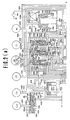
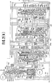
- This hydraulic control system comprises a regulator valve 2, a manual valve 4, a throttle valve 6, a throttle fail safe valve 8, a throttle modulator valve 10, a pressure modifier valve 12, a cut back valve 14, a line pressure booster valve 16, a governor valve 18, a 1-2 shift valve 20, a 2-3 shift valve 22, a servo release changeover valve 23, a 3-4 shift valve 24, a 2-4 timing valve 26, a 2-3 timing valve 28, a 3-4 timing valve 30, a 3-2 timing valve 32, a first manual range pressure reducing valve 34, a torque converter pressure reducing valve 36, a 1-2 accumulator 38, a 4-3 accumulator 40, and an overdrive inhibitor solenoid 42.
- These valves are interconnected as shown in Figs.
- the brake B2 has a servo apply chamber S/A, i.e., an oil pressure chamber designed to apply the brake when pressurized, and a servo release chamber S/R, i.e., an oil pressure chamber designed to release the brake when pressurized.
- the brake B2 is released when the pressure is supplied to the servo release chamber S/R irrespective of the supply of oil pressure to the servo apply chamber S/A.
- the overdrive inhibitor solenoid 42 is electrically connected with an overdrive inhibitor switch SW.
- the hydraulic control system is substantially the same as a prior proposed hydraulic control system disclosed in copending European Pat. Appln. 83107503.1 filed on July 29, 1983 by Nissan Motor Co., Ltd. (our ref.: EP054-83).
- This copening application is incorporated hereby by reference in its entirety. Particulary, attention is directed to Figs. 2(a), 2(b) and 2(c) and the description along therewith.
- the hydraulic control system of the present application is different from the prior proposed hydraulic control system in that a servo release chamber S/R is selectively connectable with a first oil conduit 434 leading to the clutch C2 or a second oil conduit 442 leading to the clutch C3 and an orifice 617 is provided in an oil conduit 412 near a port 124h of the 3-4 shift valve 24 as opposed to the prior proposed hydraulic control system wherein the servo release chamber S/R for the brake B2 is connectable with the first oil conduit 434 only.
- the servo release changeover valve 23 comprises a valve bore 123 formed with five ports 123a to 123e, a spool 223 having formed thereon two -lands 223a and 223b slidably disposed in the valve bore 123, and a spring 323 biasing the spool 223 downward as viewed in Fig. 2(d).
- Fig. 3 wherein the servo release changeover valve 23 is illustrated with the 2-3 shift valve 22 and the 3-4 shift valve 24.
- the port 122f of the 2-3 shift valve 22 is connected via an orifice 616 with an oil conduit 432 which is supplied with the line pressure when the 1-2 shift valve (not shown in Fig. 3) assumes the upshift position thereof.
- the port 122f of the 2-3 shift valve 22 is allowed to communicate with the port 122g when the 2-3 shift valve 22 assumes the upshift position thereof (as indicated by the left half thereof as viewed in Fig. 3).
- This port 122g is connected via an oil conduit 434 with the clutch C2.
- the ports 123a and 123d of the servo release changeover valve 23 are connected with the before mentioned oil conduit 442, the ports 123b and 123e are connected with the before mentioned oil conduit 434, and the port 123c is connected with the oil conduit 435 communicating with the before mentioned oil conduit 437. Next, the operation is described.
- the operation during 2-3 shifting is described.
- the 1-2 shift valve 20 not shown in Fig. 3 assumes the upshift position thereof and the line pressure is supplied to the oil conduit 432. Therefore, the line pressure is supplied to the servo apply chamber S/A.
- the 3-4 shift valve 24 assumes the downshift position, too, as indicated by the right half thereof as viewed in Fig. 3, supplying the line pressure in the oil conduit 412 to the clutch C3 via the port 124h, port 124g and oil conduit 442.
- the 2nd speed ratio is established wherein the clutch C3 and brake B2 are engaged.
- the 2-3 shift valve 22 and 3-4 shift valve 24 assume the upshift positions thereof as indicated by the left halves thereof as viewed in Fig. 3.
- the oil pressure in the oil conduit 432 is supplied to the servo apply chamber S/A and the oil pressure in the oil conduit 434 is supplied to the clutch C2, establishing the 4th speed ratio wherein the brake B2 and clutch C2 are engaged.
- the oil pressure in the oil conduit 434 is supplied, via the ports 123b and 123c of the servo release changeover valve 23, oil conduits 435 and 437, to the port 124e of the 3-4 shift valve.
- the port 124e is closed by the 3-4 shift valve 24 which stays in the upshift position thereof, thus preventing the supply of oil pressure to the servo release chamber S/R.
- the 3-4 shift 24 shifts from the upshift position thereof as indicated the left half thereof as viewed in Fig. 3 to the downshift position thereof as indicated by the right half thereof as viewed in Fig. 3, the port 124g is allowed to communicate with the port 124h. This causes the line pressure in the oil conduit 412 to be supplied to the oil conduit 442 via the orifice 617. This results in the engagement of the clutch C3.
- the oil pressure in the oil conduit 442 acts in the port 123a of the servo release changeover valve 23, urging it to shift from the up position thereof as indicated by the left half thereof as viewed in Fig. 3 to the down position ereo as viewed in ig. 3.
- the servo release changeover valve 23 shifts to the down position owing to the action of the spring 323 when oil pressure starts acting in the port 123a.
- This causes the port 123c to communicate with the port 123d, thus allowing the line pressure in the oil conduit 442 to be supplied to the oil conduit 435.
- the oil pressure in the oil conduit 435 is supplied, via the oil conduit 437, ports 124e and 124d of the 3-4 shift valve 24 and oil conduit 444, to the servo release chamber S/R. This results in the release of the brake B2.
- the 3rd speed ratio wherein the clutches C2 and C3 are engaged is established.
- the oil pressure supplied to the clutch C3 and the servo release chamber S/R is supplied from the oil conduit 412 via the common orifice 617. Therefore, substantially the same oil pressure acts in the clutch C3 and in the servo release chamber S/R, allowing the clutch C3 to be engaged simultaneously with the release of the brake B2. Accordingly, the engagement of the clutch C3 is effected always in optimum timed relationship with the release of the brake B2.
- the oil pressure is supplied via the orifice 616 to the clutch C2 and the servo release chamber S/R during 2-3 shifting, while the oil- pressure is supplied via the orifice 617 to the clutch C3 and servo release chamber S/R during 4-3 shifting.
- the engagement of the clutch is effected always in the optimum timed relationship with the release of the brake in each of the shiftings.
- the oil pressure is supplied to the servo release - chambler S/R for the brake B2 via the first flow path 434-435-437-444 at the flow rate determined by the orifice 616 during 2-3 shifting and via the second flow path 412-442-435-437-444 at the flow rate determined by the orifice 412 during 4-3 shifting.
Landscapes
- Engineering & Computer Science (AREA)
- General Engineering & Computer Science (AREA)
- Physics & Mathematics (AREA)
- Fluid Mechanics (AREA)
- Mechanical Engineering (AREA)
- Control Of Transmission Device (AREA)
Applications Claiming Priority (2)
| Application Number | Priority Date | Filing Date | Title |
|---|---|---|---|
| JP38354/83 | 1983-03-10 | ||
| JP58038354A JPS59164443A (ja) | 1983-03-10 | 1983-03-10 | 自動変速機の油圧制御装置 |
Publications (2)
| Publication Number | Publication Date |
|---|---|
| EP0121705A2 true EP0121705A2 (de) | 1984-10-17 |
| EP0121705A3 EP0121705A3 (de) | 1984-12-05 |
Family
ID=12522938
Family Applications (1)
| Application Number | Title | Priority Date | Filing Date |
|---|---|---|---|
| EP84101803A Withdrawn EP0121705A3 (de) | 1983-03-10 | 1984-02-21 | Hydraulisches Steuersystem für automatische Getriebe mit stossloser 4-3- und 2-3-Schaltung |
Country Status (3)
| Country | Link |
|---|---|
| US (1) | US4555964A (de) |
| EP (1) | EP0121705A3 (de) |
| JP (1) | JPS59164443A (de) |
Cited By (3)
| Publication number | Priority date | Publication date | Assignee | Title |
|---|---|---|---|---|
| US4555964A (en) * | 1983-03-10 | 1985-12-03 | Nissan Motor Co., Ltd. | Hydraulic control system for automatic transmission with shockless 4-3 shifting as well as shockless 2-3 shifting |
| EP0422844A3 (en) * | 1989-10-09 | 1992-02-26 | Toyota Jidosha Kabushiki Kaisha | Hydraulic pressure control device with parallel pressure supply passages for certain one friction engaging means |
| EP0356036A3 (de) * | 1988-08-02 | 1992-03-04 | Toyota Jidosha Kabushiki Kaisha | Hydraulische Steuerung für ein automatisches Fahrzeuggetriebe mit einer Kupplung mit zwei Schaltzuständen und zwei parallelen Druckversorgungsleitungen dafür |
Families Citing this family (12)
| Publication number | Priority date | Publication date | Assignee | Title |
|---|---|---|---|---|
| US4719822A (en) * | 1984-04-04 | 1988-01-19 | Toyota Jidosha Kabushiki Kaisha | Hydraulic pressure control apparatus for use in an automotive transmission |
| FR2570458B1 (fr) * | 1984-09-18 | 1990-03-02 | Renault | Dispositif et procedes de commande d'une transmission automatique a quatre rapports |
| US4727774A (en) * | 1985-07-31 | 1988-03-01 | Aisin-Warner Kabushiki Kaisha | Cut-back pressure control device for multi-speed automatic transmission |
| US4722250A (en) * | 1985-07-31 | 1988-02-02 | Aisin-Warner Kabushiki Kaisha | Accumulator back pressure control apparatus for automatic transmission |
| US4722251A (en) * | 1985-07-31 | 1988-02-02 | Aisin-Warner Kabushiki Kaisha | Hydraulic circuit for controlling an automatic transmission |
| DE3528789C1 (de) * | 1985-08-10 | 1986-10-23 | Daimler-Benz Ag, 7000 Stuttgart | Druckregelvorrichtung mit einem Daempfungsorgan fuer einen Steuerdruck eines automatischen Gangwechselgetriebes |
| JPH0820014B2 (ja) * | 1987-10-30 | 1996-03-04 | 日産自動車株式会社 | 自動変速機の変速制御装置 |
| US5043727A (en) * | 1989-02-03 | 1991-08-27 | Sanshin Kogyo Kabushiki Kaisha | Display system for marine vessel |
| JPH05332424A (ja) * | 1992-06-03 | 1993-12-14 | Jatco Corp | 自動変速機の油圧制御装置 |
| US5305665A (en) * | 1992-09-02 | 1994-04-26 | Jatco Corporation | Speed change control device of automatic transmission |
| GB2278654B (en) * | 1993-06-03 | 1997-11-19 | Toyota Motor Co Ltd | Shift control system for automatic transmission |
| EP0685666B1 (de) * | 1994-06-02 | 1999-10-27 | Aisin Aw Co., Ltd. | Steuerungssystem für Automatikgetriebe |
Family Cites Families (18)
| Publication number | Priority date | Publication date | Assignee | Title |
|---|---|---|---|---|
| US3656373A (en) * | 1968-10-31 | 1972-04-18 | Tetsuo Shimosaki | Control system for an automatic transmission |
| US3830258A (en) * | 1969-04-25 | 1974-08-20 | Borg Warner Ltd | Transmission control mechanism |
| US3728915A (en) * | 1969-10-27 | 1973-04-24 | Gen Motors Corp | Transmission shift control |
| JPS4820655B1 (de) * | 1970-02-12 | 1973-06-22 | ||
| JPS4841491B1 (de) * | 1970-07-31 | 1973-12-06 | ||
| US3896685A (en) * | 1973-09-12 | 1975-07-29 | Gen Motors Corp | Transmission control for a transmission having one drive establishing device for two independent drive functions |
| JPS5174167A (en) * | 1974-12-23 | 1976-06-26 | Toyota Motor Co Ltd | Jidohensokukino yuatsuseigyosochi |
| JPS5930942B2 (ja) * | 1978-08-30 | 1984-07-30 | 日産自動車株式会社 | 自動変速機のダウンシフト弁 |
| JPS5948901B2 (ja) * | 1978-09-29 | 1984-11-29 | 日産自動車株式会社 | 自動変速機の変速点制御装置 |
| JPS55149455A (en) * | 1979-05-10 | 1980-11-20 | Aisin Warner Ltd | Timing valve for automatic transmission controller |
| US4347765A (en) * | 1979-10-05 | 1982-09-07 | Ford Motor Company | Multiple ratio overdrive transmission |
| US4413536A (en) * | 1980-08-11 | 1983-11-08 | Ford Motor Company | Automatic transaxle control system |
| JPS57144338A (en) * | 1981-02-26 | 1982-09-06 | Nissan Motor Co Ltd | Shifter for automatic gear change |
| JPS57144339A (en) * | 1981-02-28 | 1982-09-06 | Nissan Motor Co Ltd | Shifter for automatic gear change |
| US4446759A (en) * | 1981-10-02 | 1984-05-08 | Ford Motor Company | Clutch stroke control metering valve for an automatic transmission |
| US4468989A (en) * | 1981-11-09 | 1984-09-04 | Ford Motor Company | Power transmission mechanism with a hydrokinetic torque converter having a lockup clutch |
| JPS58131458A (ja) * | 1982-01-28 | 1983-08-05 | Aisin Warner Ltd | 車両用自動変速機の油圧制御装置 |
| JPS59164443A (ja) * | 1983-03-10 | 1984-09-17 | Nissan Motor Co Ltd | 自動変速機の油圧制御装置 |
-
1983
- 1983-03-10 JP JP58038354A patent/JPS59164443A/ja active Pending
-
1984
- 1984-02-17 US US06/581,506 patent/US4555964A/en not_active Expired - Fee Related
- 1984-02-21 EP EP84101803A patent/EP0121705A3/de not_active Withdrawn
Cited By (3)
| Publication number | Priority date | Publication date | Assignee | Title |
|---|---|---|---|---|
| US4555964A (en) * | 1983-03-10 | 1985-12-03 | Nissan Motor Co., Ltd. | Hydraulic control system for automatic transmission with shockless 4-3 shifting as well as shockless 2-3 shifting |
| EP0356036A3 (de) * | 1988-08-02 | 1992-03-04 | Toyota Jidosha Kabushiki Kaisha | Hydraulische Steuerung für ein automatisches Fahrzeuggetriebe mit einer Kupplung mit zwei Schaltzuständen und zwei parallelen Druckversorgungsleitungen dafür |
| EP0422844A3 (en) * | 1989-10-09 | 1992-02-26 | Toyota Jidosha Kabushiki Kaisha | Hydraulic pressure control device with parallel pressure supply passages for certain one friction engaging means |
Also Published As
| Publication number | Publication date |
|---|---|
| JPS59164443A (ja) | 1984-09-17 |
| EP0121705A3 (de) | 1984-12-05 |
| US4555964A (en) | 1985-12-03 |
Similar Documents
| Publication | Publication Date | Title |
|---|---|---|
| US4637281A (en) | Control valve system for a four-speed automatic power transmission transaxle | |
| US3706240A (en) | Four-speed ratio automatic power transmission mechanism | |
| US4555964A (en) | Hydraulic control system for automatic transmission with shockless 4-3 shifting as well as shockless 2-3 shifting | |
| EP0123046B1 (de) | Hydraulisches Steuersystem für automatische Getriebe mit stossloser 4-2-Schaltung | |
| JPS59155649A (ja) | 自動変速機の油圧制御装置 | |
| US4607542A (en) | Hydraulic control system for automatic transmission with shockless 4-3 and 4-2 shiftings | |
| US4367812A (en) | Control apparatus for torque converter direct coupling clutch in automatic transmissions | |
| US5674153A (en) | Hydraulic pressure control system of an automatic transmission for vehicle | |
| US5536216A (en) | Hydraulic pressure control system of an automatic transmission for vehicle | |
| US5010788A (en) | Automatic automotive transmission having 4-2 downshift sequence valve | |
| EP0678690B1 (de) | Hydraulische Steuerung für ein automatisches Viergang-Kraftfahrzeuggetriebe | |
| EP0103751A2 (de) | Hydraulisches Steuersystem für automatische Getriebe | |
| JPH01116345A (ja) | 自動変速機の変速制御装置 | |
| JPH01116351A (ja) | 自動変速機の油圧緩和装置 | |
| JPH01116373A (ja) | 自動変速機のロックアップ制御装置 | |
| EP0314192B1 (de) | Reibelementanpressdruck- und -Zeit-Steuerung für ein Automatikgetriebe | |
| US5042329A (en) | Control system for automatic transmission featuring improved downshifting characteristics with overdrive inhibitor | |
| JPS61256047A (ja) | 車両用自動変速機の油圧制御装置 | |
| JPH02225869A (ja) | 自動変速機の油圧制御装置 | |
| US4951528A (en) | Shift control system for automatic transmission | |
| JPH01116337A (ja) | 自動変速機の変速制御装置 | |
| US4876925A (en) | Hydraulic control system for automatic automotive transmission | |
| KR100296267B1 (ko) | 자동변속기의유압제어시스템및변속제어방법 | |
| JPS62220751A (ja) | 自動変速機の制御装置 | |
| JPH01116350A (ja) | 自動変速機の変速制御装置 |
Legal Events
| Date | Code | Title | Description |
|---|---|---|---|
| PUAI | Public reference made under article 153(3) epc to a published international application that has entered the european phase |
Free format text: ORIGINAL CODE: 0009012 |
|
| PUAL | Search report despatched |
Free format text: ORIGINAL CODE: 0009013 |
|
| 17P | Request for examination filed |
Effective date: 19840221 |
|
| AK | Designated contracting states |
Designated state(s): DE FR GB |
|
| AK | Designated contracting states |
Designated state(s): DE FR GB |
|
| RAP1 | Party data changed (applicant data changed or rights of an application transferred) |
Owner name: NISSAN MOTOR CO., LTD. |
|
| 17Q | First examination report despatched |
Effective date: 19860130 |
|
| D17Q | First examination report despatched (deleted) | ||
| STAA | Information on the status of an ep patent application or granted ep patent |
Free format text: STATUS: THE APPLICATION IS DEEMED TO BE WITHDRAWN |
|
| 18D | Application deemed to be withdrawn |
Effective date: 19880118 |
|
| RIN1 | Information on inventor provided before grant (corrected) |
Inventor name: SUGANO, KAZUHIKO |