EP0123264A2 - Système de bâtiment et ses composants - Google Patents
Système de bâtiment et ses composants Download PDFInfo
- Publication number
- EP0123264A2 EP0123264A2 EP84104368A EP84104368A EP0123264A2 EP 0123264 A2 EP0123264 A2 EP 0123264A2 EP 84104368 A EP84104368 A EP 84104368A EP 84104368 A EP84104368 A EP 84104368A EP 0123264 A2 EP0123264 A2 EP 0123264A2
- Authority
- EP
- European Patent Office
- Prior art keywords
- mold
- elements
- face portion
- flange
- face
- Prior art date
- Legal status (The legal status is an assumption and is not a legal conclusion. Google has not performed a legal analysis and makes no representation as to the accuracy of the status listed.)
- Withdrawn
Links
Images


Classifications
-
- E—FIXED CONSTRUCTIONS
- E04—BUILDING
- E04G—SCAFFOLDING; FORMS; SHUTTERING; BUILDING IMPLEMENTS OR AIDS, OR THEIR USE; HANDLING BUILDING MATERIALS ON THE SITE; REPAIRING, BREAKING-UP OR OTHER WORK ON EXISTING BUILDINGS
- E04G13/00—Falsework, forms, or shutterings for particular parts of buildings, e.g. stairs, steps, cornices, balconies foundations, sills
-
- E—FIXED CONSTRUCTIONS
- E04—BUILDING
- E04G—SCAFFOLDING; FORMS; SHUTTERING; BUILDING IMPLEMENTS OR AIDS, OR THEIR USE; HANDLING BUILDING MATERIALS ON THE SITE; REPAIRING, BREAKING-UP OR OTHER WORK ON EXISTING BUILDINGS
- E04G11/00—Forms, shutterings, or falsework for making walls, floors, ceilings, or roofs
- E04G11/06—Forms, shutterings, or falsework for making walls, floors, ceilings, or roofs for walls, e.g. curved end panels for wall shutterings; filler elements for wall shutterings; shutterings for vertical ducts
- E04G11/08—Forms, which are completely dismantled after setting of the concrete and re-built for next pouring
- E04G11/10—Forms, which are completely dismantled after setting of the concrete and re-built for next pouring of elements without beams which are mounted during erection of the shuttering to brace or couple the elements
-
- E—FIXED CONSTRUCTIONS
- E04—BUILDING
- E04G—SCAFFOLDING; FORMS; SHUTTERING; BUILDING IMPLEMENTS OR AIDS, OR THEIR USE; HANDLING BUILDING MATERIALS ON THE SITE; REPAIRING, BREAKING-UP OR OTHER WORK ON EXISTING BUILDINGS
- E04G11/00—Forms, shutterings, or falsework for making walls, floors, ceilings, or roofs
- E04G11/36—Forms, shutterings, or falsework for making walls, floors, ceilings, or roofs for floors, ceilings, or roofs of plane or curved surfaces end formpanels for floor shutterings
- E04G11/48—Supporting structures for shutterings or frames for floors or roofs
-
- E—FIXED CONSTRUCTIONS
- E04—BUILDING
- E04G—SCAFFOLDING; FORMS; SHUTTERING; BUILDING IMPLEMENTS OR AIDS, OR THEIR USE; HANDLING BUILDING MATERIALS ON THE SITE; REPAIRING, BREAKING-UP OR OTHER WORK ON EXISTING BUILDINGS
- E04G17/00—Connecting or other auxiliary members for forms, falsework structures, or shutterings
- E04G17/001—Corner fastening or connecting means for forming or stiffening elements
-
- E—FIXED CONSTRUCTIONS
- E04—BUILDING
- E04G—SCAFFOLDING; FORMS; SHUTTERING; BUILDING IMPLEMENTS OR AIDS, OR THEIR USE; HANDLING BUILDING MATERIALS ON THE SITE; REPAIRING, BREAKING-UP OR OTHER WORK ON EXISTING BUILDINGS
- E04G9/00—Forming or shuttering elements for general use
- E04G9/02—Forming boards or similar elements
- E04G9/06—Forming boards or similar elements the form surface being of metal
-
- E—FIXED CONSTRUCTIONS
- E04—BUILDING
- E04G—SCAFFOLDING; FORMS; SHUTTERING; BUILDING IMPLEMENTS OR AIDS, OR THEIR USE; HANDLING BUILDING MATERIALS ON THE SITE; REPAIRING, BREAKING-UP OR OTHER WORK ON EXISTING BUILDINGS
- E04G9/00—Forming or shuttering elements for general use
- E04G9/02—Forming boards or similar elements
- E04G2009/028—Forming boards or similar elements with reinforcing ribs on the underside
Definitions
- the system of the present invention fills a vacuum in the construction. It fulfills a series of purposes which simplify the construction process of any type of structure, and also substantially reduces the cost of the process.
- Another object is that of providing monolithic structures which require less material and provide more endurance.
- Still another object is that of providing an extraordinary rapid construction system for enabling building of houses and the like at a favorable rate of at least three to one when compared to current building systems.
- Another object is that of providing the means for a low cost wholly predictable building operation to be implemented from conception to commissioning in a short time by a disciplined crew.
- Still another object is to provide a system which may be partially implemented for construction jobs involving minor additions or changes to existing structures or for providing partial structions to be finished with different materials such as for example, glass walls or thatched roofs, etc.
- Another objective is the provision of a building system capable of incorporating a great diversity of building materials, a wide selection of architectural designs and any desired combination of building foundations, supports for vaults or additional stories for housing heavy machinery, bearing walls in combination with non-bearing walls, etc.
- the system of the present invention relates to a mold formed by a multiplicity of panels to be assembled into which a castable material capable of setting to produce a load bearing structure may be poured.
- the present invention provides a system for monolithic construction of a structure which comprises an assembly of metal mold elements into which a castable material, hardenable to produce a load bearing structure may be poured, said mold assembly comprising at least one mold disassembly facilitating element selected from the following:
- the invention provides particularly shaped mold elements, particular arrangements of mold elements and particular devices of use in conjunction with the mold system.
- the system of the present invention further provides panels which can withstand the pressure excerted by cement or concrete in the fluid state.
- the elements of the system are also capable of being coupled together in a fluid-tight manner as a result of their method of construction and the particular type of novel nut and bolt system used.
- the invention further provides a ground pattern which permits un- or simi-skilled workers to lay out utility conduits and position walls with a minimum of supervision.
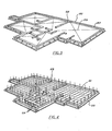
- a particular feature of the system of the present invention is the ease with which the forms into which concrete or cement is to be poured may be assembled and disassembled. Particular elements which facilitate the assembly and disassembly of the forms are described below. It will, however, be useful to provide a more general description of how these operations may be carried out.
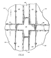
- a mold 100 defining the periphery of the foundation slab is assembled using mold elements. These have walls 200 and base portions 201. They are secured to the ground (as shown - Fig. 1) by driving metal stakes 203 through holes 202 and corresponding holes (not shown) in the base 200. Thereafter any rough patches in the ground encompassed by the mold wall may be levelled and a steel wire netting 101 laid (this is shown in position in Fig. 4 - but for convenience is not shown in Fig. 3). This netting acts as reinforcement for the concrete of the floor slab.
- a ground distribution pattern 108 made at a scale of 1:1 with regard to the dwelling is laid on the ground to-provide for a marking of the confines of each room as shown in Fig. 3.
- An element of the type used to construct the ground distribution pattern is shown in Fig. 27. This shows members 204 and 205 which mark the faces of the walls and a brace 206 to prevent distortion of the pattern in use. Also shown are hooks 207 whereby the member can be suspended from the walls 200 of the base mold element as shown in Fig. 3. After thorough marking has taken place, a upright metal rods 102 may be attached to the netting 101 along the lines of the walls.
- the plumbing network 104 as well as the electricity, air conditioning, gas supply and other networks are laid in their final desired locations, so as to have them embedded when concrete is poured. This is shown in Figure 4.
- the next step of the process is that of pouring concrete or cement to define a floor and the secure a base for the construction.
- the rods 102 naturally become embedded in this floor layer.
- the ground pattern is replaced in position as shown in Figure 5 and the positions of rods 102 and the conduits for utilities 104 are checked.
- This repositioning of the pattern also enables one to provide for spacer and positioning means to be attached to the concrete base so as to ensure the correct assembly of the metal mold forms into which concrete for the walls will be poured.
- spacer/positions means will be in the form of a simple U-shaped member which can be affixed to the concrete base between the pattern pieces for the inner and outer walls.
- the pattern may be suspended from the walls of the mold used to pour the concrete base.
- the pattern is removed from the concrete base.
- metal reinforcing netting 103 is attached to the uprights 102 to reinforce the walls as shown in Figure 6.
- the mold form elements 106 are assembled at both sides of the wirenetting 103 previously set up.
- the mold form assembly includes the lower surface of the roof and provision is made for frames for doors and windows or a corresponding space for then is allowed.
- L-shaped members as shown in Figure 26 along the lines which constitute the internal and external faces of all internal and external walls.
- These L-shaped members comprise "back" pieces 127 and bases 125 having holes l24 therein and are positioned with their bases 125 pointing inwards.
- the dimensions of the bases of the L-shaped members are such that they fit with the edge flanges of the elements of the mold forms.
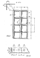
- the mold forms used for the walls are typically of the type shown in Figure 9.
- Such mold forms have a metal base 126, the side of which that is not visible in these figures being the side which forms the surface abutting the concrete once this has been poured.
- Welded to the base 126 are flanges 131 in which are set holes 128.
- the elements may also be provided with holes 130 through which spacer ties may be passed to maintain the vertical separation between the mold element assemblies for each of the faces of the wall.
- FIG. 26 The arrangement of a mold form element on an L-piece is shown in Figure 26.
- the holes 128 in the mold element form are aligned with the holes 126 in the L-shaped member and screws or some other withdrawable object may be dropped there through to maintain the alignment.
- the L-shaped members are, however, not secured to the concrete floor nor are the mold elements attached in any permanent way to the L-shaped members.
- Each mold form element is attached to adjacent mold form elements by screws which are passed through holes 128 and secured by nuts behind the flange 131 of an adjacent mold form element.
- a mold assembly for one face of the wall is constructed.
- a similar assembly is contracted for the other face of each wall.
- Molds for both internal and external walls are constructed at the same time.
- frames for doors and windows are put into position while the mold is being constructed. It is normally desirable that a spacer bar be placed across the base of each door area and attached to the mold forms so as to ensure that the doors spacing is maintained when the concrete is poured.
- Window frames may conveniently be "hung” in the correct position from the upper part of the mold form assembly.
- a typical arrangment of mold pieces and a spanning member which can be used to "surround" the post of a door frame is shown in Figure 21.
- a similar arrangement may be used for a window frame is shown.
- the flange l3l is disposed at 90° to the baseplate 126, it is desirable that at least one pair of adjacent vertical rows of elements in the assembly which constitutes each face of each wall has elements wherein the flange is set at an angle which is other than perpendicular to the base plate.
- the use of elements with such angled flanges substantially eases the problem of disassembly of the mold after concrete has been poured.
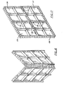
- the arrangement of mold form elements having angled flanges is shown in Figure 17.
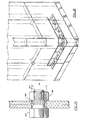
- Four mold elements 135, 136, 137 and 138 are held together by nuts and bolts 139 typically of the type shown in Figure 25.
- mold form elements may be of any desired shape. Particular shaped forms may be used for corners or for the junction of the walls and the roof or for construction of stair cases and the like. Suitable mold form elements for the production of corners and the manner of use are shown in Figs. 15 and 16. The general principle of construction and assembly of such forms will, however, be the same as has been described thereto.
- the two sets of mold elements constituting the opposite faces of a wall have a number of holes therein in the various mold elements, as shown for example, as shown as hole 130 in Figure 9.
- spacing ties are inserted to ensure that proper separation between the mold form elements for each of the faces of the wall is maintained during the pouring of the concrete. It is often convenient to apply a little grease or oil to the spacer tie before pulling it into position.
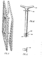
- a typical spacing tie is shown in Figure 12 wherein the taper of the tie is somewhat exaggerated for the convenience of the viewer.
- a nut suitable for use with the ties is shown in Figure 14. It will be noted that the spacing tie is tapered for ease of removal from the concrete after it has been poured into the mold shape formed by the oppositely facing assemblies of mold form elements.
- the correct spacing of the assemblies is assure by the guard 140 and the positions of the thread 141 which determines the final position which the nut 142 may adopt when tightened or to the spacing tie.
- the spacing tie is provided with a handle 143 for ease of tightening.
- the nut 142 is provided with a flange 144 which can "catch" on the strengthening 129 of the mold form elements. This then enable the spacing tie and nut to be tightened by a single workman on the "handle" side of the wall assemblies without the need for an additional workman to hold the nut while the spacing tie is being screwed into it.
- a typical arrangement showing the use of a spacer ties is shown in Fig. 11 and Fig. 14 shows a cross section of the vicinity of a space tie through the mold elements after concrete has been poured.
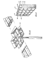
- Assembly of mold form elements for the roof of a single story building or the ceiling of the first floor and flooring for the second floor of a multi story building is effected in substantially the same way as the assembly of forms for the walls. In this case, however, the "top" can be left open unless the roofing is on a slant. In the case, where an assembly of mold forms is used only for the underside of the roof, the top side of the concrete for the roof may be smoothed manually in the same manner as was done for the initial floor laid on the ground.
- the arrangement I have devised particularly facilitates the disassembly of most of the elements for the roof assembly while leaving certain elements in position where they may be supplied by struts. This enables one to disassemble the roof mold assembly before the concrete of the roof has fully set since the remains elements supported by the struts provide sufficient support for the particularly set room concrete.
- They key to my inventive assembly for a roof mold is the use of a mold piece having angled flanges. The flanges are directed "inwardly".
- the mold form assembly element of this design need not be any larger than is needed to be mounted on the top of a support strut and provide local support for the roof. Use of an element of this type enable adjacent elements to be removed easily when the time comes to disassemble the roof mold while leaving the element itself in position mounted on a supporting strut.
- abutting element 146 are elements 151, 152, 153 and 154 each of which has two "outwardly” angled flanges on the sides which abut element 146 but has a flange perpendicular to the base plate on its other two sides.
- Abutting elements 147 and 152 is element 153
- abutting elements 149 and 153 is element 158
- abutting elements 149 and 154 is element 155 and abutting element 151 and 147 is element 156.
- Each of elements 153, 156, 155 and 156 has only a single flange which is angled (in each case "outwardly") the remaining flanges being perpendicular to the base plate.
- brace Most conveniently mold form elements for the under face of the roof can be raised to roof level using a hoister of the type shown in Figure 22. If additional bracing for the walls during the pouring of the concrete is required, as is often the case when no roof is present, this can be provided by the use of a brace.
- the assembly of mold elements may be substantially disassembled. Mold form elements for the underside of the roof are removed with the exeption of those mold elements which are supported by a strut.
- the angled flanges of the mold elements enable one to effect a partial sliding of the flanges over each other to break the seal of the mold with the concrete rather than requiring a direct pull perpendicular to the face of an element and thus substantially simplified the removal of the first pieces.
- Such movement of the pieces is achieved by use of hand operated levers. once some of the pieces having such angled flanges have been removed, removal of the remaining elements is easier.
- the spacer ties which have kept the forms for the two faces of the wall properly spaced are removed.
- the L-shaped pieces are then knocked or levered out of their position beneath the mold assembly thereby allowing the force of gravity to encourage the mold elements to drop and break their seal with the concrete.
- the mold is then disassembled starting with those mold pieces which have angled flanges.
- the mold may then be reassembled at the next site where the prior preparations have already taken place.
- the process may then be repeated in similar manner until the series of buildings is terminated.
- the elements are the surfaces which make contact with the concrete or other material used. They are totally metallic and comprise a smooth contact surface surrounded by metal flanges 131, and can be a metal sheet reinforced by a strengthening frame 129.
- This frame placed in its posterior part, allows the contact surface to endure the pressures of the product poured in the mold, as well as the overlying joints with other panels.
- the frame can best be described as reinforcement ribs.
- the panels can be classified in the following groups:
- the present invention have a series of characteristics that give a great functionality and great universality in use; such characteristics are:
- the mentioned perforations are a uniform distance face taking into consideration the thickness of the contact surface this, as shown on Figure 10, where it is observed that the distance a 2 is equal to the sum of the distance a l and the thickness of the frontal surface.
- metal strips having holes aligned with the holes of the flanges may be placed above the tops of the flanges and a further assembly of mold elements placed on top thereof.
- the metal strip when bolted to the flanges serves to hold the elements in the correct position at right angles to each other.
- Special elements are available for the assembly of molds for use where concrete or like material is to be poured for a structure which is not of regular shape.
- the length "1" existing between the centre of the perforations must correspond to the width of the perimetric platen, plus the thickness of the contact surface, this is a3.
- one end of such a corner piece may be set at an angle to the perpendicular.
- the end pieces 133 have circular perforations 128 with diameters identical to the ones existing in the perforated flanges keeping also the same relations of length a l , e, 1 1 and 1 2 , though not necessarily a 2 width.
- cornerings may be joined with any type of element already described, for example, as shown in Figure 15.
- Exterior cornering parts as shown in Figure 16 can be joined tightly with other elements.
- Three types of pieces are specifically designed to facilitate disassembly of the mold.
- the retrieval panels are used in complementary pairs and in replacement of the standardized elements for example as shown in Figure 17.
- the retrieval panels with flanges in non-right angle in two laterals are used to replace standardized panels in the molding for the roofs, since they allow an easy retrieval as well as the propping to support the weight of the product poured for a certain period of time after the panels of the mold have been removed.
- the perforated flanges 18 similar to the one existing in the retrieval panels of wedge type, generally have circular perforations 128, and comply the relations in corresponding dimensions with the standardized panels.
- the element of cross type is used preferably for the conformation of molds for the roofs and joint in all its sides by retrieval panels of wedge type, serves as a support for the support beams. When the roof is removed, it is the last panel to be recovered and its placing divides the surrounding panels in four areas of mold removal.
- the retrieval panels are strategically placed in the roofs, in such manner that allow the commencement of the panel removal in a easy way once the concrete or similar has set in several places as well as guarantee an exact support once the panels are removed, to support the structure of the roof and avoid that it does not suffer deformations by lack of curing.
- L-shaped pieces as shown in Figure 26 consist of a metallic surface of irregular thickness foled in an angle shape.
- thickness "C” acts as a surface of contact with the concrete or product to be poured. They generally have circular perforations in their length, similar to the ones existing in the perforated flanges of the standardized elements.
- Retrieval panels of the general type can also be used to conform corners. Their shape is of a platen, cut in a square form. Its thickness, not uniform, is less in two frontal faces.
- Both the screw 185 and the bolt 186 have in their head ends the shape of truncated cones, 187, 188 and when screwing, these cones are encountered.
- the screws pass through the circular or elliptic perforations of the panels with more than enough tolerance, and when screwing the panels, these slide through the cones of the screw and bolt, thus, forcing them to join exactly.
- Figures 12 and 13 show a separating tie and a nut for use therewith.
- the tie consists of a metallic tapered bar that has a threading 141 in the thinnest and in the thickest end has a guard 140.
- the separating tie is the element with which the inventor joins the faced panels, passing it through the circular perforations previously described in the box referred to panels.
- the system offered by the inventor widely reduces this task since the conic gap keeper is introduced through the perforations existing in the metal sheets and the nut is placed on its end.
- the length of the separator tie is the determinant of the thickness of the wall, adding to it the width "a3" of the two panels and the length "r" of the thread. (screw)
- the conic gap keeper After performing the pouring of concrete, the conic gap keeper is recuperated by making it turn slightly; its taper allows easy removal.
- the disposition of a tie after pouring of concrete and before disassembly of the mold is shown in Figure 14.
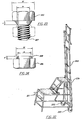
- the metallic bars are known to provide support to the structures or panels for the molds, but the strut of the present invention is provided with a thread over a cylindrical metal bar that confers the advantage of handling with milimetrical accuracy to obtain lengths with no error. In addition, it allows the mobility even if supporting high loads, since the rotation of the threaded axle is produced over a metallic screw fixed to the tube.
- the bar is basically composed of two tubular bodies, placed in a telescopic manner and with regular perforations and coincedental, by which it is possible to penetrate a metallic pin that holds the two tubes in a fixed relationship.
- a metallic threaded screw fixed on its interior part to which another cilindric element is also threaded and is provided of two or more arms to facilitate its manual rotation.
- a base Joined to the tube of greater thickness is a base, the linkage being by means of an axle.
- a reinforcement bar which is a metallic profile of "U" shape provided of circular and regular perforations on both lateral ends as well as in the centre.
- the mentioned lateral perforations coincide in shape and dimensions with the ones pointed in our box dedicated to the standardized panels, to the perimetric platens, maintaining the same relation in diameters, as well as distances between centres and borders of metal sheet.
- the referred reinforcement bar is used as an additional element of support in situations of critical load, as much in panels as in roofs.
- the reinforcement bar is the part that directly receives the effort transmitted by the spacer ties since these pass through two of these profiles, placed contrarily joined to the panels of the mold.
- the reinforcement bar is also subject to be used as an element of alignment and support in overhanging roofs as well as for the reinforcement of groups of panels with the object of giving greater solidity and facilitate their handling with mechanical means.
- the inventor has developed the mentioned profile to obtain a perfect alignment of the wall molds in which the mold for pouring roofs is not incorporated.
- the profile is fixed to the superior perforations existing in the elements by means of screws, with which a perfect alignment is obtained.
- H oisters are for the placing of the panels that conform the mold of roofs, or the ones assigned to walls that due to their height the placing is difficult (for example, the walls of a two story housing).
- the hoister shown in Figure 22 equipped in its front part of two fixed wheels 220 as well as handles 221 in the posterior part, in order to be able to handle it by one single person as a handtruck.
- the frontal part incorporates a system of profiles 222 placed in a telescopic manner and a cable hoist 223 which is operable manually or by use of a molar.
- the hoist incorporates a system of lock to avoid sliding while in use.
- pivot system 224 of fastening of panels tilting with a superior turn of 90°, which allow the rising of panels in a vertical form and then be subject to adopt a horizontal or inclinated position.
- the hoister has reinforcements in the back part subject to be used as a ladder and as a work platform.
- This accessory is an adjustable mechanism used to fix and maintain the verticality of the molds of the walls, when these are poured without molds for the roof.
- the joint of the threaded axle and base platform are articulated in such a manner that allow the rotation of the threaded axle.
- Joined to a screwed bolt in the mentioned threaded axle is a metallic profile at which end is a platen with a circular perforation.
- the stabilizers by means of the perforated flanges, are joined to the panels of the mold, and driving the handle in a circular movement manner allows the placing of the mold of panel in any position desired.
- Figure 21 shows laminar profiles to hold the frames for doors, windows, etc. in the interior part of the mold.
- the framecovers are shaped so as to have an area 118 deformed from the plane of their exterior ends and have circular or elliptic perforations l19 in their exterior ends, complying the same specification that the panels of the mold to which they are joined.
- the divider has tubular element having an oblique cut in its middle section to facilitate the retrieval once the pouring is done. At ends are shaped profiles shaped to fit around door frame covers.
- the mentioned panel is formed by a metallic panel in "L" shape with platens perpendicularly joint in their ends and in each one of the internal angles. These platens have circular perforations that allow the union of the panels among each other. In order to be fixed to the foundation of the floor, the panels have circular perforations on one of its sides, and aligned to these platens with perforations.
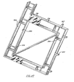
- the ground pattern that must be prepared individually for every project to be performed, consists in a tubular structure 204, 205 joined by metallic elements 206, which exactly reproduces the ends of the horizontal projection of a construction.
- each one of the lines of the end of vertical projection a tubular structure is placed and reproduced exactly, and at 1:1 scale, the mentioned production; each one of the sides are joined to the other by means of laminar platens placed regularly at a certain distance.
- hooks 207 that will serve to support the body of the pattern over the panels of the mold of the floor.
- the ground pattern eliminates the need of taking measures for the exact placing of the structure to be performed. In addition, allows that when performing marks and signals over the pattern, indicate exactly the location of any type of service (electricity, plumbing, etc.). Of course, it points out the perfect placing of the walls and the structure to be construed, since it reproduces exactly the horizontal projection of the walls.
Landscapes
- Engineering & Computer Science (AREA)
- Architecture (AREA)
- Mechanical Engineering (AREA)
- Civil Engineering (AREA)
- Structural Engineering (AREA)
- Forms Removed On Construction Sites Or Auxiliary Members Thereof (AREA)
- Ceramic Products (AREA)
- On-Site Construction Work That Accompanies The Preparation And Application Of Concrete (AREA)
Applications Claiming Priority (4)
| Application Number | Priority Date | Filing Date | Title |
|---|---|---|---|
| US48590183A | 1983-04-18 | 1983-04-18 | |
| US485901 | 1983-04-18 | ||
| US53750083A | 1983-09-30 | 1983-09-30 | |
| US537500 | 1983-09-30 |
Publications (2)
| Publication Number | Publication Date |
|---|---|
| EP0123264A2 true EP0123264A2 (fr) | 1984-10-31 |
| EP0123264A3 EP0123264A3 (fr) | 1986-10-22 |
Family
ID=27048509
Family Applications (1)
| Application Number | Title | Priority Date | Filing Date |
|---|---|---|---|
| EP84104368A Withdrawn EP0123264A3 (fr) | 1983-04-18 | 1984-04-17 | Système de bâtiment et ses composants |
Country Status (5)
| Country | Link |
|---|---|
| EP (1) | EP0123264A3 (fr) |
| AU (1) | AU2689584A (fr) |
| BR (1) | BR8401812A (fr) |
| ES (2) | ES8605068A1 (fr) |
| FR (2) | FR2544356B1 (fr) |
Cited By (18)
| Publication number | Priority date | Publication date | Assignee | Title |
|---|---|---|---|---|
| EP0399114A1 (fr) * | 1989-05-26 | 1990-11-28 | Hendrik Petrus Botes | Coffrage pour la construction de bâtiments |
| FR2659592A1 (fr) * | 1990-03-19 | 1991-09-20 | Hourdeaux Jacques | Moule modulaire pour bassin. |
| GR900100223A (en) * | 1990-03-26 | 1992-06-30 | Hristos Doukas | Construction moulds for buildings |
| AP332A (en) * | 1991-10-01 | 1994-04-21 | Hendrik Petrus Botes | Shuttering in building construction. |
| EP0679781A3 (fr) * | 1994-04-28 | 1996-02-21 | Yoshiyuki Hayakawa | Coffrage de béton, et tirant et raccord pour l'assemblage du coffrage. |
| ES2142222A1 (es) * | 1997-03-24 | 2000-04-01 | Comercializacion Integral De L | Sistema de construccion de estructuras de viviendas y similares. |
| WO2002020921A1 (fr) * | 2000-09-06 | 2002-03-14 | Trottmann Rene | Element de coffrage permettant de construire un batiment hemispherique et procede de coffrage lors de cette construction |
| ES2281212A1 (es) * | 2002-11-18 | 2007-09-16 | Sistemas Industrializados Barcons, S.L. | Perfeccionamientos en los sistemas de construccion de estructuras de hormigon armado u otro material mediante encofrados modulares e integrales de alta precision. |
| AU2002323707B2 (en) * | 2001-12-21 | 2007-10-25 | Peter Bilowol | Formwork Systems |
| WO2010082812A3 (fr) * | 2009-01-15 | 2010-11-04 | Universiti Teknologi Malaysia | Système de parois pour construction rapide |
| EP1711667B1 (fr) * | 2003-12-13 | 2013-01-23 | Djordje Vukajlovic | Module de coffrage pour produire notamment des murs economisant le beton |
| DE102014108180B3 (de) * | 2014-06-11 | 2015-08-20 | Fujitsu Technology Solutions Intellectual Property Gmbh | Schraube zum Verschrauben eines Trägerelements für eine Teleskopschiene an einen Träger eines Serverrackgehäuses sowie Anordnung |
| EA025899B1 (ru) * | 2014-06-03 | 2017-02-28 | Мурат Абенович Ахметов | Система модульной опалубки |
| EP3205790A4 (fr) * | 2014-10-09 | 2018-04-04 | Hui Linda Technology Co. Ltd. | Système assemblé de coffrage de bâtiment à retrait précoce, et son procédé de montage |
| CN108297253A (zh) * | 2018-01-24 | 2018-07-20 | 中国建筑第七工程局有限公司 | 异形预制楼层板模具 |
| CN113266147A (zh) * | 2021-05-31 | 2021-08-17 | 广州珠江建设发展有限公司 | 基于bim的异形柱工具式木模快速施工工艺 |
| WO2022051821A1 (fr) * | 2020-09-11 | 2022-03-17 | Mrv Engenharia E Participacoes Sa | Système et procédé de construction avec coffrages de béton moulés dans le bâtiment lui-même |
| EP4155482A1 (fr) * | 2021-09-22 | 2023-03-29 | Chien-Ho Wang | Appareil de coffrage de construction doté d'un élément de verrouillage |
Families Citing this family (5)
| Publication number | Priority date | Publication date | Assignee | Title |
|---|---|---|---|---|
| AU642121B3 (en) * | 1992-04-03 | 1993-10-07 | Tony Bebek | Formwork |
| ES2120298B1 (es) * | 1994-05-24 | 1999-04-01 | Pujol Barcons Salvador | Perfeccionamientos en los sistemas de encofrados modulares e integrales, de alta precision, para la construccion de estructuras de hormigon armado. |
| CA2124492C (fr) * | 1994-05-27 | 2005-12-06 | Vittorio De Zen | Systeme de construction a profiles creux perfores |
| AU659401B3 (en) * | 1995-01-04 | 1995-05-11 | Jason Bugg | Formwork locator |
| CN104652805A (zh) * | 2015-02-11 | 2015-05-27 | 郭榕来 | 一种加筋建筑模板 |
Family Cites Families (14)
| Publication number | Priority date | Publication date | Assignee | Title |
|---|---|---|---|---|
| DE380394C (de) * | 1923-09-07 | Robert Neumann Hofer | Verschalung zur Errichtung von Betonmauerwerk nach dem Gussverfahren | |
| DE706254C (de) * | 1937-12-07 | 1941-05-22 | Aeg | Anordnung auf Fahrzeugen, insbesondere Luftfahrzeugen, zur Bestimmung von Abstaenden mittels Schall |
| FR1016420A (fr) * | 1949-10-06 | 1952-11-12 | Procédé de compression de bétons par vibrations et moules ou coffrages métalliques pour la réalisation de ce procédé | |
| DE882303C (de) * | 1950-10-15 | 1953-07-06 | Arthur Schroeder | Stahlblechschalung |
| GB740691A (en) * | 1952-01-23 | 1955-11-16 | Formwork Patents Ltd | Improvements in or relating to shuttering for concrete and reinforced concrete structures |
| CH354922A (fr) * | 1958-05-27 | 1961-06-15 | Kwikform Ltd | Coffrage pour le moulage d'un matériau tel que du béton |
| CH347967A (fr) * | 1959-01-07 | 1960-07-31 | Kwikform Ltd | Coffrage pour le moulage d'un matériau tel que du béton |
| CH407517A (de) * | 1963-05-03 | 1966-02-15 | Zuest Hans | Schalungseinrichtung |
| AT246410B (de) * | 1964-02-14 | 1966-04-25 | Fritz Wagner Baugesellschaft M | Stützeinrichtung für Bauschalungen |
| CH444457A (de) * | 1965-07-28 | 1967-09-30 | J P Van Eesteren S Administrat | Verfahren für den industriellen Bau von Wohnungen |
| FR1454731A (fr) * | 1965-11-12 | 1966-02-11 | Cadre de coffrage pour murs en béton | |
| BE706254A (fr) * | 1967-11-08 | 1968-03-18 | ||
| CH544861A (de) * | 1972-04-28 | 1974-01-15 | G Landry Max | Elément de coffrage métallique pour construction en béton |
| PT70931B (fr) * | 1980-03-11 | 1981-07-01 | Helio Guiod De Castro | Systeme de constructions d'edifices |
-
1984
- 1984-04-16 FR FR8405973A patent/FR2544356B1/fr not_active Expired
- 1984-04-17 ES ES531697A patent/ES8605068A1/es not_active Expired
- 1984-04-17 BR BR8401812A patent/BR8401812A/pt unknown
- 1984-04-17 EP EP84104368A patent/EP0123264A3/fr not_active Withdrawn
- 1984-04-17 AU AU26895/84A patent/AU2689584A/en not_active Abandoned
- 1984-10-15 FR FR8415763A patent/FR2550571B1/fr not_active Expired
-
1985
- 1985-04-16 ES ES542315A patent/ES8700718A1/es not_active Expired
Cited By (23)
| Publication number | Priority date | Publication date | Assignee | Title |
|---|---|---|---|---|
| EP0399114A1 (fr) * | 1989-05-26 | 1990-11-28 | Hendrik Petrus Botes | Coffrage pour la construction de bâtiments |
| FR2659592A1 (fr) * | 1990-03-19 | 1991-09-20 | Hourdeaux Jacques | Moule modulaire pour bassin. |
| GR900100223A (en) * | 1990-03-26 | 1992-06-30 | Hristos Doukas | Construction moulds for buildings |
| AP332A (en) * | 1991-10-01 | 1994-04-21 | Hendrik Petrus Botes | Shuttering in building construction. |
| EP0679781A3 (fr) * | 1994-04-28 | 1996-02-21 | Yoshiyuki Hayakawa | Coffrage de béton, et tirant et raccord pour l'assemblage du coffrage. |
| US5632923A (en) * | 1994-04-28 | 1997-05-27 | Hayakawa; Yoshiyuki | Concrete molding form member |
| ES2142222A1 (es) * | 1997-03-24 | 2000-04-01 | Comercializacion Integral De L | Sistema de construccion de estructuras de viviendas y similares. |
| WO2002020921A1 (fr) * | 2000-09-06 | 2002-03-14 | Trottmann Rene | Element de coffrage permettant de construire un batiment hemispherique et procede de coffrage lors de cette construction |
| HRP20030159B1 (en) * | 2000-09-06 | 2010-07-31 | Trottmann Rene | Shuttering element for the construction of a hemispherical building and method of shuttering in construction thereof |
| AU2002323707B2 (en) * | 2001-12-21 | 2007-10-25 | Peter Bilowol | Formwork Systems |
| DE10353277A1 (de) * | 2002-11-18 | 2009-05-07 | Sistemas Industrializados Barcons S.L., Puerto de Santa Maria | Verbesserungen an Systemen zum Bauen von Bauwerken in bewehrtem Beton oder einem anderen Material mit Hilfe hochpräziser, integraler, modularer Verschalungen |
| ES2281212A1 (es) * | 2002-11-18 | 2007-09-16 | Sistemas Industrializados Barcons, S.L. | Perfeccionamientos en los sistemas de construccion de estructuras de hormigon armado u otro material mediante encofrados modulares e integrales de alta precision. |
| EP1711667B1 (fr) * | 2003-12-13 | 2013-01-23 | Djordje Vukajlovic | Module de coffrage pour produire notamment des murs economisant le beton |
| WO2010082812A3 (fr) * | 2009-01-15 | 2010-11-04 | Universiti Teknologi Malaysia | Système de parois pour construction rapide |
| EA025899B1 (ru) * | 2014-06-03 | 2017-02-28 | Мурат Абенович Ахметов | Система модульной опалубки |
| DE102014108180B3 (de) * | 2014-06-11 | 2015-08-20 | Fujitsu Technology Solutions Intellectual Property Gmbh | Schraube zum Verschrauben eines Trägerelements für eine Teleskopschiene an einen Träger eines Serverrackgehäuses sowie Anordnung |
| EP3205790A4 (fr) * | 2014-10-09 | 2018-04-04 | Hui Linda Technology Co. Ltd. | Système assemblé de coffrage de bâtiment à retrait précoce, et son procédé de montage |
| CN108297253A (zh) * | 2018-01-24 | 2018-07-20 | 中国建筑第七工程局有限公司 | 异形预制楼层板模具 |
| CN108297253B (zh) * | 2018-01-24 | 2024-03-19 | 中国建筑第七工程局有限公司 | 异形预制楼层板模具 |
| WO2022051821A1 (fr) * | 2020-09-11 | 2022-03-17 | Mrv Engenharia E Participacoes Sa | Système et procédé de construction avec coffrages de béton moulés dans le bâtiment lui-même |
| CN113266147A (zh) * | 2021-05-31 | 2021-08-17 | 广州珠江建设发展有限公司 | 基于bim的异形柱工具式木模快速施工工艺 |
| EP4155482A1 (fr) * | 2021-09-22 | 2023-03-29 | Chien-Ho Wang | Appareil de coffrage de construction doté d'un élément de verrouillage |
| US11976478B2 (en) | 2021-09-22 | 2024-05-07 | Chien-Ho WANG | Building formwork apparatus having locking member |
Also Published As
| Publication number | Publication date |
|---|---|
| FR2544356A1 (fr) | 1984-10-19 |
| EP0123264A3 (fr) | 1986-10-22 |
| ES531697A0 (es) | 1986-03-01 |
| FR2550571A1 (fr) | 1985-02-15 |
| ES8605068A1 (es) | 1986-03-01 |
| ES542315A0 (es) | 1986-10-16 |
| ES8700718A1 (es) | 1986-10-16 |
| AU2689584A (en) | 1984-10-25 |
| BR8401812A (pt) | 1984-11-27 |
| FR2544356B1 (fr) | 1987-07-17 |
| FR2550571B1 (fr) | 1987-07-17 |
Similar Documents
| Publication | Publication Date | Title |
|---|---|---|
| EP0123264A2 (fr) | Système de bâtiment et ses composants | |
| JP6728309B2 (ja) | モジュラービルディングユニット、並びに、これの建設及び搬送方法 | |
| US4211043A (en) | Precast concrete building module form | |
| US4372906A (en) | Method and apparatus for pre-casting steel reinforced concrete box-like modules | |
| US6044614A (en) | Sequential formwork system for concrete buildings | |
| CN111395754B (zh) | 支模支撑系统的实施方法 | |
| WO2002066757A1 (fr) | Panneau de construction porteur | |
| US4003541A (en) | Portable decking form | |
| EP0065793B1 (fr) | Armature pour bâtiments en béton armé | |
| US20090121373A1 (en) | Method and Apparatus for Construction | |
| CN212866842U (zh) | 一种框构式建筑脚手架 | |
| CN111236631B (zh) | 一种半圆形混凝土顶板建筑支护结构 | |
| JP2931761B2 (ja) | 外壁材取付用固定装置及び同固定装置を用いた中・高層建築物の積層工法 | |
| JP2019203375A (ja) | コンクリート一体形成型のドーム状建築物及びその建築方法 | |
| CN212336729U (zh) | 支模支撑系统 | |
| AU2005287894B2 (en) | Method and apparatus for construction | |
| CN113846791B (zh) | 一种基于角钢肋钢底板预制盒型钢混组合装配式屋盖体系 | |
| CN111364758A (zh) | 支模支撑系统 | |
| JP3029125U (ja) | 建築用型枠パネルの桁梁支承装置 | |
| JP2601752B2 (ja) | 曲面型わく | |
| JP2691554B2 (ja) | 柱のユニット型枠装置 | |
| JPH0235951Y2 (fr) | ||
| JPS6137426B2 (fr) | ||
| JPH07119522B2 (ja) | 型枠装置 | |
| JPS6092556A (ja) | 単一構成の成形建築方式及び装置 |
Legal Events
| Date | Code | Title | Description |
|---|---|---|---|
| PUAI | Public reference made under article 153(3) epc to a published international application that has entered the european phase |
Free format text: ORIGINAL CODE: 0009012 |
|
| AK | Designated contracting states |
Designated state(s): AT DE FR GB IT |
|
| PUAL | Search report despatched |
Free format text: ORIGINAL CODE: 0009013 |
|
| AK | Designated contracting states |
Kind code of ref document: A3 Designated state(s): AT DE FR GB IT |
|
| STAA | Information on the status of an ep patent application or granted ep patent |
Free format text: STATUS: THE APPLICATION IS DEEMED TO BE WITHDRAWN |
|
| 18D | Application deemed to be withdrawn |
Effective date: 19861031 |