EP0127082B1 - Steuerungsvorrichtung für ein stufenloses Kraftfahrzeugmotor-Getriebesystem - Google Patents
Steuerungsvorrichtung für ein stufenloses Kraftfahrzeugmotor-Getriebesystem Download PDFInfo
- Publication number
- EP0127082B1 EP0127082B1 EP84105645A EP84105645A EP0127082B1 EP 0127082 B1 EP0127082 B1 EP 0127082B1 EP 84105645 A EP84105645 A EP 84105645A EP 84105645 A EP84105645 A EP 84105645A EP 0127082 B1 EP0127082 B1 EP 0127082B1
- Authority
- EP
- European Patent Office
- Prior art keywords
- reduction ratio
- deviation
- continuously variable
- variable transmission
- control
- Prior art date
- Legal status (The legal status is an assumption and is not a legal conclusion. Google has not performed a legal analysis and makes no representation as to the accuracy of the status listed.)
- Expired
Links
- 230000005540 biological transmission Effects 0.000 title claims description 19
- 230000009467 reduction Effects 0.000 claims description 54
- 230000007246 mechanism Effects 0.000 claims description 8
- 230000004044 response Effects 0.000 claims description 7
- 238000009877 rendering Methods 0.000 claims 1
- 238000011217 control strategy Methods 0.000 description 4
- 238000010586 diagram Methods 0.000 description 4
- 239000000446 fuel Substances 0.000 description 4
- 238000000034 method Methods 0.000 description 4
- 230000008569 process Effects 0.000 description 3
- 230000004075 alteration Effects 0.000 description 2
- 230000008859 change Effects 0.000 description 2
- 230000001133 acceleration Effects 0.000 description 1
- 239000000470 constituent Substances 0.000 description 1
- 238000010276 construction Methods 0.000 description 1
- 230000003247 decreasing effect Effects 0.000 description 1
- 230000000881 depressing effect Effects 0.000 description 1
- 230000004069 differentiation Effects 0.000 description 1
- 230000006870 function Effects 0.000 description 1
Images






Classifications
-
- F—MECHANICAL ENGINEERING; LIGHTING; HEATING; WEAPONS; BLASTING
- F16—ENGINEERING ELEMENTS AND UNITS; GENERAL MEASURES FOR PRODUCING AND MAINTAINING EFFECTIVE FUNCTIONING OF MACHINES OR INSTALLATIONS; THERMAL INSULATION IN GENERAL
- F16H—GEARING
- F16H61/00—Control functions within control units of change-speed- or reversing-gearings for conveying rotary motion ; Control of exclusively fluid gearing, friction gearing, gearings with endless flexible members or other particular types of gearing
- F16H61/66—Control functions within control units of change-speed- or reversing-gearings for conveying rotary motion ; Control of exclusively fluid gearing, friction gearing, gearings with endless flexible members or other particular types of gearing specially adapted for continuously variable gearings
-
- B—PERFORMING OPERATIONS; TRANSPORTING
- B60—VEHICLES IN GENERAL
- B60W—CONJOINT CONTROL OF VEHICLE SUB-UNITS OF DIFFERENT TYPE OR DIFFERENT FUNCTION; CONTROL SYSTEMS SPECIALLY ADAPTED FOR HYBRID VEHICLES; ROAD VEHICLE DRIVE CONTROL SYSTEMS FOR PURPOSES NOT RELATED TO THE CONTROL OF A PARTICULAR SUB-UNIT
- B60W10/00—Conjoint control of vehicle sub-units of different type or different function
- B60W10/04—Conjoint control of vehicle sub-units of different type or different function including control of propulsion units
-
- B—PERFORMING OPERATIONS; TRANSPORTING
- B60—VEHICLES IN GENERAL
- B60W—CONJOINT CONTROL OF VEHICLE SUB-UNITS OF DIFFERENT TYPE OR DIFFERENT FUNCTION; CONTROL SYSTEMS SPECIALLY ADAPTED FOR HYBRID VEHICLES; ROAD VEHICLE DRIVE CONTROL SYSTEMS FOR PURPOSES NOT RELATED TO THE CONTROL OF A PARTICULAR SUB-UNIT
- B60W10/00—Conjoint control of vehicle sub-units of different type or different function
- B60W10/10—Conjoint control of vehicle sub-units of different type or different function including control of change-speed gearings
- B60W10/101—Infinitely variable gearings
-
- B—PERFORMING OPERATIONS; TRANSPORTING
- B60—VEHICLES IN GENERAL
- B60W—CONJOINT CONTROL OF VEHICLE SUB-UNITS OF DIFFERENT TYPE OR DIFFERENT FUNCTION; CONTROL SYSTEMS SPECIALLY ADAPTED FOR HYBRID VEHICLES; ROAD VEHICLE DRIVE CONTROL SYSTEMS FOR PURPOSES NOT RELATED TO THE CONTROL OF A PARTICULAR SUB-UNIT
- B60W30/00—Purposes of road vehicle drive control systems not related to the control of a particular sub-unit, e.g. of systems using conjoint control of vehicle sub-units
- B60W30/18—Propelling the vehicle
- B60W30/1819—Propulsion control with control means using analogue circuits, relays or mechanical links
-
- F—MECHANICAL ENGINEERING; LIGHTING; HEATING; WEAPONS; BLASTING
- F16—ENGINEERING ELEMENTS AND UNITS; GENERAL MEASURES FOR PRODUCING AND MAINTAINING EFFECTIVE FUNCTIONING OF MACHINES OR INSTALLATIONS; THERMAL INSULATION IN GENERAL
- F16H—GEARING
- F16H61/00—Control functions within control units of change-speed- or reversing-gearings for conveying rotary motion ; Control of exclusively fluid gearing, friction gearing, gearings with endless flexible members or other particular types of gearing
- F16H61/66—Control functions within control units of change-speed- or reversing-gearings for conveying rotary motion ; Control of exclusively fluid gearing, friction gearing, gearings with endless flexible members or other particular types of gearing specially adapted for continuously variable gearings
- F16H61/662—Control functions within control units of change-speed- or reversing-gearings for conveying rotary motion ; Control of exclusively fluid gearing, friction gearing, gearings with endless flexible members or other particular types of gearing specially adapted for continuously variable gearings with endless flexible members
- F16H61/66254—Control functions within control units of change-speed- or reversing-gearings for conveying rotary motion ; Control of exclusively fluid gearing, friction gearing, gearings with endless flexible members or other particular types of gearing specially adapted for continuously variable gearings with endless flexible members controlling of shifting being influenced by a signal derived from the engine and the main coupling
- F16H61/66259—Control functions within control units of change-speed- or reversing-gearings for conveying rotary motion ; Control of exclusively fluid gearing, friction gearing, gearings with endless flexible members or other particular types of gearing specially adapted for continuously variable gearings with endless flexible members controlling of shifting being influenced by a signal derived from the engine and the main coupling using electrical or electronical sensing or control means
Definitions
- the invention relates to a control device for vehicular engine continuously variable transmission system comprising the features as indicated in the precharacterizing part of claim 1.
- Such a vehicular engine continuously variable transmission system as disclosed in US-A-4 261 229, comprises a control means for controlling an actuator to perform a desired reduction ratio.
- the system is useful to detect an actual reduction ratio and to compare it with a desired reduction ratio. In response to the position of the actuator, decreasing or increasing of an alteration rate of speed ratio will be performed.
- EP-A-111 891 (prior art according to Art 54(3) EPC) describes a method of controlling a continuously variable transmission, wherein a shift actuator operates in a slower speed at upshifting than at downshifting. Different but constant shifting speeds are reached by using time constants for controlling the shift actuator.
- a deviation between a desired reduction ratio and an actual reduction ratio is computed.
- a proportional gain and a differential gain are set for computing a shifting speed.
- shifting speed also the deviation is considered.
- Such an alteration of shifting speed is achieved to have a good response of actuating means to obtain the desired reduction ratio.
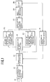
- a control strategy of a preferred embodiment is described.
- Fed to a block 10 are a plurality of signals 12 indicative of the operating state of a vehicular engine continuously variable transmission system, for example, a vehicle speed indicative signal and a throttle opening degree indicative signal.
- a desired reduction ratio is obtained by a computation based on the operating state indicative signals 12 and a signal is generated which is indicative of the desired reduction ratio to be fed to a block 14 where a deviation is computed.
- the desired reduction ratio determined in the block 10 is a reduction ratio which gives an engine speed with the least fuel consumption rate for a given vehicle speed and a given throttle opening degree, as will be later described.
- the deviation is computed between the desired reduction ratio signal fed thereto by the block 10 and an actual reduction ratio signal fed thereto by a later described block 16 where an actual reduction ratio in the continuously variable transmission (CVT) is detected.
- CVT continuously variable transmission
- a block 18 it is determined whether the deviation signal from the block 14 is positive or negative in order to judge which direction of shifting, i.e., a shifting in a direction toward a large reduction ratio or a shifting in a direction toward a small reduction ratio, should take place or is commanded.
- a predetermined control constant G1 is set in a block 20 which control constant G1 determines a speed at which the reduction ratio is shifted toward a large reduction ratio side.
- another predetermined control constant G2 is set in a block 22.
- the control constant G1 is larger than the control constant G2.
- a signal indicative of the control constant G1 or the control constant G2 is fed to a block 23 to which the deviation signal is also fed.
- a shift command signal is computed which commands the adjustment of an actual reduction ratio in a direction to reduce the deviation, that is, the adjustment toward the desired reduction ratio.
- the shift command signal is fed to the shift control mechanism 24 which varies the reduction ratio in the continuously variable transmission 26 based on this shift command signal. More specifically, a direction in which a shift control mechanism 24 is actuated and a speed at which the shift control mechanism 24 is actuated are determined, and the shift control mechanism 24 is actuated based on these information.
- the speed at which the shift control mechanism 24 is actuated is quick in downshifting control process where the control constant G1 is used as compared to the case where the shift control mechanism 24 is actuated in upshifting control process where the control constant G2 is used. It follows that downshifting speed is quicker than upshifting speed.
- control strategy described in connection with Fig. 1 may be carried out by a microcomputer containing a control program as shown by a flowchart in Fig. 2.
- signals indicative of operating state of the vehicle are detected (in a step 52).
- a determination is made whether a shift lever is in D range of L range (in a step 54). If it is in D range, a desired reduction ratio for D range is retrieved (in a step 56), while if it is in L range, a desired reduction ratio for L range is retrieved (in a step 58).
- An actual reduction ratio is detected (in a step 60) and a deviation between the desired reduction ratio and the actual reduction ratio is computed (in a step 62).
- a determination is made whether the deviation computed in the step 62 is positive or negative (in a step 64).
- the predetermined control constant G1 is set (in a step 66), while if the deviation is negative, the predetermined control constant G2 is set (in a step 68).
- a computation is effected on the control constant G1 or G2 set in the step 66 or 68 and the deviation computed in the step 62 so as to provide a shift command signal (in a step 70).
- the shift command signal is sent out (in a step 72).
- Fig. 3 shows engine performance curves including a minimum fuel consumption rate curve L. That is, if the engine operates on the curve L, the operation with the least fuel consumption rate is realized. As described before, the desired reduction ratio for the continuously variable transmission is determined so as to let the engine operate on this curve L. If this curve L is expressed in terms of a relationship between vehicle speed and engine speed, the relationship as illustrated in Fig. 4 is given.
- the present vehicular operating state is expressed in Fig. 4 by an operating point B which is expressed in terms of vehicle speed C, throttle opening degree 2/8 and reduction ratio b.
- the shifting speed in relatively slow, thus allowing a gradual shifting from the operating point A to the operating point B.
- a shift from the accelerating state to the normal operating state is made without causing the driver to feel uneasy.
- a vehicular engine continuously variable transmission system comprises an engine E having a throttle valve TV which opens in degrees in response to at least depression degree of an accelerator pedal AC.
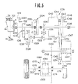
- the engine E is followed by a continuously variable transmission having a drive pulley 1006 and a driven pulley 1051 interconnected by a V-belt 1050 (see Fig. 5).
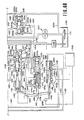
- Figs. 6A and 6B show a hydraulic control system including a start adjusting valve 1118 (see Fig. 6A) comprises a force motor 1224, a shift control mechanism 1112 including a shift control motor, i.e., a stepper motor, 1110 (see Fig. 6B), and an electronic control unit 1300. The construction of the electronic control unit 1300 is shown in Fig. 7.
- Figs. 5, 6A, 6B, and 7 hereof correspond to the reference numerals used in Figs. 1, 2A, 2B and 3 of the aforesaid co-pending application, respectively, except that, in the present application a timer 180 (see Fig. 7) illustrated in detail in Fig. 8 is employed.
- the timer 180 is provided to generate an interrupt signal 182.
- the timer 180 comprises a register 180A into which a frequency determined by a step 70B in a flowchart of a control program shown in Fig. 10 is stored, a timer 180B which counts reference clock pulses generated by a reference clock pulse generator 312, and a comparator 180C where the value stored in the register 180A and the value in the timer 180B are compared with each other. When these values become equal to each other, the comparator 180C resets the timer 180B and generates the aforementioned interrupt signal 182. This interrupt signal 182 is used to start or render into operation a stepper motor actuating program shown in Fig. 12 which will be later described.
- the timer 180 permits generation of interruption having any desired frequency.
- ON-OFF pattern of transistors A, B, C and D is shifted in the order of 1, 2, 3, 4, 1, 2, 3, 4...(see Fig. 9) for rotating the stepper motor 1110 in a direction indicated by an arrow X, whereas the pattern is shifted in the reverse order 4, 3, 2, 1, 4, 3, 2, 1...for rotating the stepper motor 1110 in the reverse direction indicated by an arrow Y.
- the speed at which the stepper motor 1110 is rotated can be varied by changing the speed at which the pattern is shifted.
- a throttle opening degree TH and a vehicle speed V are read.
- a step 60A is executed where an engine speed NE is read.
- an actual reduction ratio i is obtained by computing an equation KxNE/V, where: K is a constant determined by the final gear ratio and etc.
- the actual reduction ratio i is obtained by computing the equation
- the actual reduction ratio may be obtained by measuring the position of an axially movable conical disc of the drive pulley 1006 by means of a reduction ratio detector in the form of a potentiometer 16a as shown in Fig. 5 because the actual reduction ratio is determined by the position of the pulley.
- a step 62 is executed where a deviation e is obtained by subtracting the actual reduction ratio from the desired reduction ratio. Then, a determination is made whether the deviation e is positive or negative.
- the program proceeds to a step 66' where a proportional gain Kp is given a value Kp1 and a differential gain Kd is given a value Kd1, whereas if the deviation e is negative and a shifting toward a large reduction ratio or an upshifting is required, the program proceeds to a step 68' where the proportional gain Kp is given a value Kp2 and the differential gain Kd is given a value Kd2.
- the program proceeds to a step 70A where an actuating speed PPS is obtained by computing an equation representing a proportional and integral algorithm which will be described later referring to Fig. 11.
- the Kp1 and Kd1 are determined considering a transmitting function of the continuously variable transmission and takes values which provide the best response.
- the Kp2 and Kd2 take values smaller than Kp1 and Kd1, respectively, so as to provide the appropriate relatively slow response.
- the proportional and integral control is described.
- the actual reduction ratio is subtracted from the desired reduction ratio to provide the deviation e.
- the proportional gain Kp is multiplied with the deviation e at 220.
- the deviation e is differentiated and then the integral gain Kd is multiplied with the result of the differentiation to provide
- the proportional term Kpe is added to the integral term
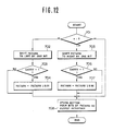
- Fig. 12 illustrates a flowchart of the stepper motor actuating program which program is started or rendered into operation by the interrupt signal 182 generated by the timer 180.
- a step 701 a determination is made whether the deviation e is positive or negative or zero. If it is negative, the program proceeds to a step 702 where PATARN (see Fig. 13) is shifted to the left by one bit.
- PATARN see Fig. 13
- a determination is made whether a carry signal appears or not in a step 703. If the carry signal appears, a digit "1" is written in the "0" bit of the PATARN. If no carry signal appears, the program proceeds to a step 708.
- step 701 If in the step 701, the deviation e is positive, the program proceeds to a step 705 where PATARN is shifted to the right by one bit and then to a step 706 where a determination is made whether a carry signal appears or not. If the carry signal appears, a digit "1" is written in the "7" bit location. If no carry signal appears, the program proceeds to the step 708. If, in the step 701, the deviation e is zero, the program proceeds to the step 708. In the step 708, the bottom four bits (see Fig. 13) of the PATARN are stored in a digital output device in the output interface 316.
Landscapes
- Engineering & Computer Science (AREA)
- Mechanical Engineering (AREA)
- Chemical & Material Sciences (AREA)
- Combustion & Propulsion (AREA)
- General Engineering & Computer Science (AREA)
- Transportation (AREA)
- Automation & Control Theory (AREA)
- Control Of Transmission Device (AREA)
- Transmissions By Endless Flexible Members (AREA)
Claims (2)
und daß vorgesehen sind
Applications Claiming Priority (2)
| Application Number | Priority Date | Filing Date | Title |
|---|---|---|---|
| JP92414/83 | 1983-05-27 | ||
| JP58092414A JPH073261B2 (ja) | 1983-05-27 | 1983-05-27 | 無段変速機の制御装置 |
Publications (3)
| Publication Number | Publication Date |
|---|---|
| EP0127082A2 EP0127082A2 (de) | 1984-12-05 |
| EP0127082A3 EP0127082A3 (en) | 1987-02-04 |
| EP0127082B1 true EP0127082B1 (de) | 1989-10-11 |
Family
ID=14053752
Family Applications (1)
| Application Number | Title | Priority Date | Filing Date |
|---|---|---|---|
| EP84105645A Expired EP0127082B1 (de) | 1983-05-27 | 1984-05-17 | Steuerungsvorrichtung für ein stufenloses Kraftfahrzeugmotor-Getriebesystem |
Country Status (4)
| Country | Link |
|---|---|
| US (1) | US4993284A (de) |
| EP (1) | EP0127082B1 (de) |
| JP (1) | JPH073261B2 (de) |
| DE (1) | DE3480078D1 (de) |
Families Citing this family (21)
| Publication number | Priority date | Publication date | Assignee | Title |
|---|---|---|---|---|
| JPS62149526A (ja) * | 1985-12-25 | 1987-07-03 | Fuji Heavy Ind Ltd | 無段変速機の制御装置 |
| JPH086797B2 (ja) * | 1986-07-15 | 1996-01-29 | 本田技研工業株式会社 | 車両用無段変速機の変速制御方法 |
| JPS6353129A (ja) * | 1986-08-20 | 1988-03-07 | Fuji Heavy Ind Ltd | 無段変速機の変速比制御装置 |
| DE3636463A1 (de) * | 1986-10-25 | 1988-05-05 | Daimler Benz Ag | Verfahren und vorrichtung zur steuerung des stufenlos veraenderlichen uebersetzungsverhaeltnisses eines kegelscheibenumschlingungsgetriebes in einem kraftfahrzeug |
| JP2613037B2 (ja) * | 1987-01-06 | 1997-05-21 | トヨタ自動車株式会社 | 車両用無段変速機の制御方法 |
| JPH07111221B2 (ja) * | 1987-10-20 | 1995-11-29 | 本田技研工業株式会社 | 車両用無段変速機の変速制御方法 |
| EP0321622A1 (de) * | 1987-12-23 | 1989-06-28 | Honda Giken Kogyo Kabushiki Kaisha | Steuereinrichtung für ein stufenlos regelbares Fahrzeuggetriebe |
| DE4441876C1 (de) * | 1994-11-24 | 1996-01-04 | Porsche Ag | Verfahren zur Bestimmung der Schaltzeit für einen Übersetzungswechsel in einem stufenlosen Getriebe |
| JP3460341B2 (ja) * | 1994-11-28 | 2003-10-27 | 日産自動車株式会社 | 摩擦車式無段変速機の変速制御装置 |
| JP3358435B2 (ja) * | 1996-04-12 | 2002-12-16 | 日産自動車株式会社 | 無段自動変速機の変速制御装置 |
| US5997431A (en) * | 1997-08-27 | 1999-12-07 | General Motors Corporation | Continuously variable transmission and control |
| EP0899480A3 (de) * | 1997-08-27 | 2001-03-28 | General Motors Corporation | Stufenloses Getriebe und Steuerung |
| US5924954A (en) * | 1997-08-27 | 1999-07-20 | General Motors Corporation | Continuously variable transmission and control |
| JP3319355B2 (ja) * | 1997-08-29 | 2002-08-26 | 日産自動車株式会社 | 無段変速機の変速比制御装置 |
| DE19908250A1 (de) * | 1999-02-25 | 2000-08-31 | Zahnradfabrik Friedrichshafen | Übersetzungsregelung eines stufenlosen Automatgetriebes |
| JP4799129B2 (ja) * | 2005-10-31 | 2011-10-26 | ジヤトコ株式会社 | 自動車用無段変速機の制御装置 |
| JP4849870B2 (ja) * | 2005-10-31 | 2012-01-11 | ジヤトコ株式会社 | 自動車用無段変速機の制御装置 |
| JP4842741B2 (ja) | 2006-09-01 | 2011-12-21 | ヤマハ発動機株式会社 | 鞍乗型車両 |
| JP2008232180A (ja) * | 2007-03-16 | 2008-10-02 | Toyota Motor Corp | 車両の変速制御装置 |
| JP5908205B2 (ja) * | 2010-11-30 | 2016-04-26 | 株式会社東芝 | 回転センサレス制御装置 |
| US8958961B2 (en) * | 2011-12-16 | 2015-02-17 | The Gates Corporation | Continuously variable transmission |
Citations (1)
| Publication number | Priority date | Publication date | Assignee | Title |
|---|---|---|---|---|
| EP0111891A2 (de) * | 1982-12-17 | 1984-06-27 | Nissan Motor Co., Ltd. | Verfahren zur Steuerung eines stufenlos veränderbaren Getriebes |
Family Cites Families (17)
| Publication number | Priority date | Publication date | Assignee | Title |
|---|---|---|---|---|
| US3412240A (en) * | 1963-02-21 | 1968-11-19 | Gen Precision Systems Inc | Linear interpolater |
| FR2188688A5 (de) * | 1972-06-02 | 1974-01-18 | Peugeot & Renault | |
| JPS5944536B2 (ja) * | 1977-08-10 | 1984-10-30 | アイシン精機株式会社 | 自動車の無段変速機の速度比自動制御装置 |
| JPS5944537B2 (ja) * | 1977-08-24 | 1984-10-30 | アイシン精機株式会社 | 自動車の無段変速機の速度比自動制御装置 |
| JPS5472360A (en) * | 1977-11-21 | 1979-06-09 | Aisin Seiki Co Ltd | Speed ratio control system or stageless speed change gear in vehicle |
| US4261229A (en) * | 1978-08-24 | 1981-04-14 | Aisin Seiki Kabushiki Kaisha | Automatic speed ratio control system for stepless transmission of automotive vehicles |
| US4387608A (en) * | 1979-09-12 | 1983-06-14 | Robert Bosch Gmbh | Electronic control for a stepless vehicle transmission using a control member response to dynamic pressure |
| JPS56138555A (en) * | 1980-03-29 | 1981-10-29 | Aisin Warner Ltd | Controlling device for stepless transmission used in vehicle |
| JPS5790450A (en) * | 1980-11-27 | 1982-06-05 | Nippon Denso Co Ltd | Automatic change gear control apparatus for vehicle |
| JPS57161346A (en) * | 1981-03-28 | 1982-10-04 | Nissan Motor Co Ltd | Speed change control method for v-belt stepless speed change gear |
| US4458318A (en) * | 1981-04-24 | 1984-07-03 | Borg-Warner Corporation | Control arrangement for a variable pulley transmission |
| EP0093413B1 (de) * | 1982-04-30 | 1988-02-03 | Nissan Motor Co., Ltd. | Vorrichtung zum Regeln des Leitungsdruckes in stufenlosen Getrieben |
| JPS58200842A (ja) * | 1982-05-14 | 1983-11-22 | Nissan Motor Co Ltd | Vベルト式無段変速機の制御装置 |
| US4458561A (en) * | 1982-05-21 | 1984-07-10 | Frank Andrew A | Control system and method for a power delivery system having a continuously variable ratio transmission |
| US4475416A (en) * | 1982-07-27 | 1984-10-09 | Borg-Warner Corporation | Continuously variable transmission down shift control |
| US4509125A (en) * | 1982-08-06 | 1985-04-02 | General Motors Corporation | Continuously variable transmission ratio control system |
| US4576265A (en) * | 1982-10-22 | 1986-03-18 | Nissan Motor Co., Ltd. | Control system for hydraulic automatic clutch |
-
1983
- 1983-05-27 JP JP58092414A patent/JPH073261B2/ja not_active Expired - Lifetime
-
1984
- 1984-05-16 US US06/610,794 patent/US4993284A/en not_active Expired - Lifetime
- 1984-05-17 EP EP84105645A patent/EP0127082B1/de not_active Expired
- 1984-05-17 DE DE8484105645T patent/DE3480078D1/de not_active Expired
Patent Citations (1)
| Publication number | Priority date | Publication date | Assignee | Title |
|---|---|---|---|---|
| EP0111891A2 (de) * | 1982-12-17 | 1984-06-27 | Nissan Motor Co., Ltd. | Verfahren zur Steuerung eines stufenlos veränderbaren Getriebes |
Also Published As
| Publication number | Publication date |
|---|---|
| JPS59219554A (ja) | 1984-12-10 |
| EP0127082A3 (en) | 1987-02-04 |
| US4993284A (en) | 1991-02-19 |
| DE3480078D1 (en) | 1989-11-16 |
| JPH073261B2 (ja) | 1995-01-18 |
| EP0127082A2 (de) | 1984-12-05 |
Similar Documents
| Publication | Publication Date | Title |
|---|---|---|
| US4993284A (en) | Control device for vehicular engine continuously variable transmission system | |
| EP0111891B1 (de) | Verfahren zur Steuerung eines stufenlos veränderbaren Getriebes | |
| JP2584765B2 (ja) | 自動変速機の変速制御装置 | |
| US4490790A (en) | Method and apparatus for selecting gears of an automatic transmission | |
| US4718012A (en) | Control system for drive train including continuously variable transmission | |
| EP0352551B1 (de) | Hochschaltlogik | |
| US5746679A (en) | Method and apparatus for controlling driving power of motor vehicle | |
| US5012418A (en) | Vehicle operating and speed regulating device | |
| US4913006A (en) | Automatic transmission control system for a vehicle having constant-speed cruising control system | |
| JP3491423B2 (ja) | 無段変速機の変速制御装置 | |
| EP0457585B1 (de) | System und Verfahren zur Regelung eines automatischen Getriebes | |
| US20040014558A1 (en) | Transmission control apparatus for an automatic transmission | |
| EP0890764B1 (de) | Schaltsteuersystem für automatisches Getriebe | |
| JPH08219244A (ja) | 無段変速機の制御装置 | |
| US7831365B2 (en) | Ratio control method for a continuously variable transmission | |
| US6098001A (en) | Apparatus for controlling a continuously variable transmission and method thereof | |
| GB2316139A (en) | A CVT with variable rates of shifting | |
| JPH09196156A (ja) | 無段変速機の変速制御装置 | |
| JP3659092B2 (ja) | 無段変速機の変速制御装置 | |
| JP3493904B2 (ja) | 無段変速機の変速制御装置 | |
| KR100254235B1 (ko) | 유압 응답을 고려한 변속 제어 장치 및 그 방법 | |
| JPH09203457A (ja) | 自動変速機の変速制御装置 | |
| JP3624639B2 (ja) | 自動変速機の変速制御装置 | |
| JPH0118920Y2 (de) | ||
| JP2001132827A (ja) | 無段変速機の変速制御装置 |
Legal Events
| Date | Code | Title | Description |
|---|---|---|---|
| PUAI | Public reference made under article 153(3) epc to a published international application that has entered the european phase |
Free format text: ORIGINAL CODE: 0009012 |
|
| 17P | Request for examination filed |
Effective date: 19840517 |
|
| AK | Designated contracting states |
Designated state(s): DE FR GB IT |
|
| RAP1 | Party data changed (applicant data changed or rights of an application transferred) |
Owner name: NISSAN MOTOR CO., LTD. |
|
| PUAL | Search report despatched |
Free format text: ORIGINAL CODE: 0009013 |
|
| AK | Designated contracting states |
Kind code of ref document: A3 Designated state(s): DE FR GB IT |
|
| 17Q | First examination report despatched |
Effective date: 19880120 |
|
| GRAA | (expected) grant |
Free format text: ORIGINAL CODE: 0009210 |
|
| AK | Designated contracting states |
Kind code of ref document: B1 Designated state(s): DE FR GB IT |
|
| PG25 | Lapsed in a contracting state [announced via postgrant information from national office to epo] |
Ref country code: IT Free format text: LAPSE BECAUSE OF FAILURE TO SUBMIT A TRANSLATION OF THE DESCRIPTION OR TO PAY THE FEE WITHIN THE PRESCRIBED TIME-LIMIT;WARNING: LAPSES OF ITALIAN PATENTS WITH EFFECTIVE DATE BEFORE 2007 MAY HAVE OCCURRED AT ANY TIME BEFORE 2007. THE CORRECT EFFECTIVE DATE MAY BE DIFFERENT FROM THE ONE RECORDED. Effective date: 19891011 Ref country code: FR Free format text: THE PATENT HAS BEEN ANNULLED BY A DECISION OF A NATIONAL AUTHORITY Effective date: 19891011 |
|
| REF | Corresponds to: |
Ref document number: 3480078 Country of ref document: DE Date of ref document: 19891116 |
|
| EN | Fr: translation not filed | ||
| PLBE | No opposition filed within time limit |
Free format text: ORIGINAL CODE: 0009261 |
|
| STAA | Information on the status of an ep patent application or granted ep patent |
Free format text: STATUS: NO OPPOSITION FILED WITHIN TIME LIMIT |
|
| 26N | No opposition filed | ||
| REG | Reference to a national code |
Ref country code: GB Ref legal event code: IF02 |
|
| PGFP | Annual fee paid to national office [announced via postgrant information from national office to epo] |
Ref country code: GB Payment date: 20030514 Year of fee payment: 20 |
|
| PGFP | Annual fee paid to national office [announced via postgrant information from national office to epo] |
Ref country code: DE Payment date: 20030529 Year of fee payment: 20 |
|
| PG25 | Lapsed in a contracting state [announced via postgrant information from national office to epo] |
Ref country code: GB Free format text: LAPSE BECAUSE OF EXPIRATION OF PROTECTION Effective date: 20040516 |
|
| REG | Reference to a national code |
Ref country code: GB Ref legal event code: PE20 |