EP0130213B1 - Aufzeichnungsmaterial zur optischen speicherung von informationen - Google Patents
Aufzeichnungsmaterial zur optischen speicherung von informationen Download PDFInfo
- Publication number
- EP0130213B1 EP0130213B1 EP84900465A EP84900465A EP0130213B1 EP 0130213 B1 EP0130213 B1 EP 0130213B1 EP 84900465 A EP84900465 A EP 84900465A EP 84900465 A EP84900465 A EP 84900465A EP 0130213 B1 EP0130213 B1 EP 0130213B1
- Authority
- EP
- European Patent Office
- Prior art keywords
- recording element
- recording
- substituted
- alkyl
- dye
- Prior art date
- Legal status (The legal status is an assumption and is not a legal conclusion. Google has not performed a legal analysis and makes no representation as to the accuracy of the status listed.)
- Expired
Links
- 230000003287 optical effect Effects 0.000 title claims abstract description 32
- 238000013500 data storage Methods 0.000 title description 7
- 239000000975 dye Substances 0.000 claims abstract description 108
- 125000000217 alkyl group Chemical group 0.000 claims abstract description 22
- 125000004432 carbon atom Chemical group C* 0.000 claims abstract description 22
- 125000003342 alkenyl group Chemical group 0.000 claims abstract description 11
- 125000004429 atom Chemical group 0.000 claims abstract description 11
- 125000005017 substituted alkenyl group Chemical group 0.000 claims abstract description 11
- 125000000623 heterocyclic group Chemical group 0.000 claims abstract description 10
- 125000004435 hydrogen atom Chemical group [H]* 0.000 claims abstract description 10
- 125000000547 substituted alkyl group Chemical group 0.000 claims abstract description 10
- 125000003710 aryl alkyl group Chemical group 0.000 claims abstract description 5
- 125000003118 aryl group Chemical group 0.000 claims abstract description 5
- 125000003545 alkoxy group Chemical group 0.000 claims abstract description 4
- 125000002877 alkyl aryl group Chemical group 0.000 claims abstract description 4
- DZVCFNFOPIZQKX-LTHRDKTGSA-M merocyanine Chemical compound [Na+].O=C1N(CCCC)C(=O)N(CCCC)C(=O)C1=C\C=C\C=C/1N(CCCS([O-])(=O)=O)C2=CC=CC=C2O\1 DZVCFNFOPIZQKX-LTHRDKTGSA-M 0.000 claims abstract description 4
- 230000002378 acidificating effect Effects 0.000 claims abstract description 3
- 125000002837 carbocyclic group Chemical group 0.000 claims abstract description 3
- 125000005415 substituted alkoxy group Chemical group 0.000 claims abstract description 3
- ANRHNWWPFJCPAZ-UHFFFAOYSA-M thionine Chemical compound [Cl-].C1=CC(N)=CC2=[S+]C3=CC(N)=CC=C3N=C21 ANRHNWWPFJCPAZ-UHFFFAOYSA-M 0.000 claims abstract 3
- 239000011230 binding agent Substances 0.000 claims description 53
- -1 thianaphtheno-7'-6' Chemical compound 0.000 claims description 38
- 239000000758 substrate Substances 0.000 claims description 32
- 239000000463 material Substances 0.000 claims description 16
- 229920003229 poly(methyl methacrylate) Polymers 0.000 claims description 12
- 239000004926 polymethyl methacrylate Substances 0.000 claims description 12
- 229920000728 polyester Polymers 0.000 claims description 11
- 229920000642 polymer Polymers 0.000 claims description 10
- JUJWROOIHBZHMG-UHFFFAOYSA-N Pyridine Chemical compound C1=CC=NC=C1 JUJWROOIHBZHMG-UHFFFAOYSA-N 0.000 claims description 8
- IOJUPLGTWVMSFF-UHFFFAOYSA-N benzothiazole Chemical compound C1=CC=C2SC=NC2=C1 IOJUPLGTWVMSFF-UHFFFAOYSA-N 0.000 claims description 8
- 125000001424 substituent group Chemical group 0.000 claims description 6
- 239000007789 gas Substances 0.000 claims description 5
- 230000005855 radiation Effects 0.000 claims description 5
- 239000004793 Polystyrene Substances 0.000 claims description 4
- 230000002708 enhancing effect Effects 0.000 claims description 4
- 229920002223 polystyrene Polymers 0.000 claims description 4
- AIGNCQCMONAWOL-UHFFFAOYSA-N 1,3-benzoselenazole Chemical compound C1=CC=C2[se]C=NC2=C1 AIGNCQCMONAWOL-UHFFFAOYSA-N 0.000 claims description 3
- BCMCBBGGLRIHSE-UHFFFAOYSA-N 1,3-benzoxazole Chemical compound C1=CC=C2OC=NC2=C1 BCMCBBGGLRIHSE-UHFFFAOYSA-N 0.000 claims description 3
- ZLTPDFXIESTBQG-UHFFFAOYSA-N isothiazole Chemical compound C=1C=NSC=1 ZLTPDFXIESTBQG-UHFFFAOYSA-N 0.000 claims description 3
- FUOSTELFLYZQCW-UHFFFAOYSA-N 1,2-oxazol-3-one Chemical compound OC=1C=CON=1 FUOSTELFLYZQCW-UHFFFAOYSA-N 0.000 claims description 2
- ODIRBFFBCSTPTO-UHFFFAOYSA-N 1,3-selenazole Chemical compound C1=C[se]C=N1 ODIRBFFBCSTPTO-UHFFFAOYSA-N 0.000 claims description 2
- CZWWCTHQXBMHDA-UHFFFAOYSA-N 3h-1,3-thiazol-2-one Chemical compound OC1=NC=CS1 CZWWCTHQXBMHDA-UHFFFAOYSA-N 0.000 claims description 2
- OFOBLEOULBTSOW-UHFFFAOYSA-L Malonate Chemical compound [O-]C(=O)CC([O-])=O OFOBLEOULBTSOW-UHFFFAOYSA-L 0.000 claims description 2
- PCKPVGOLPKLUHR-UHFFFAOYSA-N OH-Indolxyl Natural products C1=CC=C2C(O)=CNC2=C1 PCKPVGOLPKLUHR-UHFFFAOYSA-N 0.000 claims description 2
- FZWLAAWBMGSTSO-UHFFFAOYSA-N Thiazole Chemical compound C1=CSC=N1 FZWLAAWBMGSTSO-UHFFFAOYSA-N 0.000 claims description 2
- HNYOPLTXPVRDBG-UHFFFAOYSA-N barbituric acid Chemical compound O=C1CC(=O)NC(=O)N1 HNYOPLTXPVRDBG-UHFFFAOYSA-N 0.000 claims description 2
- AMTXUWGBSGZXCJ-UHFFFAOYSA-N benzo[e][1,3]benzoselenazole Chemical compound C1=CC=C2C(N=C[se]3)=C3C=CC2=C1 AMTXUWGBSGZXCJ-UHFFFAOYSA-N 0.000 claims description 2
- KXNQKOAQSGJCQU-UHFFFAOYSA-N benzo[e][1,3]benzothiazole Chemical compound C1=CC=C2C(N=CS3)=C3C=CC2=C1 KXNQKOAQSGJCQU-UHFFFAOYSA-N 0.000 claims description 2
- WMUIZUWOEIQJEH-UHFFFAOYSA-N benzo[e][1,3]benzoxazole Chemical compound C1=CC=C2C(N=CO3)=C3C=CC2=C1 WMUIZUWOEIQJEH-UHFFFAOYSA-N 0.000 claims description 2
- 239000006185 dispersion Substances 0.000 claims description 2
- WJRBRSLFGCUECM-UHFFFAOYSA-N hydantoin Chemical compound O=C1CNC(=O)N1 WJRBRSLFGCUECM-UHFFFAOYSA-N 0.000 claims description 2
- JYGFTBXVXVMTGB-UHFFFAOYSA-N indolin-2-one Chemical compound C1=CC=C2NC(=O)CC2=C1 JYGFTBXVXVMTGB-UHFFFAOYSA-N 0.000 claims description 2
- LVWZTYCIRDMTEY-UHFFFAOYSA-N metamizole Chemical compound O=C1C(N(CS(O)(=O)=O)C)=C(C)N(C)N1C1=CC=CC=C1 LVWZTYCIRDMTEY-UHFFFAOYSA-N 0.000 claims description 2
- JEXVQSWXXUJEMA-UHFFFAOYSA-N pyrazol-3-one Chemical compound O=C1C=CN=N1 JEXVQSWXXUJEMA-UHFFFAOYSA-N 0.000 claims description 2
- DNTVKOMHCDKATN-UHFFFAOYSA-N pyrazolidine-3,5-dione Chemical compound O=C1CC(=O)NN1 DNTVKOMHCDKATN-UHFFFAOYSA-N 0.000 claims description 2
- CBDKQYKMCICBOF-UHFFFAOYSA-N thiazoline Chemical compound C1CN=CS1 CBDKQYKMCICBOF-UHFFFAOYSA-N 0.000 claims description 2
- HYZJCKYKOHLVJF-UHFFFAOYSA-N 1H-benzimidazole Chemical compound C1=CC=C2NC=NC2=C1 HYZJCKYKOHLVJF-UHFFFAOYSA-N 0.000 claims 1
- WFFZGYRTVIPBFN-UHFFFAOYSA-N 3h-indene-1,2-dione Chemical compound C1=CC=C2C(=O)C(=O)CC2=C1 WFFZGYRTVIPBFN-UHFFFAOYSA-N 0.000 claims 1
- 125000002373 5 membered heterocyclic group Chemical group 0.000 claims 1
- 125000004070 6 membered heterocyclic group Chemical group 0.000 claims 1
- ZCQWOFVYLHDMMC-UHFFFAOYSA-N Oxazole Chemical compound C1=COC=N1 ZCQWOFVYLHDMMC-UHFFFAOYSA-N 0.000 claims 1
- XYLMUPLGERFSHI-UHFFFAOYSA-N alpha-Methylstyrene Chemical compound CC(=C)C1=CC=CC=C1 XYLMUPLGERFSHI-UHFFFAOYSA-N 0.000 claims 1
- 125000005429 oxyalkyl group Chemical group 0.000 claims 1
- 239000010410 layer Substances 0.000 description 57
- 238000010521 absorption reaction Methods 0.000 description 18
- 239000000203 mixture Substances 0.000 description 17
- 238000000034 method Methods 0.000 description 16
- LFQSCWFLJHTTHZ-UHFFFAOYSA-N Ethanol Chemical compound CCO LFQSCWFLJHTTHZ-UHFFFAOYSA-N 0.000 description 15
- 238000000576 coating method Methods 0.000 description 15
- 238000002679 ablation Methods 0.000 description 14
- 239000002904 solvent Substances 0.000 description 14
- HEDRZPFGACZZDS-UHFFFAOYSA-N Chloroform Chemical compound ClC(Cl)Cl HEDRZPFGACZZDS-UHFFFAOYSA-N 0.000 description 12
- 239000011248 coating agent Substances 0.000 description 10
- 230000008569 process Effects 0.000 description 9
- 230000035945 sensitivity Effects 0.000 description 9
- QGKMIGUHVLGJBR-UHFFFAOYSA-M (4z)-1-(3-methylbutyl)-4-[[1-(3-methylbutyl)quinolin-1-ium-4-yl]methylidene]quinoline;iodide Chemical class [I-].C12=CC=CC=C2N(CCC(C)C)C=CC1=CC1=CC=[N+](CCC(C)C)C2=CC=CC=C12 QGKMIGUHVLGJBR-UHFFFAOYSA-M 0.000 description 8
- 238000009472 formulation Methods 0.000 description 8
- 229960001701 chloroform Drugs 0.000 description 7
- 239000011241 protective layer Substances 0.000 description 7
- 230000015572 biosynthetic process Effects 0.000 description 6
- 238000002425 crystallisation Methods 0.000 description 6
- 230000008025 crystallization Effects 0.000 description 6
- 125000006850 spacer group Chemical group 0.000 description 6
- 230000000694 effects Effects 0.000 description 5
- 238000002844 melting Methods 0.000 description 5
- 230000008018 melting Effects 0.000 description 5
- 229910052751 metal Inorganic materials 0.000 description 5
- 239000002184 metal Substances 0.000 description 5
- KDYVCOSVYOSHOL-UHFFFAOYSA-N 7-methylquinoline Chemical compound C1=CC=NC2=CC(C)=CC=C21 KDYVCOSVYOSHOL-UHFFFAOYSA-N 0.000 description 4
- JRLTTZUODKEYDH-UHFFFAOYSA-N 8-methylquinoline Chemical compound C1=CN=C2C(C)=CC=CC2=C1 JRLTTZUODKEYDH-UHFFFAOYSA-N 0.000 description 4
- SMWDFEZZVXVKRB-UHFFFAOYSA-N Quinoline Chemical compound N1=CC=CC2=CC=CC=C21 SMWDFEZZVXVKRB-UHFFFAOYSA-N 0.000 description 4
- 150000001875 compounds Chemical class 0.000 description 4
- 229920001577 copolymer Polymers 0.000 description 4
- AWJUIBRHMBBTKR-UHFFFAOYSA-N isoquinoline Chemical compound C1=NC=CC2=CC=CC=C21 AWJUIBRHMBBTKR-UHFFFAOYSA-N 0.000 description 4
- 229910052709 silver Inorganic materials 0.000 description 4
- 239000004332 silver Substances 0.000 description 4
- 238000001228 spectrum Methods 0.000 description 4
- UHOVQNZJYSORNB-UHFFFAOYSA-N Benzene Chemical group C1=CC=CC=C1 UHOVQNZJYSORNB-UHFFFAOYSA-N 0.000 description 3
- YMWUJEATGCHHMB-UHFFFAOYSA-N Dichloromethane Chemical compound ClCCl YMWUJEATGCHHMB-UHFFFAOYSA-N 0.000 description 3
- 230000008901 benefit Effects 0.000 description 3
- 230000008033 biological extinction Effects 0.000 description 3
- 230000008859 change Effects 0.000 description 3
- 238000010276 construction Methods 0.000 description 3
- BGTOWKSIORTVQH-UHFFFAOYSA-N cyclopentanone Chemical class O=C1CCCC1 BGTOWKSIORTVQH-UHFFFAOYSA-N 0.000 description 3
- 239000000428 dust Substances 0.000 description 3
- 150000002148 esters Chemical class 0.000 description 3
- 230000001965 increasing effect Effects 0.000 description 3
- 229910052757 nitrogen Inorganic materials 0.000 description 3
- 239000002245 particle Substances 0.000 description 3
- 239000004417 polycarbonate Substances 0.000 description 3
- 229920000515 polycarbonate Polymers 0.000 description 3
- 238000002310 reflectometry Methods 0.000 description 3
- 230000003595 spectral effect Effects 0.000 description 3
- 238000004528 spin coating Methods 0.000 description 3
- 239000000126 substance Substances 0.000 description 3
- 229910052714 tellurium Inorganic materials 0.000 description 3
- PORWMNRCUJJQNO-UHFFFAOYSA-N tellurium atom Chemical compound [Te] PORWMNRCUJJQNO-UHFFFAOYSA-N 0.000 description 3
- 238000009834 vaporization Methods 0.000 description 3
- 230000008016 vaporization Effects 0.000 description 3
- ITQTTZVARXURQS-UHFFFAOYSA-N 3-methylpyridine Chemical compound CC1=CC=CN=C1 ITQTTZVARXURQS-UHFFFAOYSA-N 0.000 description 2
- DTBDAFLSBDGPEA-UHFFFAOYSA-N 3-methylquinoline Chemical compound C1=CC=CC2=CC(C)=CN=C21 DTBDAFLSBDGPEA-UHFFFAOYSA-N 0.000 description 2
- QMHIMXFNBOYPND-UHFFFAOYSA-N 4-methylthiazole Chemical compound CC1=CSC=N1 QMHIMXFNBOYPND-UHFFFAOYSA-N 0.000 description 2
- VWMQXAYLHOSRKA-UHFFFAOYSA-N 5-chloro-1,3-benzoxazole Chemical compound ClC1=CC=C2OC=NC2=C1 VWMQXAYLHOSRKA-UHFFFAOYSA-N 0.000 description 2
- LMYVCXSKCQSIEQ-UHFFFAOYSA-N 5-methylquinoline Chemical compound C1=CC=C2C(C)=CC=CC2=N1 LMYVCXSKCQSIEQ-UHFFFAOYSA-N 0.000 description 2
- ZLLOWHFKKIOINR-UHFFFAOYSA-N 5-phenyl-1,3-thiazole Chemical compound S1C=NC=C1C1=CC=CC=C1 ZLLOWHFKKIOINR-UHFFFAOYSA-N 0.000 description 2
- HFDLDPJYCIEXJP-UHFFFAOYSA-N 6-methoxyquinoline Chemical compound N1=CC=CC2=CC(OC)=CC=C21 HFDLDPJYCIEXJP-UHFFFAOYSA-N 0.000 description 2
- IJGRMHOSHXDMSA-UHFFFAOYSA-N Atomic nitrogen Chemical compound N#N IJGRMHOSHXDMSA-UHFFFAOYSA-N 0.000 description 2
- PXHVJJICTQNCMI-UHFFFAOYSA-N Nickel Chemical compound [Ni] PXHVJJICTQNCMI-UHFFFAOYSA-N 0.000 description 2
- KBAYQFWFCOOCIC-GNVSMLMZSA-N [(1s,4ar,4bs,7s,8ar,10ar)-1,4a-dimethyl-7-propan-2-yl-2,3,4,4b,5,6,7,8,8a,9,10,10a-dodecahydrophenanthren-1-yl]methanol Chemical compound OC[C@@]1(C)CCC[C@]2(C)[C@H]3CC[C@H](C(C)C)C[C@H]3CC[C@H]21 KBAYQFWFCOOCIC-GNVSMLMZSA-N 0.000 description 2
- 125000001931 aliphatic group Chemical group 0.000 description 2
- 125000004183 alkoxy alkyl group Chemical group 0.000 description 2
- 229910052799 carbon Inorganic materials 0.000 description 2
- 239000008199 coating composition Substances 0.000 description 2
- 238000009833 condensation Methods 0.000 description 2
- 230000005494 condensation Effects 0.000 description 2
- 125000004122 cyclic group Chemical group 0.000 description 2
- JHIVVAPYMSGYDF-UHFFFAOYSA-N cyclohexanone Chemical compound O=C1CCCCC1 JHIVVAPYMSGYDF-UHFFFAOYSA-N 0.000 description 2
- BADXJIPKFRBFOT-UHFFFAOYSA-N dimedone Chemical compound CC1(C)CC(=O)CC(=O)C1 BADXJIPKFRBFOT-UHFFFAOYSA-N 0.000 description 2
- 238000002474 experimental method Methods 0.000 description 2
- 239000011521 glass Substances 0.000 description 2
- 239000000543 intermediate Substances 0.000 description 2
- 238000004519 manufacturing process Methods 0.000 description 2
- 150000002739 metals Chemical class 0.000 description 2
- 239000013081 microcrystal Substances 0.000 description 2
- 239000000178 monomer Substances 0.000 description 2
- 150000002894 organic compounds Chemical class 0.000 description 2
- 239000003960 organic solvent Substances 0.000 description 2
- 229920000058 polyacrylate Polymers 0.000 description 2
- 229920002689 polyvinyl acetate Polymers 0.000 description 2
- 239000011118 polyvinyl acetate Substances 0.000 description 2
- 229920000915 polyvinyl chloride Polymers 0.000 description 2
- 238000002360 preparation method Methods 0.000 description 2
- UMJSCPRVCHMLSP-UHFFFAOYSA-N pyridine Natural products COC1=CC=CN=C1 UMJSCPRVCHMLSP-UHFFFAOYSA-N 0.000 description 2
- 125000006413 ring segment Chemical group 0.000 description 2
- 229910052711 selenium Inorganic materials 0.000 description 2
- 239000007787 solid Substances 0.000 description 2
- 230000003068 static effect Effects 0.000 description 2
- 238000006467 substitution reaction Methods 0.000 description 2
- 229910052717 sulfur Inorganic materials 0.000 description 2
- DNIAPMSPPWPWGF-GSVOUGTGSA-N (R)-(-)-Propylene glycol Chemical compound C[C@@H](O)CO DNIAPMSPPWPWGF-GSVOUGTGSA-N 0.000 description 1
- UUJOCRCAIOAPFK-UHFFFAOYSA-N 1,3-benzoselenazol-5-ol Chemical compound OC1=CC=C2[se]C=NC2=C1 UUJOCRCAIOAPFK-UHFFFAOYSA-N 0.000 description 1
- BREUOIWLJRZAFF-UHFFFAOYSA-N 1,3-benzothiazol-5-ol Chemical compound OC1=CC=C2SC=NC2=C1 BREUOIWLJRZAFF-UHFFFAOYSA-N 0.000 description 1
- ORIIXCOYEOIFSN-UHFFFAOYSA-N 1,3-benzothiazol-6-ol Chemical compound OC1=CC=C2N=CSC2=C1 ORIIXCOYEOIFSN-UHFFFAOYSA-N 0.000 description 1
- UPPYOQWUJKAFSG-UHFFFAOYSA-N 1,3-benzoxazol-5-ol Chemical compound OC1=CC=C2OC=NC2=C1 UPPYOQWUJKAFSG-UHFFFAOYSA-N 0.000 description 1
- SAHAKBXWZLDNAA-UHFFFAOYSA-N 1,3-benzoxazol-6-ol Chemical compound OC1=CC=C2N=COC2=C1 SAHAKBXWZLDNAA-UHFFFAOYSA-N 0.000 description 1
- CYHVDCMBRUBZSS-UHFFFAOYSA-N 1,3-diethyl-2h-benzimidazole Chemical compound C1=CC=C2N(CC)CN(CC)C2=C1 CYHVDCMBRUBZSS-UHFFFAOYSA-N 0.000 description 1
- UHKAJLSKXBADFT-UHFFFAOYSA-N 1,3-indandione Chemical compound C1=CC=C2C(=O)CC(=O)C2=C1 UHKAJLSKXBADFT-UHFFFAOYSA-N 0.000 description 1
- ZOBPZXTWZATXDG-UHFFFAOYSA-N 1,3-thiazolidine-2,4-dione Chemical compound O=C1CSC(=O)N1 ZOBPZXTWZATXDG-UHFFFAOYSA-N 0.000 description 1
- HOUFOJVBRDZQAX-UHFFFAOYSA-N 1-ethyl-3-phenyl-2h-benzimidazole Chemical compound C12=CC=CC=C2N(CC)CN1C1=CC=CC=C1 HOUFOJVBRDZQAX-UHFFFAOYSA-N 0.000 description 1
- QRINVLDPXAXANH-UHFFFAOYSA-N 2,3,3a,4-tetrahydro-1,3-benzoselenazole Chemical compound C1C=CC=C2[Se]CNC21 QRINVLDPXAXANH-UHFFFAOYSA-N 0.000 description 1
- NKSZCPBUWGZONP-UHFFFAOYSA-N 3,4-dihydroisoquinoline Chemical compound C1=CC=C2C=NCCC2=C1 NKSZCPBUWGZONP-UHFFFAOYSA-N 0.000 description 1
- AOKRXIIIYJGNNU-UHFFFAOYSA-N 3-methylcyclopentan-1-one Chemical compound CC1CCC(=O)C1 AOKRXIIIYJGNNU-UHFFFAOYSA-N 0.000 description 1
- MFBXYJLOYZMFIN-UHFFFAOYSA-N 3-phenylcyclopentan-1-one Chemical compound C1C(=O)CCC1C1=CC=CC=C1 MFBXYJLOYZMFIN-UHFFFAOYSA-N 0.000 description 1
- YVORRVFKHZLJGZ-UHFFFAOYSA-N 4,5-Dimethyloxazole Chemical compound CC=1N=COC=1C YVORRVFKHZLJGZ-UHFFFAOYSA-N 0.000 description 1
- UWSONZCNXUSTKW-UHFFFAOYSA-N 4,5-Dimethylthiazole Chemical compound CC=1N=CSC=1C UWSONZCNXUSTKW-UHFFFAOYSA-N 0.000 description 1
- NPSUJLPTWYJQCD-UHFFFAOYSA-N 4,5-dimethyl-1,3-benzoxazole Chemical compound CC1=CC=C2OC=NC2=C1C NPSUJLPTWYJQCD-UHFFFAOYSA-N 0.000 description 1
- ODKHOKLXMBWVOQ-UHFFFAOYSA-N 4,5-diphenyl-1,3-oxazole Chemical compound O1C=NC(C=2C=CC=CC=2)=C1C1=CC=CC=C1 ODKHOKLXMBWVOQ-UHFFFAOYSA-N 0.000 description 1
- BGTVICKPWACXLR-UHFFFAOYSA-N 4,5-diphenyl-1,3-thiazole Chemical compound S1C=NC(C=2C=CC=CC=2)=C1C1=CC=CC=C1 BGTVICKPWACXLR-UHFFFAOYSA-N 0.000 description 1
- IFEPGHPDQJOYGG-UHFFFAOYSA-N 4-chloro-1,3-benzothiazole Chemical compound ClC1=CC=CC2=C1N=CS2 IFEPGHPDQJOYGG-UHFFFAOYSA-N 0.000 description 1
- WQJKBLBBLUDZEW-UHFFFAOYSA-N 4-ethoxy-1,3-benzothiazole Chemical compound CCOC1=CC=CC2=C1N=CS2 WQJKBLBBLUDZEW-UHFFFAOYSA-N 0.000 description 1
- GQPBBURQQRLAKF-UHFFFAOYSA-N 4-ethyl-1,3-oxazole Chemical compound CCC1=COC=N1 GQPBBURQQRLAKF-UHFFFAOYSA-N 0.000 description 1
- XQPAPBLJJLIQGV-UHFFFAOYSA-N 4-methoxy-1,3-benzothiazole Chemical compound COC1=CC=CC2=C1N=CS2 XQPAPBLJJLIQGV-UHFFFAOYSA-N 0.000 description 1
- PIUXNZAIHQAHBY-UHFFFAOYSA-N 4-methyl-1,3-benzothiazole Chemical compound CC1=CC=CC2=C1N=CS2 PIUXNZAIHQAHBY-UHFFFAOYSA-N 0.000 description 1
- PUMREIFKTMLCAF-UHFFFAOYSA-N 4-methyl-1,3-oxazole Chemical compound CC1=COC=N1 PUMREIFKTMLCAF-UHFFFAOYSA-N 0.000 description 1
- BJATXNRFAXUVCU-UHFFFAOYSA-N 4-methyl-1,3-selenazole Chemical compound CC1=C[se]C=N1 BJATXNRFAXUVCU-UHFFFAOYSA-N 0.000 description 1
- SRGCYOMCADXFJA-UHFFFAOYSA-N 4-methyl-4,5-dihydro-1,3-thiazole Chemical compound CC1CSC=N1 SRGCYOMCADXFJA-UHFFFAOYSA-N 0.000 description 1
- RILRYAJSOCTFBV-UHFFFAOYSA-N 4-phenyl-1,3-benzothiazole Chemical compound C1=CC=C2SC=NC2=C1C1=CC=CC=C1 RILRYAJSOCTFBV-UHFFFAOYSA-N 0.000 description 1
- NTFMLYSGIKHECT-UHFFFAOYSA-N 4-phenyl-1,3-oxazole Chemical compound O1C=NC(C=2C=CC=CC=2)=C1 NTFMLYSGIKHECT-UHFFFAOYSA-N 0.000 description 1
- MLBGDGWUZBTFHT-UHFFFAOYSA-N 4-phenyl-1,3-selenazole Chemical compound [se]1C=NC(C=2C=CC=CC=2)=C1 MLBGDGWUZBTFHT-UHFFFAOYSA-N 0.000 description 1
- KXCQDIWJQBSUJF-UHFFFAOYSA-N 4-phenyl-1,3-thiazole Chemical compound S1C=NC(C=2C=CC=CC=2)=C1 KXCQDIWJQBSUJF-UHFFFAOYSA-N 0.000 description 1
- YXGBCQGWEUFUID-UHFFFAOYSA-N 4-thiophen-2-yl-1,3-thiazole Chemical compound C1=CSC(C=2N=CSC=2)=C1 YXGBCQGWEUFUID-UHFFFAOYSA-N 0.000 description 1
- HYXKRZZFKJHDRT-UHFFFAOYSA-N 5,6-dimethoxy-1,3-benzothiazole Chemical compound C1=C(OC)C(OC)=CC2=C1SC=N2 HYXKRZZFKJHDRT-UHFFFAOYSA-N 0.000 description 1
- RWNMLYACWNIEIG-UHFFFAOYSA-N 5,6-dimethyl-1,3-benzoxazole Chemical compound C1=C(C)C(C)=CC2=C1OC=N2 RWNMLYACWNIEIG-UHFFFAOYSA-N 0.000 description 1
- DUMYZVKQCMCQHJ-UHFFFAOYSA-N 5-chloro-1,3-benzoselenazole Chemical compound ClC1=CC=C2[se]C=NC2=C1 DUMYZVKQCMCQHJ-UHFFFAOYSA-N 0.000 description 1
- YTSFYTDPSSFCLU-UHFFFAOYSA-N 5-chloro-1,3-benzothiazole Chemical compound ClC1=CC=C2SC=NC2=C1 YTSFYTDPSSFCLU-UHFFFAOYSA-N 0.000 description 1
- GWKNDCJHRNOQAR-UHFFFAOYSA-N 5-ethoxy-1,3-benzothiazole Chemical compound CCOC1=CC=C2SC=NC2=C1 GWKNDCJHRNOQAR-UHFFFAOYSA-N 0.000 description 1
- MHWNEQOZIDVGJS-UHFFFAOYSA-N 5-ethoxy-1,3-benzoxazole Chemical compound CCOC1=CC=C2OC=NC2=C1 MHWNEQOZIDVGJS-UHFFFAOYSA-N 0.000 description 1
- NOOVEGWEWDKPBG-UHFFFAOYSA-N 5-ethoxybenzo[e][2,1]benzothiazole Chemical compound C1=CC=C2C(OCC)=CC3=NSC=C3C2=C1 NOOVEGWEWDKPBG-UHFFFAOYSA-N 0.000 description 1
- GLKZKYSZPVHLDK-UHFFFAOYSA-N 5-iodo-1,3-benzothiazole Chemical compound IC1=CC=C2SC=NC2=C1 GLKZKYSZPVHLDK-UHFFFAOYSA-N 0.000 description 1
- AHIHYPVDBXEDMN-UHFFFAOYSA-N 5-methoxy-1,3-benzoselenazole Chemical compound COC1=CC=C2[se]C=NC2=C1 AHIHYPVDBXEDMN-UHFFFAOYSA-N 0.000 description 1
- PNJKZDLZKILFNF-UHFFFAOYSA-N 5-methoxy-1,3-benzothiazole Chemical compound COC1=CC=C2SC=NC2=C1 PNJKZDLZKILFNF-UHFFFAOYSA-N 0.000 description 1
- IQQKXTVYGHYXFX-UHFFFAOYSA-N 5-methoxy-1,3-benzoxazole Chemical compound COC1=CC=C2OC=NC2=C1 IQQKXTVYGHYXFX-UHFFFAOYSA-N 0.000 description 1
- BCRINXLZHIRZCG-UHFFFAOYSA-N 5-methoxybenzo[e][2,1]benzothiazole Chemical compound C1=CC=C2C(OC)=CC3=NSC=C3C2=C1 BCRINXLZHIRZCG-UHFFFAOYSA-N 0.000 description 1
- SEBIXVUYSFOUEL-UHFFFAOYSA-N 5-methyl-1,3-benzothiazole Chemical compound CC1=CC=C2SC=NC2=C1 SEBIXVUYSFOUEL-UHFFFAOYSA-N 0.000 description 1
- UBIAVBGIRDRQLD-UHFFFAOYSA-N 5-methyl-1,3-benzoxazole Chemical compound CC1=CC=C2OC=NC2=C1 UBIAVBGIRDRQLD-UHFFFAOYSA-N 0.000 description 1
- ZYMHCFYHVYGFMS-UHFFFAOYSA-N 5-methyl-1,3-oxazole Chemical compound CC1=CN=CO1 ZYMHCFYHVYGFMS-UHFFFAOYSA-N 0.000 description 1
- RLYUNPNLXMSXAX-UHFFFAOYSA-N 5-methylthiazole Chemical compound CC1=CN=CS1 RLYUNPNLXMSXAX-UHFFFAOYSA-N 0.000 description 1
- AAKPXIJKSNGOCO-UHFFFAOYSA-N 5-phenyl-1,3-benzothiazole Chemical compound C=1C=C2SC=NC2=CC=1C1=CC=CC=C1 AAKPXIJKSNGOCO-UHFFFAOYSA-N 0.000 description 1
- NIFNXGHHDAXUGO-UHFFFAOYSA-N 5-phenyl-1,3-benzoxazole Chemical compound C=1C=C2OC=NC2=CC=1C1=CC=CC=C1 NIFNXGHHDAXUGO-UHFFFAOYSA-N 0.000 description 1
- YPYPBEGIASEWKA-UHFFFAOYSA-N 5-phenyl-1,3-oxazole Chemical compound O1C=NC=C1C1=CC=CC=C1 YPYPBEGIASEWKA-UHFFFAOYSA-N 0.000 description 1
- YJOUISWKEOXIMC-UHFFFAOYSA-N 6-bromo-1,3-benzothiazole Chemical compound BrC1=CC=C2N=CSC2=C1 YJOUISWKEOXIMC-UHFFFAOYSA-N 0.000 description 1
- AIBQGOMAISTKSR-UHFFFAOYSA-N 6-chloro-1,3-benzothiazole Chemical compound ClC1=CC=C2N=CSC2=C1 AIBQGOMAISTKSR-UHFFFAOYSA-N 0.000 description 1
- GKJSZXGYFJBYRQ-UHFFFAOYSA-N 6-chloroquinoline Chemical compound N1=CC=CC2=CC(Cl)=CC=C21 GKJSZXGYFJBYRQ-UHFFFAOYSA-N 0.000 description 1
- NICZKYFUJVAZLV-UHFFFAOYSA-N 6-iodo-1,3-benzothiazole Chemical compound IC1=CC=C2N=CSC2=C1 NICZKYFUJVAZLV-UHFFFAOYSA-N 0.000 description 1
- AHOIGFLSEXUWNV-UHFFFAOYSA-N 6-methoxy-1,3-benzothiazole Chemical compound COC1=CC=C2N=CSC2=C1 AHOIGFLSEXUWNV-UHFFFAOYSA-N 0.000 description 1
- FKYKJYSYSGEDCG-UHFFFAOYSA-N 6-methoxy-1,3-benzoxazole Chemical compound COC1=CC=C2N=COC2=C1 FKYKJYSYSGEDCG-UHFFFAOYSA-N 0.000 description 1
- IVKILQAPNDCUNJ-UHFFFAOYSA-N 6-methyl-1,3-benzothiazole Chemical compound CC1=CC=C2N=CSC2=C1 IVKILQAPNDCUNJ-UHFFFAOYSA-N 0.000 description 1
- SZWNDAUMBWLYOQ-UHFFFAOYSA-N 6-methylbenzoxazole Chemical compound CC1=CC=C2N=COC2=C1 SZWNDAUMBWLYOQ-UHFFFAOYSA-N 0.000 description 1
- RXEDQOMFMWCKFW-UHFFFAOYSA-N 7-chloro-1,3-benzothiazole Chemical compound ClC1=CC=CC2=C1SC=N2 RXEDQOMFMWCKFW-UHFFFAOYSA-N 0.000 description 1
- FKCXEFZYHDZZJJ-UHFFFAOYSA-N 7-methoxybenzo[e][1,2]benzothiazole Chemical compound C1=CC2=CC(OC)=CC=C2C2=C1SN=C2 FKCXEFZYHDZZJJ-UHFFFAOYSA-N 0.000 description 1
- RUSMDMDNFUYZTM-UHFFFAOYSA-N 8-chloroquinoline Chemical compound C1=CN=C2C(Cl)=CC=CC2=C1 RUSMDMDNFUYZTM-UHFFFAOYSA-N 0.000 description 1
- FSPXGIGFANKNKG-UHFFFAOYSA-N 8-methoxybenzo[e][1,2]benzothiazole Chemical compound C12=CC(OC)=CC=C2C=CC2=C1C=NS2 FSPXGIGFANKNKG-UHFFFAOYSA-N 0.000 description 1
- RSWGJHLUYNHPMX-UHFFFAOYSA-N Abietic-Saeure Natural products C12CCC(C(C)C)=CC2=CCC2C1(C)CCCC2(C)C(O)=O RSWGJHLUYNHPMX-UHFFFAOYSA-N 0.000 description 1
- VYZAMTAEIAYCRO-UHFFFAOYSA-N Chromium Chemical compound [Cr] VYZAMTAEIAYCRO-UHFFFAOYSA-N 0.000 description 1
- RYGMFSIKBFXOCR-UHFFFAOYSA-N Copper Chemical compound [Cu] RYGMFSIKBFXOCR-UHFFFAOYSA-N 0.000 description 1
- 108010010803 Gelatin Proteins 0.000 description 1
- UFHFLCQGNIYNRP-UHFFFAOYSA-N Hydrogen Chemical compound [H][H] UFHFLCQGNIYNRP-UHFFFAOYSA-N 0.000 description 1
- 229920004142 LEXAN™ Polymers 0.000 description 1
- 239000004418 Lexan Substances 0.000 description 1
- 239000000020 Nitrocellulose Substances 0.000 description 1
- CTQNGGLPUBDAKN-UHFFFAOYSA-N O-Xylene Chemical compound CC1=CC=CC=C1C CTQNGGLPUBDAKN-UHFFFAOYSA-N 0.000 description 1
- 239000004952 Polyamide Substances 0.000 description 1
- KHPCPRHQVVSZAH-HUOMCSJISA-N Rosin Natural products O(C/C=C/c1ccccc1)[C@H]1[C@H](O)[C@@H](O)[C@@H](O)[C@@H](CO)O1 KHPCPRHQVVSZAH-HUOMCSJISA-N 0.000 description 1
- 206010070834 Sensitisation Diseases 0.000 description 1
- BQCADISMDOOEFD-UHFFFAOYSA-N Silver Chemical compound [Ag] BQCADISMDOOEFD-UHFFFAOYSA-N 0.000 description 1
- XTXRWKRVRITETP-UHFFFAOYSA-N Vinyl acetate Chemical compound CC(=O)OC=C XTXRWKRVRITETP-UHFFFAOYSA-N 0.000 description 1
- BZHJMEDXRYGGRV-UHFFFAOYSA-N Vinyl chloride Chemical compound ClC=C BZHJMEDXRYGGRV-UHFFFAOYSA-N 0.000 description 1
- 238000002441 X-ray diffraction Methods 0.000 description 1
- FJWGYAHXMCUOOM-QHOUIDNNSA-N [(2s,3r,4s,5r,6r)-2-[(2r,3r,4s,5r,6s)-4,5-dinitrooxy-2-(nitrooxymethyl)-6-[(2r,3r,4s,5r,6s)-4,5,6-trinitrooxy-2-(nitrooxymethyl)oxan-3-yl]oxyoxan-3-yl]oxy-3,5-dinitrooxy-6-(nitrooxymethyl)oxan-4-yl] nitrate Chemical compound O([C@@H]1O[C@@H]([C@H]([C@H](O[N+]([O-])=O)[C@H]1O[N+]([O-])=O)O[C@H]1[C@@H]([C@@H](O[N+]([O-])=O)[C@H](O[N+]([O-])=O)[C@@H](CO[N+]([O-])=O)O1)O[N+]([O-])=O)CO[N+](=O)[O-])[C@@H]1[C@@H](CO[N+]([O-])=O)O[C@@H](O[N+]([O-])=O)[C@H](O[N+]([O-])=O)[C@H]1O[N+]([O-])=O FJWGYAHXMCUOOM-QHOUIDNNSA-N 0.000 description 1
- 238000002835 absorbance Methods 0.000 description 1
- 239000002253 acid Substances 0.000 description 1
- 230000001154 acute effect Effects 0.000 description 1
- 125000004453 alkoxycarbonyl group Chemical group 0.000 description 1
- 239000004411 aluminium Substances 0.000 description 1
- 229910052782 aluminium Inorganic materials 0.000 description 1
- XAGFODPZIPBFFR-UHFFFAOYSA-N aluminium Chemical compound [Al] XAGFODPZIPBFFR-UHFFFAOYSA-N 0.000 description 1
- 125000000129 anionic group Chemical group 0.000 description 1
- 239000003849 aromatic solvent Substances 0.000 description 1
- 125000003785 benzimidazolyl group Chemical class N1=C(NC2=C1C=CC=C2)* 0.000 description 1
- XYKSABPYIZPLRX-UHFFFAOYSA-N benzo[e][1,2]benzothiazole Chemical compound C1=CC=CC2=C3C=NSC3=CC=C21 XYKSABPYIZPLRX-UHFFFAOYSA-N 0.000 description 1
- KZCMZPDROXCRGA-UHFFFAOYSA-N benzo[e][1,2]benzoxazole Chemical compound C1=CC=CC2=C3C=NOC3=CC=C21 KZCMZPDROXCRGA-UHFFFAOYSA-N 0.000 description 1
- VUBCPKXFERPHDI-UHFFFAOYSA-N benzo[e][2,1]benzoselenazole Chemical compound C1=CC=C2C3=C[se]N=C3C=CC2=C1 VUBCPKXFERPHDI-UHFFFAOYSA-N 0.000 description 1
- GDJSVWSYEXFOTJ-UHFFFAOYSA-N benzo[e][2,1]benzothiazole Chemical compound C1=CC=C2C3=CSN=C3C=CC2=C1 GDJSVWSYEXFOTJ-UHFFFAOYSA-N 0.000 description 1
- QJOFPHDURCNXSG-UHFFFAOYSA-N benzo[e][2,1]benzoxazole Chemical compound C1=CC=C2C3=CON=C3C=CC2=C1 QJOFPHDURCNXSG-UHFFFAOYSA-N 0.000 description 1
- 125000001797 benzyl group Chemical group [H]C1=C([H])C([H])=C(C([H])=C1[H])C([H])([H])* 0.000 description 1
- 230000005540 biological transmission Effects 0.000 description 1
- 244000309464 bull Species 0.000 description 1
- 125000004181 carboxyalkyl group Chemical group 0.000 description 1
- 150000001732 carboxylic acid derivatives Chemical class 0.000 description 1
- 150000001768 cations Chemical class 0.000 description 1
- 229920006217 cellulose acetate butyrate Polymers 0.000 description 1
- 239000000919 ceramic Substances 0.000 description 1
- 239000011651 chromium Substances 0.000 description 1
- 229910052804 chromium Inorganic materials 0.000 description 1
- 229910052802 copper Inorganic materials 0.000 description 1
- 239000010949 copper Substances 0.000 description 1
- 125000000753 cycloalkyl group Chemical group 0.000 description 1
- PWAPCRSSMCLZHG-UHFFFAOYSA-N cyclopentylidene Chemical group [C]1CCCC1 PWAPCRSSMCLZHG-UHFFFAOYSA-N 0.000 description 1
- 238000000354 decomposition reaction Methods 0.000 description 1
- 238000011161 development Methods 0.000 description 1
- 230000004069 differentiation Effects 0.000 description 1
- 238000003618 dip coating Methods 0.000 description 1
- 238000001035 drying Methods 0.000 description 1
- 239000000839 emulsion Substances 0.000 description 1
- 238000005516 engineering process Methods 0.000 description 1
- 230000007613 environmental effect Effects 0.000 description 1
- 239000003822 epoxy resin Substances 0.000 description 1
- 238000001704 evaporation Methods 0.000 description 1
- 230000008020 evaporation Effects 0.000 description 1
- 230000001747 exhibiting effect Effects 0.000 description 1
- 239000002657 fibrous material Substances 0.000 description 1
- 230000006870 function Effects 0.000 description 1
- 229920000159 gelatin Polymers 0.000 description 1
- 239000008273 gelatin Substances 0.000 description 1
- 235000019322 gelatine Nutrition 0.000 description 1
- 235000011852 gelatine desserts Nutrition 0.000 description 1
- PCHJSUWPFVWCPO-UHFFFAOYSA-N gold Chemical compound [Au] PCHJSUWPFVWCPO-UHFFFAOYSA-N 0.000 description 1
- 229910052737 gold Inorganic materials 0.000 description 1
- 239000010931 gold Substances 0.000 description 1
- LNEPOXFFQSENCJ-UHFFFAOYSA-N haloperidol Chemical compound C1CC(O)(C=2C=CC(Cl)=CC=2)CCN1CCCC(=O)C1=CC=C(F)C=C1 LNEPOXFFQSENCJ-UHFFFAOYSA-N 0.000 description 1
- 229910052739 hydrogen Inorganic materials 0.000 description 1
- 239000001257 hydrogen Substances 0.000 description 1
- 125000002768 hydroxyalkyl group Chemical group 0.000 description 1
- RAXXELZNTBOGNW-UHFFFAOYSA-N imidazole Substances C1=CNC=N1 RAXXELZNTBOGNW-UHFFFAOYSA-N 0.000 description 1
- 238000010348 incorporation Methods 0.000 description 1
- 238000003780 insertion Methods 0.000 description 1
- 230000037431 insertion Effects 0.000 description 1
- 239000007788 liquid Substances 0.000 description 1
- 230000007774 longterm Effects 0.000 description 1
- FPYJFEHAWHCUMM-UHFFFAOYSA-N maleic anhydride Chemical compound O=C1OC(=O)C=C1 FPYJFEHAWHCUMM-UHFFFAOYSA-N 0.000 description 1
- 230000007246 mechanism Effects 0.000 description 1
- GXHFUVWIGNLZSC-UHFFFAOYSA-N meldrum's acid Chemical compound CC1(C)OC(=O)CC(=O)O1 GXHFUVWIGNLZSC-UHFFFAOYSA-N 0.000 description 1
- 238000001465 metallisation Methods 0.000 description 1
- XJRBAMWJDBPFIM-UHFFFAOYSA-N methyl vinyl ether Chemical compound COC=C XJRBAMWJDBPFIM-UHFFFAOYSA-N 0.000 description 1
- 229910052759 nickel Inorganic materials 0.000 description 1
- 229920001220 nitrocellulos Polymers 0.000 description 1
- 239000011368 organic material Substances 0.000 description 1
- 229920000620 organic polymer Polymers 0.000 description 1
- 125000002524 organometallic group Chemical group 0.000 description 1
- 150000002916 oxazoles Chemical class 0.000 description 1
- 229910052760 oxygen Inorganic materials 0.000 description 1
- 230000000704 physical effect Effects 0.000 description 1
- 229920003023 plastic Polymers 0.000 description 1
- 239000004033 plastic Substances 0.000 description 1
- 239000004014 plasticizer Substances 0.000 description 1
- 229920001483 poly(ethyl methacrylate) polymer Polymers 0.000 description 1
- 229920000205 poly(isobutyl methacrylate) Polymers 0.000 description 1
- 229920002037 poly(vinyl butyral) polymer Polymers 0.000 description 1
- 229920002647 polyamide Polymers 0.000 description 1
- 229920000768 polyamine Polymers 0.000 description 1
- 229920000647 polyepoxide Polymers 0.000 description 1
- 229920000570 polyether Polymers 0.000 description 1
- 229920006254 polymer film Polymers 0.000 description 1
- 229920000098 polyolefin Polymers 0.000 description 1
- 229920002635 polyurethane Polymers 0.000 description 1
- 239000004814 polyurethane Substances 0.000 description 1
- 229920002451 polyvinyl alcohol Polymers 0.000 description 1
- 239000004800 polyvinyl chloride Substances 0.000 description 1
- 230000037452 priming Effects 0.000 description 1
- 238000012545 processing Methods 0.000 description 1
- 239000011253 protective coating Substances 0.000 description 1
- OVYWMEWYEJLIER-UHFFFAOYSA-N quinolin-6-ol Chemical compound N1=CC=CC2=CC(O)=CC=C21 OVYWMEWYEJLIER-UHFFFAOYSA-N 0.000 description 1
- 238000011084 recovery Methods 0.000 description 1
- 230000004044 response Effects 0.000 description 1
- 229910052703 rhodium Inorganic materials 0.000 description 1
- 239000010948 rhodium Substances 0.000 description 1
- MHOVAHRLVXNVSD-UHFFFAOYSA-N rhodium atom Chemical compound [Rh] MHOVAHRLVXNVSD-UHFFFAOYSA-N 0.000 description 1
- 239000004065 semiconductor Substances 0.000 description 1
- 230000008313 sensitization Effects 0.000 description 1
- 230000001235 sensitizing effect Effects 0.000 description 1
- 238000000926 separation method Methods 0.000 description 1
- 239000011343 solid material Substances 0.000 description 1
- 239000011877 solvent mixture Substances 0.000 description 1
- 230000007480 spreading Effects 0.000 description 1
- 238000003892 spreading Methods 0.000 description 1
- 238000004544 sputter deposition Methods 0.000 description 1
- 238000003786 synthesis reaction Methods 0.000 description 1
- 229920001169 thermoplastic Polymers 0.000 description 1
- 150000003557 thiazoles Chemical class 0.000 description 1
- 150000003549 thiazolines Chemical class 0.000 description 1
- 230000001988 toxicity Effects 0.000 description 1
- 231100000419 toxicity Toxicity 0.000 description 1
- KHPCPRHQVVSZAH-UHFFFAOYSA-N trans-cinnamyl beta-D-glucopyranoside Natural products OC1C(O)C(O)C(CO)OC1OCC=CC1=CC=CC=C1 KHPCPRHQVVSZAH-UHFFFAOYSA-N 0.000 description 1
- 238000012546 transfer Methods 0.000 description 1
- 239000008096 xylene Substances 0.000 description 1
Images
Classifications
-
- G—PHYSICS
- G11—INFORMATION STORAGE
- G11B—INFORMATION STORAGE BASED ON RELATIVE MOVEMENT BETWEEN RECORD CARRIER AND TRANSDUCER
- G11B7/00—Recording or reproducing by optical means, e.g. recording using a thermal beam of optical radiation by modifying optical properties or the physical structure, reproducing using an optical beam at lower power by sensing optical properties; Record carriers therefor
- G11B7/24—Record carriers characterised by shape, structure or physical properties, or by the selection of the material
- G11B7/241—Record carriers characterised by shape, structure or physical properties, or by the selection of the material characterised by the selection of the material
- G11B7/242—Record carriers characterised by shape, structure or physical properties, or by the selection of the material characterised by the selection of the material of recording layers
- G11B7/244—Record carriers characterised by shape, structure or physical properties, or by the selection of the material characterised by the selection of the material of recording layers comprising organic materials only
- G11B7/245—Record carriers characterised by shape, structure or physical properties, or by the selection of the material characterised by the selection of the material of recording layers comprising organic materials only containing a polymeric component
-
- G—PHYSICS
- G11—INFORMATION STORAGE
- G11B—INFORMATION STORAGE BASED ON RELATIVE MOVEMENT BETWEEN RECORD CARRIER AND TRANSDUCER
- G11B7/00—Recording or reproducing by optical means, e.g. recording using a thermal beam of optical radiation by modifying optical properties or the physical structure, reproducing using an optical beam at lower power by sensing optical properties; Record carriers therefor
- G11B7/24—Record carriers characterised by shape, structure or physical properties, or by the selection of the material
- G11B7/241—Record carriers characterised by shape, structure or physical properties, or by the selection of the material characterised by the selection of the material
- G11B7/242—Record carriers characterised by shape, structure or physical properties, or by the selection of the material characterised by the selection of the material of recording layers
- G11B7/244—Record carriers characterised by shape, structure or physical properties, or by the selection of the material characterised by the selection of the material of recording layers comprising organic materials only
- G11B7/246—Record carriers characterised by shape, structure or physical properties, or by the selection of the material characterised by the selection of the material of recording layers comprising organic materials only containing dyes
- G11B7/247—Record carriers characterised by shape, structure or physical properties, or by the selection of the material characterised by the selection of the material of recording layers comprising organic materials only containing dyes methine or polymethine dyes
- G11B7/2472—Record carriers characterised by shape, structure or physical properties, or by the selection of the material characterised by the selection of the material of recording layers comprising organic materials only containing dyes methine or polymethine dyes cyanine
-
- G—PHYSICS
- G11—INFORMATION STORAGE
- G11B—INFORMATION STORAGE BASED ON RELATIVE MOVEMENT BETWEEN RECORD CARRIER AND TRANSDUCER
- G11B7/00—Recording or reproducing by optical means, e.g. recording using a thermal beam of optical radiation by modifying optical properties or the physical structure, reproducing using an optical beam at lower power by sensing optical properties; Record carriers therefor
- G11B7/24—Record carriers characterised by shape, structure or physical properties, or by the selection of the material
- G11B7/241—Record carriers characterised by shape, structure or physical properties, or by the selection of the material characterised by the selection of the material
- G11B7/242—Record carriers characterised by shape, structure or physical properties, or by the selection of the material characterised by the selection of the material of recording layers
- G11B7/244—Record carriers characterised by shape, structure or physical properties, or by the selection of the material characterised by the selection of the material of recording layers comprising organic materials only
- G11B7/246—Record carriers characterised by shape, structure or physical properties, or by the selection of the material characterised by the selection of the material of recording layers comprising organic materials only containing dyes
- G11B2007/24612—Record carriers characterised by shape, structure or physical properties, or by the selection of the material characterised by the selection of the material of recording layers comprising organic materials only containing dyes two or more dyes in one layer
-
- G—PHYSICS
- G11—INFORMATION STORAGE
- G11B—INFORMATION STORAGE BASED ON RELATIVE MOVEMENT BETWEEN RECORD CARRIER AND TRANSDUCER
- G11B7/00—Recording or reproducing by optical means, e.g. recording using a thermal beam of optical radiation by modifying optical properties or the physical structure, reproducing using an optical beam at lower power by sensing optical properties; Record carriers therefor
- G11B7/24—Record carriers characterised by shape, structure or physical properties, or by the selection of the material
- G11B7/241—Record carriers characterised by shape, structure or physical properties, or by the selection of the material characterised by the selection of the material
- G11B7/252—Record carriers characterised by shape, structure or physical properties, or by the selection of the material characterised by the selection of the material of layers other than recording layers
- G11B7/253—Record carriers characterised by shape, structure or physical properties, or by the selection of the material characterised by the selection of the material of layers other than recording layers of substrates
- G11B7/2533—Record carriers characterised by shape, structure or physical properties, or by the selection of the material characterised by the selection of the material of layers other than recording layers of substrates comprising resins
- G11B7/2535—Record carriers characterised by shape, structure or physical properties, or by the selection of the material characterised by the selection of the material of layers other than recording layers of substrates comprising resins polyesters, e.g. PET, PETG or PEN
-
- Y—GENERAL TAGGING OF NEW TECHNOLOGICAL DEVELOPMENTS; GENERAL TAGGING OF CROSS-SECTIONAL TECHNOLOGIES SPANNING OVER SEVERAL SECTIONS OF THE IPC; TECHNICAL SUBJECTS COVERED BY FORMER USPC CROSS-REFERENCE ART COLLECTIONS [XRACs] AND DIGESTS
- Y10—TECHNICAL SUBJECTS COVERED BY FORMER USPC
- Y10S—TECHNICAL SUBJECTS COVERED BY FORMER USPC CROSS-REFERENCE ART COLLECTIONS [XRACs] AND DIGESTS
- Y10S430/00—Radiation imagery chemistry: process, composition, or product thereof
- Y10S430/145—Infrared
-
- Y—GENERAL TAGGING OF NEW TECHNOLOGICAL DEVELOPMENTS; GENERAL TAGGING OF CROSS-SECTIONAL TECHNOLOGIES SPANNING OVER SEVERAL SECTIONS OF THE IPC; TECHNICAL SUBJECTS COVERED BY FORMER USPC CROSS-REFERENCE ART COLLECTIONS [XRACs] AND DIGESTS
- Y10—TECHNICAL SUBJECTS COVERED BY FORMER USPC
- Y10S—TECHNICAL SUBJECTS COVERED BY FORMER USPC CROSS-REFERENCE ART COLLECTIONS [XRACs] AND DIGESTS
- Y10S430/00—Radiation imagery chemistry: process, composition, or product thereof
- Y10S430/146—Laser beam
-
- Y—GENERAL TAGGING OF NEW TECHNOLOGICAL DEVELOPMENTS; GENERAL TAGGING OF CROSS-SECTIONAL TECHNOLOGIES SPANNING OVER SEVERAL SECTIONS OF THE IPC; TECHNICAL SUBJECTS COVERED BY FORMER USPC CROSS-REFERENCE ART COLLECTIONS [XRACs] AND DIGESTS
- Y10—TECHNICAL SUBJECTS COVERED BY FORMER USPC
- Y10S—TECHNICAL SUBJECTS COVERED BY FORMER USPC CROSS-REFERENCE ART COLLECTIONS [XRACs] AND DIGESTS
- Y10S430/00—Radiation imagery chemistry: process, composition, or product thereof
- Y10S430/165—Thermal imaging composition
Definitions
- This invention relates to an optical recording element in which information can be recorded and read by means of laser light and, in particular, to an optical recording element comprising a substrate having on at least one side a recording layer including one or more compounds selected from a particular class of cyanine dyes.
- a proposed method for satisfying this demand is an optical recording which allows recording and accessing of information at very high data rates with a much greater recording density and archivability than is possible with magnetic recording.
- a highly focussed laser beam is utilized to record and recover information on the optical recording media.
- the optical recording media may have any desired format ; e. g., disc, card, etc.
- the selection and alignment of diode lasers into an optical recording system is discussed by Bartolini et al. in I.E.E.E. Journal of Quantum Electronics, 1981, p. 69, and both read and write apparatus are disclosed in British Patent Application No. 2,016,747 A.
- the laser beam provides a pulse of heat energy to the recording medium which causes a change in surface morphology ; i e., formation of a bump or crater, by ablation, vaporization or melting.
- DRAW media are the thin metal films and, of these, tellurium containing mixtures as disclosed in Lou et al., J. Vac. Sci. Technol., 1981, 18, 78, are widely used.
- the preparation of recording elements incorporating tellurium is by a relatively expensive vacuum sputtering technique in which the metal does not adhere well to the substrate. It also presents environmental complications because of its toxicity.
- metal-impregnated polymers examples include the silver- impregnated gelatin systems disclosed in United States Patent No. 4,278,758. Greater sensitivity is claimed for these systems than for the tellurium films, but high concentrations of expensive silver are used in the recording medium.
- a possible alternative system uses organic compounds in place of expensive metals.
- the thermal properties of organic compounds are generally superior since they possess low thermal conductivity and low melting/decomposition temperatures. With the use of such systems it is important that the absorption of dye therein corresponds as closely as possible with the emission of the recording laser.
- semi-conductor laser diodes have the advantages, over conventional gas lasers, of low cost and size and the possibility of easy signal modulation. The problem is, therefore, one of finding organic materials which have all the requisite physical properties and absorb strongly in the region compatible with laser diodes ; i. e., the near infrared region of the spectrum, wavelengths between 700 and 1 400 nm.
- hydroxy-squarylium dye for optical data storage is disclosed in Jipson and Jones, J. Vac. Sci. Technol., 1981, 18, 105, but the dye absorbs strongly only in the visible region of the spectrum.
- Phthalocyanines are disclosed in European Patent Application EP-A-0013453 and can readily be vapor coated onto a substrate. However, their sensitivity is reduced by their relatively high ablation temperature (300 to 400 °C) and crystallization is always a danger when a coating of pure dye is used.
- Dye-in-polymer systems go some way towards avoiding crystallization.
- An organometallic complex has also been coated out in a polymeric binder.
- Law et al., Appl. Phys. Lett., 1981, 39, 718 discloses a thiacyanine dye coated in poly (vinyl acetate) solution without any evidence for the formation of microcrystals.
- the intense monomer absorption band observed in solution was lost when the dye was spread in a polymeric binder and the resultant absorption was significantly blue-shifted and reduced in intensity.
- dye-polymer systems suitable as optical data storage recording media require near infrared absorbing dyes which are compatible with laser diode emission.
- Heptamethine and longer chain cyanine dyes are known which have absorption maxima in the near infrared region of the spectrum, together with exceptionally high extinction coefficients.
- simple near infrared absorbing cyanine dyes are unsuitable for use as optical data storage media both from solubility considerations and because, when coated out in polymeric binders, their absorption curve is broadened and shifted hypsochromically as reported in Law et al., Appl. Phys. Lett., 1981, 39, 718.
- the recording layers of an optical recording element have a small thickness ; e. g., below 1 1 1m and an optical density of about 0.4 or higher. Whilst it has been possible to achieve these desirable criteria with recording layers which consist entirely of dye, heretofore it has not been readily possible to manufacture dye-containing layers of a film-forming polymeric binder which have the desired properties without employing specific binder formulations. In particular, many known dye/binder systems must be used in comparatively large thicknesses of more than 1 ⁇ m to be able to realize the sufficiently high optical density of the layer.
- an optical recording element in which information can be recorded and read directly afterwards by means of laser light, the element comprising, as a recording medium, an effective amount of one or more dyes of the formula : in which :
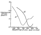
- the Figure shows absorption curves of the transmissive Optical Density versus Wavelength of radiation (nm) for coatings of 20 mg of Dye No. 19 and 80 mg of poly(methyl methacrylate) in 1 ml solutions. Two separate solvent blends are shown. Curve A is a blend of 2% (volume) ethanol in trichloromethane. Curve B is a blend of 10 % ethanol in trichloromethane.
- the elements of the present invention use a particular highly advantageous class of chain-substituted cyanine dyes.
- the dyes are advantageous not only in respect of their improved solubility in solvent and binder, but also their spectral characteristic in the near infrared region of the spectrum.
- the dyes retain a very high absorption in the near infrared when present in a layer in an optical recording element.
- the combination of infrared wavelength of absorption specificity, high extinction coefficient values and solubility leads to these dyes being particularly useful for laser addressed optical recording elements as will be described in detail hereinafter.
- the heterocyclic nuclei formed by Z 1 and Z 2 may be any of the wide range of nuclei known in the cyanine dye art. Generally, Z 1 and Z 2 each represent the non-metallic atoms necessary to complete a heterocyclic nucleus containing 5 to 6 atoms in the heterocyclic ring, the nucleus optionally possessing substituents.
- the heterocyclic ring is composed of ring atoms selected from C, N, 0, S and Se. Examples of such heterocyclic nuclei include :
- Z 1 and/or Z 2 complete a benzothiazole nucleus or a 3,3-dialkylindolenine nucleus.
- the groups R 1 and R 2 contain less than 8 carbon atoms. More preferably R 1 and R 2 are lower alkyl groups containing up to 4 carbon atoms.
- the alkyl groups may contain any substituent which does not deleteriously effect the properties of the dye as known in the cyanine art. Suitable substituted alkyl groups include alkoxyalkyl, benzyl and carboxyalkyl.
- R 3 and R 4 represent a hydrogen atom or a lower alkyl group containing 1 to 4 carbon atoms.
- R 3 and R 4 represent a hydrogen atom or a lower alkyl group containing 1 to 4 carbon atoms.
- R 5 to R 8 are hydrogen.
- certain substituted cyclopentanones are commercially available which may be used as intermediates in the preparation of the dyes of formula (I), e. g., 3-alkyl and 3-aryl materials such as 3-methylcyclopentanone and 3-phenylcyclopentanone and accordingly one of R 5 to R 8 may readily represent these substituents.
- the cyclic acid nuclei completed by the groups Q 1 and Q 2 preferably have the ring atoms selected from C, S, N, O and Se. Suitable moieties are derived from the following nuclei which may additionally possess substituents : 1,3-indandione, pyrazolone, isoxazolone ; e.
- Dyes of formula (I) are know.
- U.S. Patent No. 3,194,805 discloses a class of merocyanine and holopolar dyes containing arylene-chain substitution and their use as spectral sensitizing dyes for silver halide emulsions. Three of the dyes disclosed therein are within the scope of formula (I).
- United States Patent No. 2,955,939 discloses a class of dyes for spectral sensitization of silver halide, one of the dyes disclosed being within the scope of formula (I).
- Our copending European Patent Application EP-A-0101646, published on 29.02.84 discloses dyes of formula (I) together with their use in antihalation or acutance dyes.
- the recording elements of the present invention do not possess photosensitive materials ; e. g., silver halide, in association with the dye and rely upon the dye to absorb at the wavelength of the recording radiation.
- the dyes of formula (I) absorb in the near infrared when coated out in a polymeric binder and retain a high extinction coefficient at the absorption maximum.
- Preferred dyes for use in the invention are those in which the cyclic nucleus completed by Q 1 and Q 2 has the general formula : in which R 9 and R 10 independently represent a hydrogen atom, an alkyl or cycloalkyl group each of which may be substituted ; e. g., hydroxyalkyl, alkoxy-alkyl, alkoxycarbonyl, polyoxyalkyl, alkenyl or substituted alkenyl, an aryl group which may be substituted, or an aralkyl group, any of which groups may contain up to 25 carbon atoms.
- R 9 and R 10 together contain at least 8 carbon atoms and are aliphatic groups, or at least one of R 9 and R 10 is an alkyl chain substituted by solubility enhancing groups ; e. g., alkoxy substituents ; more preferably at least one of R 9 and R 10 represents an alkyl group containing at least 8 carbon atoms.
- Dyes containing such a moiety have particularly advantageous properties for the present invention, since substitution of this type has the benefit of enhancing the solubility of the dyes in both organic solvents and polymeric binders.
- the dyes of formula (I) may be prepared according to the methods described in United States Patent No. 2,955,939 and our copending European Patent Application EP-A-0 101 646. The synthesis involves the following stages :
- the asymetrical dyes may be prepared by a related two-step mechanism.
- dyes suitable for use in the recording medium for optical data storage include :
- dyes of formula (I) may, on coating and drying, lose some density at the primary near infrared absorption peak and develop a secondary shorter wavelength absorption peak. It has been found that this undesirable phenomenon is inhibited by the incorporation of bulky aliphatic groups onto the moiety completed by Q 1 and Q 2.
- the bulky groups are alkyl groups containing at least 18 carbon atoms, more preferably alkyl groups containing at least 12 carbon atoms.
- the undesirable development of the secondary absorption peak can be entirely suppressed by the judicious choice of solvent mixture and polymer.
- the accompanying draving shows absorption curves of cootings of Dye No. 29 and shows the effect of a change of solvent ratio upon the absorption curve of coatings of the dye in poly(methylmethacrylate), (PMMA). It can be seen that increasing the alcohol concentration to 10 % reduces the secondary absorption peak at 750 nm and gives only the desired absorption peak at 820 nm. Taking steps to avoid such a shift in absorption is desirable for good sensitivity as it ensures that the recording media has good sensitivity when used with laser diodes emitting in the restricted range 800 to 850 nm.
- dyes can be chosen from the compounds covered by formula (I) and can be used together to provide good sensitivity at wavelengths matching the source emission.
- the optical recording element of the invention may be in the form of a support having a recording layer coated thereon comprising one or more dyes of formula (I) optionally together with a binder, or the element may be in the form of a self-supporting structure ; e. g., a cast film, comprising a dye of formula (I) and a binder.
- the dye must be present in the region of the surface of the recording layer in a sufficient amount to absorb an effective amount of the exposing radiation to produce a visible mark on the surface thereof. It is not possible to generally quantify the minimum amount of dye required for optical density of the recording layer or element since the minimum amount will vary according to the dye, the thickness of the recording layer or the construction of a self-supporting element and the binder present. For example, a thick layer of recording medium having a high optical density and coating weight of dye may have inferior performance to a thin layer having a lower optical density and coating weight.
- Sufficient energy must be absorbed during writing to cause differentiation of exposed (or written) areas from those non-exposed. Most commonly a difference in reflectivity of the composition is measured : depending on the incidence angle of the writing laser beam the greater or lesser reflectivity may be accomodated.
- the thickness of the coated recording layer is an important factor in controlling the efficiency of the laser in forming pits since good writing sensitivity requires that writing energy be effectively coupled into the recording layer.
- sensitivity is improved as the thickness of the recording layer is reduced below 1 ⁇ Lm and in preferred embodiments the thickness is in the range from 30 to 400 nm, while a broader range of 10 to 1,000 nm is generally believed to be useful.
- the recording layer is generally coated onto a substrate which acts as a support.
- the support may be substantially any solid material, either flexible or rigid including polymeric materials ; e. g., polyacrylates, polyamides, polycarbonates, polyesters, polyolefins, polyurethanes and polyvinyl resins ; ceramic or glass materials ; fibrous materials and metals.
- the support must be stable enough to avoid deformation during writing of information.
- the surface of the substrate which is to be coated should be smooth and free of random surface irregularities, although it may be flat, pre-grooved or may include predetermined surface irregularities capable of being read by laser light in the final element to provide an indexing function or the like.
- a light reflecting layer is preferably provided between the substrate and the recording layer. Suitable materials include aluminium, copper, chromium, gold and rhodium. The thickness of the light reflecting layer should be sufficient to reflect a significant amount (e. g., at least 20 %, preferably at least 50 %) of the recording light. Leveling and/or priming layers may also be applied to the substrate before application of the reflective coating and/or dye containing layer. If the reflecting material itself can be formed so it is a self-sustaining layer and optically smooth, it. may constitute the substrate.
- a recording element in which there is both a reflecting layer and the recording layer is termed a bilayer system. This can be expanded to a trilayer system by the insertion of a spacer between the reflecting layer and the recording medium.
- the spacer may confer smoothness, help control the thermal performance of the medium and protect the reflecting layer.
- a dielectric spacer may comprise vacuum deposited Si0 2 , or an organic polymer which does not contain any of the light-absorbing dye.
- the dielectric spacer is preferably transparent to the laser beams used in reading and writing on the recording layer. Examples of the construction of such recording elements are disclosed in Bartolini et al., J. Quantum Electronics, 1981, page 69.
- the recorded information is carried in the form of marks ; e. g., about 1 micron in size, in the recording layer. Because of the high density of the information, dust or other foreign material on the top surface of the recording layer would cause significant errors. Therefore, in one embodiment of recording elements of the present invention a protective layer at least 0.6 ⁇ m thick is provided on top of the recording layer to separate dust and other particles from the recording layer. The laser beam is sharply convergent at the top surface of the recording layer and accordingly any dust particles on the protective layer would be out of focus with respect to the laser beam and thus not affect the reading and writing process.
- the protective layer can be made of any material which is transparent to laser beams used in reading and writing on the recording layer and it can either be directly in contact with the recording layer or separated from it by an air, unreactive gas ; e. g., nitrogen, gap or vacuum gap.
- Suitable materials which can be used for the protective coating include glass, poly(methylmethacrylate), polycarbonates and polyesters.
- the recording elements of the invention are double-sided comprising a planar substrate optionally in the form of a disc, having on each major surface a reflecting layer, above which is coated the recording medium and optionally a protective layer.
- a planar substrate optionally in the form of a disc, having on each major surface a reflecting layer, above which is coated the recording medium and optionally a protective layer.
- two disc-shaped substrates bearing firstly a reflective layer and secondly an absorbing layer with an optional overcoated protective layer may be adhered together by the surfaces not bearing the recording layer.
- a wide range of organic binders may be used to prepare the recording layer and elements for use in the invention.
- the binder should be capable of film formation in the recording element and be pellucid : cloudiness or milkiness of the binder at the writing laser emission are undesirable in the recording element.
- the binder may be colored and exhibit a degree of infrared absorbance at the writing laser emission.
- the binder must also adhere to the adjacent layers of the recording element ; e. g., substrate, reflecting spacer or protective layers.
- thermoplastic polymers are preferred, particularly those polymers having a Tg in the range 70 to 115 °C or capable of being formulated with plasticizers to provide a binder medium having a Tg in this range.
- Useful binders include cellulose acetate butyrate, polystyrene, polysulfonamide, polycarbonates (e. g., those commercially available from General Electrics Plastics under the trade name Lexan), cellulose nitrate, hydroabietyl alcohol (e. g., that commercially available from Hercules Chemical Company under the trade name Abitol AUK257), polyesters ; e.
- polyacrylates [poly(ethyl methacrylate), poly(methyl methacrylate) poly(isobutylmethacrylate), poly(biphenylacrylate)], poly(vinyl butyral), poly (vinyl acetate), polyethers, polyamines, poly(vinyl chloride), poly(vinyl alcohol) and copolymers such as arising from vinyl chloride and vinyl acetate monomers, and hydrogenated rosin ester (e. g., Staybelite Ester 10, commercially available from Hercules Powder Company).
- These binders may be used either singly or in combination with another.
- Preferred binders include polystyrene, poly(a-methylstyrene) and poly(methymethacrylate), either alone or containing Staybelite Ester 10.
- Anionic binders such as those derived from carboxylic acid containing copolymers may also be used. Such binders may be associated with the dye cation.
- Crosslinked binders e. g., epoxy resins, may also be used but generally with some loss in sensitivity. Both natural and synthetic binders are useable.
- the recording layer be an amorphous material since pronounced crystallization or graininess in the film may cause increased noise levels making the material unsuitable as a high quality recording medium.
- the dye be present in the.recording medium as microcrystals. Accordingly, the dye may either be solubilized in the binder or very finely dispersed. The former is preferred. For dispersions the particle size must be very much less than 1 micron.
- Crystallinity in the dye/polymer films can be detected visually by haziness of the coated layer or in extreme cases, as a metallic, highly reflective appearance to the film compared to amorphous films which present a completely transparent appearance. Crystallization may also be assessed through the use of X-ray diffraction.
- the particular dye/binder ratio selected is a balance between one end of the range where a high dye/binder ratio leads to the possibility of undesirable crystallization, whilst at the other extreme too little dye may result in insufficient heat transfer from the dye to the binder to cause melting and hence prevent recording.
- irradiation of the polymeric binder with the laser diode caused no marking of the surface.
- Another limitation on increasing the dye/binder ratio is the solubility of the dye in the coating solution.
- the percentage of binder relative to the total weight of dye and (any) binder may range from 0 to 97 %. Generally when binder is present it is employed in the range 5 to 80 %.
- the solubility of the dye is preferably at least 10 mg/ml in the solvent chosen and more preferably at least 30 mg/ml.
- the dyes of formula (I) have the desired solubility in organic solvents as well as in polymeric binders. With such dyes, ratios of dye/polymer of 1 : 1 w/w can be coated from solutions containing 6 % w/v total solids without crystallization occurring.
- the solvent used for preparing the coating composition may be selected from a wide range of known solvents such as chlorinated solvents ; e. g., chloroform, dichloromethane and 1.2-dichioroethane, or ketonic solvents ; e. g., cyclohexanone, or aromatic solvents ; e. g., xylene.
- the solvents can be used alone or in combination, the choice being governed to some extent by the particular dye/binder system and by the method of coating used.
- Suitable methods of coating the compositions include handcoating, dipcoating, spincoating and webcoating.
- a very suitable process is, in particular, the centrifugal spincoating process. According to this process, the substrate to be covered is laid on a turntable and a quantity of solution is then provided on the substrate. By rotating the substrate, the liquid will spread circularly over the surface of the substrate. It has been found in experiments that very thin layers can be obtained by means of the centrifuging process, the thickness of which depends inter alia on the rotation speed of the substrate and the viscosity of the solution to be spread.
- the dyes it is not essential for the dyes to be applied together with a polymeric binder and it is possible to coat the dyes on a substrate in the form of a simple solution and rapidly evaporate the solvent ; e. g., in an air current, to leave an amorphous film of dye on the surface of the substrate. It has been found that such coatings provide better sensitivity, comparable to that of a dye/binder system, although in some cases, the films may have inferior stability relative to the dye/polymer systems.
- a record blank comprising a substrate coated with a reflective layer, a recording medium of the invention and optional protective layer in the form of a disc is subjected to rotation at a constant rotational speed while a beam of light from a light source (e. g., a laser providing light at a wavelength at which the recording medium is absorbing) is focussed on the coated surface of the disc.
- a light source e. g., a laser providing light at a wavelength at which the recording medium is absorbing
- control is effected in accordance with carrier waves modulated in frequency by picture-representative video signals, with the light beam intensity varying as a result between a high level sufficient to effect ablation of the absorptive material and a low level insufficient to effect such ablation, the frequency of the level alternations varying as the video signal amplitude changes.
- An information track comprising a succession of spaced deformations is formed in the coated surface of the disc, the deformations appearing in those surface regions exposed to high-intensity beam, due to vaporization or melting of the absorptive layer material in response to the high-intensity beam exposure. Variations in the length and separation of the deformations are representative of the recorded information.
- a spiral information track may be formed by providing relative motion, in a radiation direction and at a constant rate during the recording between the recording beam and the rotating disc. Alternatively, in the absence of such relative motion during the recording, concentric circular information tracks may be formed.
- the surface of the substrate may bear a grooved, optically transparent spacer layer, this layer being formed by a cured photopolymer.
- the grooves normally concentric, are formed by exposure of the photopolymer through a mask.
- the grooved substrate is then optionally metallization coated with a recording layer formulation such that there is a sufficient quantity to form an optical record in each groove or band.
- the result of the above-described recording process is the formation of an information record of a form which facilitates recovery of the recorded information by optical playback processes.
- the information track of such an information record may comprise undisturbed surface regions that exhibit very low reflectance at an appropriate light frequency, alternating with pit regions, formed by the ablation process, that exhibit appreciably high reflectance at the same light frequency.
- a high ratio between the reflectance of the pit regions and the reflectance of the intervening (undisturbed surface) regions is readily provided.
- Media exhibiting lower reflectivity after writing may also be made.
- a light beam is focussed upon the information track of a rotating information record of the above described type.
- the playback beam has a constant intensity at a level insufficient to effect ablation of the disc coatings, and is of a frequency substantially corresponding to that at which the undisturbed surface regions exhibit an antireflection condition.
- a photodetector positioned to receive light reflected from the successive regions of the information track as they pass through the path of the focussed light, develops a signal representative of the recorded information.
- a high readout contrast ratio due to the large differences in reflectance of the pit regions and the intervening track regions, at the light frequency of the playback beam) is readily obtained, permitting recording of the recorded video signals with an excellent signal-to-noise ratio.
- An alternative construction has a non-absorbing substrate bearing the recording medium, the recording medium being coated with a reflective layer.
- the laser's incident beam passes through the substrate to the recording medium and hence the reflective layer.
- the elements of the invention may be used as a master element for the production of other elements which are capable of being read by laser light.
- Such master elements may use dyes which exhibit lower long-term stability.
- the above technique may be used to prepare substrates suitable for use in the recording elements of the invention, the substrates bearing surface irregularities to provide an indexing system or page numbering system for the resulting recording element.
- Polyester base was coated with a variety of dye/binder/solvent compositions by various techniques as reported in Table III in which the percentages of binder and dye are based upon the coating composition.
- the recording layers so generated were subjected to ablation using a Hitachi Laser Diode HLP-1400 emitting at 830 nm.
- the film was passed orthogonally across the incident, pulsing, laser beam in order to obtain a number of exposures for a given power and pulse duration. Because of focussing difficulties, the film was inclined at a small angle to the orthogonal so that the laser beam passed from being out of focus through the focus point to out of focus for a given series of identical pulses. The various exposures were then examined ; that with optimum focussing was selected. The diameter of this circular ablation pit was then measured.
- the power and duration figures for the « static threshold value were the minimum figures which will give the 1 micron spots.
- the power and pulse duration figures which were the minimum exposures for giving any ablation on the film were recorded as the figures which give « marks visible •. These marks were of much smaller diameter than 1 ⁇ m.
- Polyester base (76 ⁇ m) was coated using a K bar No. 1 with a series of different dyes from formulations containing poly(methyl methacrylate) dissolved in chloroform/ethanol (9/1 v/v) to the limit of their solubility.
- the dyes used and the ⁇ max of the coating are recorded in the following Table V.
- Polyester base (76 ⁇ m) was coated using a K bar No. 1 with Dye Nos. 29 and/or 34 in formulations containing poly(methyl methacrylate) (PMMA) dissolved in chloroform/ethanol (9/1 v/v).
- PMMA poly(methyl methacrylate)
- the dyes used, the dye/binder ratio and the ablation data obtained as in Examples 2 to 10 are reported in the following Table VI.
- Subbed polyester base (76 ⁇ m) was coated using a K Bar No. 1 by hand, or spin coating (at 200 to 400 rpm) with a solution of dye in chloroform/ethanol. The solvent was removed quickly by evaporation in an air current leaving a dye as an amorphous film on the surface of the base.
- Polyester base (76 ⁇ m) was coated using a K bar No. 1 with the formulations reported in the following Table VII.
- the ⁇ max for each layer is reported together with ablation data for certain Examples which was obtained as described in Examples 2 to 10. (See Tables VII pages 21-23)
- Formulations were prepared by dissolving selected dyes in poly(methyl methacrylate) solution in CHCI 3 /EtOH. The quantities of components and solvent balance was adjusted such that the dye was dissolved towards the limit of its solubility-in the formulation.
- the formulations were coated on a polyester base (76 ⁇ m) using a K bar No. 1. The dyes used and the properties of the coatings are reported in the following Table VIII.
Landscapes
- Optical Record Carriers And Manufacture Thereof (AREA)
- Thermal Transfer Or Thermal Recording In General (AREA)
Claims (25)


Priority Applications (1)
| Application Number | Priority Date | Filing Date | Title |
|---|---|---|---|
| AT84900465T ATE29612T1 (de) | 1982-12-31 | 1983-12-22 | Aufzeichnungsmaterial zur optischen speicherung von informationen. |
Applications Claiming Priority (2)
| Application Number | Priority Date | Filing Date | Title |
|---|---|---|---|
| GB8237040 | 1982-12-31 | ||
| GB8237040 | 1982-12-31 |
Publications (2)
| Publication Number | Publication Date |
|---|---|
| EP0130213A1 EP0130213A1 (de) | 1985-01-09 |
| EP0130213B1 true EP0130213B1 (de) | 1987-09-09 |
Family
ID=10535303
Family Applications (1)
| Application Number | Title | Priority Date | Filing Date |
|---|---|---|---|
| EP84900465A Expired EP0130213B1 (de) | 1982-12-31 | 1983-12-22 | Aufzeichnungsmaterial zur optischen speicherung von informationen |
Country Status (6)
| Country | Link |
|---|---|
| US (1) | US4551413A (de) |
| EP (1) | EP0130213B1 (de) |
| JP (1) | JPS60500329A (de) |
| CA (1) | CA1246379A (de) |
| DE (1) | DE3373585D1 (de) |
| WO (1) | WO1984002794A1 (de) |
Families Citing this family (27)
| Publication number | Priority date | Publication date | Assignee | Title |
|---|---|---|---|---|
| DE3372421D1 (en) * | 1982-12-31 | 1987-08-13 | Minnesota Mining & Mfg | Recording medium for optical data storage |
| GB2155811B (en) * | 1984-02-06 | 1987-01-21 | Ricoh Kk | Optical information recording medium |
| JPS60187948A (ja) * | 1984-03-06 | 1985-09-25 | Ricoh Co Ltd | 光学的情報記憶媒体 |
| DE3537539A1 (de) * | 1984-10-23 | 1986-04-24 | Ricoh Co., Ltd., Tokio/Tokyo | Optisches informationsaufzeichnungsmaterial |
| US4728724A (en) * | 1985-04-08 | 1988-03-01 | Hoechst Celanese Corporation | Optical data storage medium comprising a chromophore/polymer information layer |
| US4735839A (en) * | 1985-07-10 | 1988-04-05 | Ricoh Co., Ltd. | Optical information recording medium |
| US4757472A (en) * | 1986-12-31 | 1988-07-12 | Tecon Memory, Inc. | Electrophotographic optical memory system |
| US4968593A (en) * | 1987-02-27 | 1990-11-06 | Fuji Photo Film Co., Ltd. | Optical information recording medium |
| GB8720417D0 (en) * | 1987-08-28 | 1987-10-07 | Minnesota Mining & Mfg | Recording medium for optical data storage |
| GB8803416D0 (en) * | 1988-02-15 | 1988-03-16 | Minnesota Mining & Mfg | Polymeric polymethine dyes & optical data storage media containing same |
| DE3810642A1 (de) * | 1988-03-29 | 1989-10-12 | Basf Ag | Methinfarbstoffe sowie optisches aufzeichnungsmedium, enthaltend die neuen farbstoffe |
| US4950579A (en) * | 1988-07-08 | 1990-08-21 | Minnesota Mining And Manufacturing Company | Optical disc recording medium having a microstructure-derived inhomogeneity or anisotropy |
| CA2049362C (en) * | 1989-03-30 | 2001-07-03 | Diane M. Foley | Near infrared laser absorbing coating and method for using same in color imaging and proofing |
| GB8923921D0 (en) * | 1989-10-24 | 1989-12-13 | Minnesota Mining & Mfg | Optical recording elements |
| US5311246A (en) * | 1992-08-26 | 1994-05-10 | Graphic Arts Technical Foundation | Frequency modulated acutance guide and method of use |
| US20020064728A1 (en) * | 1996-09-05 | 2002-05-30 | Weed Gregory C. | Near IR sensitive photoimageable/photopolymerizable compositions, media, and associated processes |
| US5955224A (en) * | 1997-07-03 | 1999-09-21 | E. I. Du Pont De Nemours And Company | Thermally imageable monochrome digital proofing product with improved near IR-absorbing dye(s) |
| US5858583A (en) * | 1997-07-03 | 1999-01-12 | E. I. Du Pont De Nemours And Company | Thermally imageable monochrome digital proofing product with high contrast and fast photospeed |
| US6251571B1 (en) | 1998-03-10 | 2001-06-26 | E. I. Du Pont De Nemours And Company | Non-photosensitive, thermally imageable element having improved room light stability |
| JP2002074740A (ja) * | 2000-08-25 | 2002-03-15 | Hayashibara Biochem Lab Inc | 光記録媒体 |
| US20090081401A1 (en) * | 2000-08-25 | 2009-03-26 | Kabushiki Kaisha, Hayashibara, Seibutsu, Kagaku Kenky | Optical recording media |
| US6944115B2 (en) | 2000-09-29 | 2005-09-13 | General Electric Company | Colored data storage media |
| US6475589B1 (en) | 2001-12-17 | 2002-11-05 | General Electric Company | Colored optical discs and methods for making the same |
| US20040131969A1 (en) * | 2002-10-07 | 2004-07-08 | Fuji Photo Film Co., Ltd. | Non-resonant two-photon absorbing material, non-resonant two-photon emitting material, method for inducing absorption of non-resonant two-photons and method for generating emission of non-resonant two-photons |
| JP5283339B2 (ja) * | 2006-03-09 | 2013-09-04 | 富士フイルム株式会社 | 画像形成材料、画像形成方法、平版印刷版原版及び平版印刷方法 |
| JP2008159217A (ja) * | 2006-12-26 | 2008-07-10 | Fujifilm Corp | 光記録媒体の記録方法 |
| JP5352171B2 (ja) * | 2007-10-15 | 2013-11-27 | 富士フイルム株式会社 | 発光素子の製造方法および光学素子の製造方法 |
Family Cites Families (16)
| Publication number | Priority date | Publication date | Assignee | Title |
|---|---|---|---|---|
| US2813802A (en) * | 1955-02-24 | 1957-11-19 | Monsanto Chemicals | Infra-red filter media |
| US2955939A (en) * | 1956-09-13 | 1960-10-11 | Eastman Kodak Co | Holopolar cyanine dyes and photographic emulsions containing them |
| US3194805A (en) * | 1960-09-02 | 1965-07-13 | Eastman Kodak Co | Merocyanine and holopolar dyes containing arylene-chain substitution |
| JPS4917725B1 (de) * | 1970-12-14 | 1974-05-02 | ||
| JPS4864995A (de) * | 1971-12-07 | 1973-09-07 | ||
| US4000492A (en) * | 1974-04-04 | 1976-12-28 | Bell Telephone Laboratories, Incorporated | Metal film recording media for laser writing |
| US4137077A (en) * | 1976-01-29 | 1979-01-30 | Rca Corporation | Broadening the spatial frequency pass band of a thermoplastic layer |
| US4259433A (en) * | 1976-10-22 | 1981-03-31 | Fuji Photo Film Co., Ltd. | Method for producing disk-recording plates |
| JPS6045414B2 (ja) * | 1977-07-12 | 1985-10-09 | 富士写真フイルム株式会社 | リス型ハロゲン化銀写真感光材料 |
| GB2005155A (en) * | 1977-09-28 | 1979-04-19 | Rca Corp | Improved optical recording medium |
| NL7809159A (nl) * | 1977-09-29 | 1979-04-02 | Philips Nv | Informatieregistratie element met kleurstof bevattende hulplaag. |
| NL7905914A (nl) * | 1979-08-01 | 1981-02-03 | Philips Nv | Kleurstof bevattend laagje van een filmvormend polymeer bindmiddel en toepassing ervan in een informatie- registratieeelement. |
| CA1154963A (en) * | 1980-02-25 | 1983-10-11 | Harold T. Thomas | USE OF.alpha.,.alpha.'-BIS(DIALKYLAMINOBENZYLIDENE) KETONE DYES IN OPTICAL RECORDING ELEMENTS |
| DE3118058A1 (de) * | 1980-05-14 | 1982-03-11 | RCA Corp., 10020 New York, N.Y. | Aufzeichnungstraeger und verfahren zum schreiben einer informationsspur sowie zum loeschen einer in dem traeger gespeicherten information |
| US4465767A (en) * | 1981-11-27 | 1984-08-14 | Ricoh Company, Ltd. | Optical information recording medium |
| US4460665A (en) * | 1981-12-28 | 1984-07-17 | Ricoh Co., Ltd. | Optical information recording medium |
-
1983
- 1983-12-22 EP EP84900465A patent/EP0130213B1/de not_active Expired
- 1983-12-22 DE DE8484900465T patent/DE3373585D1/de not_active Expired
- 1983-12-22 WO PCT/US1983/002026 patent/WO1984002794A1/en not_active Ceased
- 1983-12-22 JP JP59500500A patent/JPS60500329A/ja active Pending
- 1983-12-23 US US06/564,938 patent/US4551413A/en not_active Expired - Lifetime
- 1983-12-30 CA CA000444474A patent/CA1246379A/en not_active Expired
Also Published As
| Publication number | Publication date |
|---|---|
| CA1246379A (en) | 1988-12-13 |
| EP0130213A1 (de) | 1985-01-09 |
| JPS60500329A (ja) | 1985-03-14 |
| WO1984002794A1 (en) | 1984-07-19 |
| DE3373585D1 (en) | 1987-10-15 |
| US4551413A (en) | 1985-11-05 |
Similar Documents
| Publication | Publication Date | Title |
|---|---|---|
| EP0130213B1 (de) | Aufzeichnungsmaterial zur optischen speicherung von informationen | |
| US4547444A (en) | Recording element for optical data storage | |
| JPH05230B2 (de) | ||
| EP0131032B1 (de) | Aufzeichnungsmaterial zur optischen speicherung von informationen | |
| JPH1071766A (ja) | 情報記録媒体及び色素化合物 | |
| JP2000132865A (ja) | 情報記録媒体用保護層及び情報記録媒体 | |
| JP2732275B2 (ja) | 光学記録媒体 | |
| JPH0125718B2 (de) | ||
| JPS6351187A (ja) | 光記録方法 | |
| JPS6367187A (ja) | 光情報記録媒体 | |
| JP3187408B2 (ja) | 情報記録媒体 | |
| JPS6083236A (ja) | 光学的情報記録媒体 | |
| JP2577253B2 (ja) | 光学記録媒体 | |
| JPS61163892A (ja) | 光学的記録及び読み出し方法 | |
| JPS63168393A (ja) | 光学情報記録媒体 | |
| JPS63168392A (ja) | 光学記録媒体 | |
| JPS62174193A (ja) | 光記録方法 | |
| JPS63155146A (ja) | 光感応性組成物 | |
| JPS58220792A (ja) | 光学記録媒体 | |
| JPS62174191A (ja) | 光記録方法 | |
| JPH10166732A (ja) | 光記録媒体 | |
| JPS63135943A (ja) | 光感応性成物 | |
| JPS62174192A (ja) | 光記録方法 | |
| JPS6349758A (ja) | 光記録読み取り方法 | |
| JPS63135942A (ja) | 光感応性組成物 |
Legal Events
| Date | Code | Title | Description |
|---|---|---|---|
| PUAI | Public reference made under article 153(3) epc to a published international application that has entered the european phase |
Free format text: ORIGINAL CODE: 0009012 |
|
| 17P | Request for examination filed |
Effective date: 19840808 |
|
| AK | Designated contracting states |
Designated state(s): AT BE CH DE FR GB LI LU NL SE |
|
| 17Q | First examination report despatched |
Effective date: 19860401 |
|
| GRAA | (expected) grant |
Free format text: ORIGINAL CODE: 0009210 |
|
| AK | Designated contracting states |
Kind code of ref document: B1 Designated state(s): AT BE CH DE FR GB LI LU NL SE |
|
| REF | Corresponds to: |
Ref document number: 29612 Country of ref document: AT Date of ref document: 19870915 Kind code of ref document: T |
|
| REF | Corresponds to: |
Ref document number: 3373585 Country of ref document: DE Date of ref document: 19871015 |
|
| ET | Fr: translation filed | ||
| PG25 | Lapsed in a contracting state [announced via postgrant information from national office to epo] |
Ref country code: LU Free format text: LAPSE BECAUSE OF NON-PAYMENT OF DUE FEES Effective date: 19871231 |
|
| PLBE | No opposition filed within time limit |
Free format text: ORIGINAL CODE: 0009261 |
|
| STAA | Information on the status of an ep patent application or granted ep patent |
Free format text: STATUS: NO OPPOSITION FILED WITHIN TIME LIMIT |
|
| 26N | No opposition filed | ||
| REG | Reference to a national code |
Ref country code: GB Ref legal event code: 732 |
|
| PGFP | Annual fee paid to national office [announced via postgrant information from national office to epo] |
Ref country code: GB Payment date: 19900922 Year of fee payment: 8 |
|
| PGFP | Annual fee paid to national office [announced via postgrant information from national office to epo] |
Ref country code: FR Payment date: 19901116 Year of fee payment: 8 |
|
| PGFP | Annual fee paid to national office [announced via postgrant information from national office to epo] |
Ref country code: CH Payment date: 19901119 Year of fee payment: 8 |
|
| PGFP | Annual fee paid to national office [announced via postgrant information from national office to epo] |
Ref country code: DE Payment date: 19901123 Year of fee payment: 8 |
|
| PGFP | Annual fee paid to national office [announced via postgrant information from national office to epo] |
Ref country code: SE Payment date: 19901126 Year of fee payment: 8 Ref country code: AT Payment date: 19901126 Year of fee payment: 8 |
|
| PGFP | Annual fee paid to national office [announced via postgrant information from national office to epo] |
Ref country code: LU Payment date: 19901214 Year of fee payment: 8 |
|
| PGFP | Annual fee paid to national office [announced via postgrant information from national office to epo] |
Ref country code: NL Payment date: 19901231 Year of fee payment: 8 |
|
| PGFP | Annual fee paid to national office [announced via postgrant information from national office to epo] |
Ref country code: BE Payment date: 19910114 Year of fee payment: 8 |
|
| EPTA | Lu: last paid annual fee | ||
| PG25 | Lapsed in a contracting state [announced via postgrant information from national office to epo] |
Ref country code: GB Effective date: 19911222 Ref country code: AT Effective date: 19911222 |
|
| PG25 | Lapsed in a contracting state [announced via postgrant information from national office to epo] |
Ref country code: SE Effective date: 19911223 |
|
| PG25 | Lapsed in a contracting state [announced via postgrant information from national office to epo] |
Ref country code: LI Effective date: 19911231 Ref country code: CH Effective date: 19911231 Ref country code: BE Effective date: 19911231 |
|
| BERE | Be: lapsed |
Owner name: MINNESOTA MINING AND MFG CY Effective date: 19911231 |
|
| PG25 | Lapsed in a contracting state [announced via postgrant information from national office to epo] |
Ref country code: NL Effective date: 19920701 |
|
| NLV4 | Nl: lapsed or anulled due to non-payment of the annual fee | ||
| GBPC | Gb: european patent ceased through non-payment of renewal fee | ||
| PG25 | Lapsed in a contracting state [announced via postgrant information from national office to epo] |
Ref country code: FR Effective date: 19920831 |
|
| REG | Reference to a national code |
Ref country code: CH Ref legal event code: PL |
|
| PG25 | Lapsed in a contracting state [announced via postgrant information from national office to epo] |
Ref country code: DE Effective date: 19920901 |
|
| REG | Reference to a national code |
Ref country code: FR Ref legal event code: ST |
|
| EUG | Se: european patent has lapsed |
Ref document number: 84900465.0 Effective date: 19920704 |