EP0130652B1 - Tête magnétique et procédé de fabrication - Google Patents
Tête magnétique et procédé de fabrication Download PDFInfo
- Publication number
- EP0130652B1 EP0130652B1 EP84200944A EP84200944A EP0130652B1 EP 0130652 B1 EP0130652 B1 EP 0130652B1 EP 84200944 A EP84200944 A EP 84200944A EP 84200944 A EP84200944 A EP 84200944A EP 0130652 B1 EP0130652 B1 EP 0130652B1
- Authority
- EP
- European Patent Office
- Prior art keywords
- gap
- synthetic resin
- moulding
- pole tip
- adhesion promotor
- Prior art date
- Legal status (The legal status is an assumption and is not a legal conclusion. Google has not performed a legal analysis and makes no representation as to the accuracy of the status listed.)
- Expired
Links
- 238000004519 manufacturing process Methods 0.000 title claims description 10
- 238000000465 moulding Methods 0.000 claims description 57
- 229920003002 synthetic resin Polymers 0.000 claims description 54
- 239000000057 synthetic resin Substances 0.000 claims description 54
- 239000000463 material Substances 0.000 claims description 30
- 238000000034 method Methods 0.000 claims description 26
- 229920005989 resin Polymers 0.000 claims description 17
- 239000011347 resin Substances 0.000 claims description 17
- 229910000859 α-Fe Inorganic materials 0.000 claims description 11
- 239000003822 epoxy resin Substances 0.000 claims description 10
- 229920000647 polyepoxide Polymers 0.000 claims description 10
- 239000004645 polyester resin Substances 0.000 claims description 8
- 229920001225 polyester resin Polymers 0.000 claims description 8
- -1 acrylic ester Chemical class 0.000 claims description 6
- 239000012298 atmosphere Substances 0.000 claims description 4
- QVGXLLKOCUKJST-UHFFFAOYSA-N atomic oxygen Chemical compound [O] QVGXLLKOCUKJST-UHFFFAOYSA-N 0.000 claims description 4
- 150000002148 esters Chemical class 0.000 claims description 4
- LNEPOXFFQSENCJ-UHFFFAOYSA-N haloperidol Chemical compound C1CC(O)(C=2C=CC(Cl)=CC=2)CCN1CCCC(=O)C1=CC=C(F)C=C1 LNEPOXFFQSENCJ-UHFFFAOYSA-N 0.000 claims description 4
- 229910052760 oxygen Inorganic materials 0.000 claims description 4
- 239000001301 oxygen Substances 0.000 claims description 4
- 239000002904 solvent Substances 0.000 claims description 4
- CBENFWSGALASAD-UHFFFAOYSA-N Ozone Chemical compound [O-][O+]=O CBENFWSGALASAD-UHFFFAOYSA-N 0.000 claims description 3
- 238000001704 evaporation Methods 0.000 claims description 3
- 230000005855 radiation Effects 0.000 claims description 3
- 239000000047 product Substances 0.000 description 9
- 238000012360 testing method Methods 0.000 description 7
- 229910044991 metal oxide Inorganic materials 0.000 description 6
- 150000004706 metal oxides Chemical class 0.000 description 6
- 229920002994 synthetic fiber Polymers 0.000 description 5
- 239000000853 adhesive Substances 0.000 description 4
- 230000001070 adhesive effect Effects 0.000 description 4
- 230000004048 modification Effects 0.000 description 4
- 238000012986 modification Methods 0.000 description 4
- ZWEHNKRNPOVVGH-UHFFFAOYSA-N 2-Butanone Chemical compound CCC(C)=O ZWEHNKRNPOVVGH-UHFFFAOYSA-N 0.000 description 3
- 238000005266 casting Methods 0.000 description 3
- 230000002349 favourable effect Effects 0.000 description 3
- 239000011521 glass Substances 0.000 description 3
- 238000010438 heat treatment Methods 0.000 description 3
- BPSIOYPQMFLKFR-UHFFFAOYSA-N trimethoxy-[3-(oxiran-2-ylmethoxy)propyl]silane Chemical compound CO[Si](OC)(OC)CCCOCC1CO1 BPSIOYPQMFLKFR-UHFFFAOYSA-N 0.000 description 3
- XDLMVUHYZWKMMD-UHFFFAOYSA-N 3-trimethoxysilylpropyl 2-methylprop-2-enoate Chemical compound CO[Si](OC)(OC)CCCOC(=O)C(C)=C XDLMVUHYZWKMMD-UHFFFAOYSA-N 0.000 description 2
- 230000002411 adverse Effects 0.000 description 2
- 230000008901 benefit Effects 0.000 description 2
- IISBACLAFKSPIT-UHFFFAOYSA-N bisphenol A Chemical compound C=1C=C(O)C=CC=1C(C)(C)C1=CC=C(O)C=C1 IISBACLAFKSPIT-UHFFFAOYSA-N 0.000 description 2
- 239000003795 chemical substances by application Substances 0.000 description 2
- QGBSISYHAICWAH-UHFFFAOYSA-N dicyandiamide Chemical compound NC(N)=NC#N QGBSISYHAICWAH-UHFFFAOYSA-N 0.000 description 2
- 239000011888 foil Substances 0.000 description 2
- 239000000696 magnetic material Substances 0.000 description 2
- 230000005415 magnetization Effects 0.000 description 2
- 239000006060 molten glass Substances 0.000 description 2
- 230000008569 process Effects 0.000 description 2
- 125000006850 spacer group Chemical group 0.000 description 2
- 125000001424 substituent group Chemical group 0.000 description 2
- UOCLXMDMGBRAIB-UHFFFAOYSA-N 1,1,1-trichloroethane Chemical compound CC(Cl)(Cl)Cl UOCLXMDMGBRAIB-UHFFFAOYSA-N 0.000 description 1
- KWVGIHKZDCUPEU-UHFFFAOYSA-N 2,2-dimethoxy-2-phenylacetophenone Chemical compound C=1C=CC=CC=1C(OC)(OC)C(=O)C1=CC=CC=C1 KWVGIHKZDCUPEU-UHFFFAOYSA-N 0.000 description 1
- DHTGRDDBCWWKQJ-UHFFFAOYSA-N 2-(2,2-dihydroxyethoxy)ethane-1,1-diol Chemical compound OC(O)COCC(O)O DHTGRDDBCWWKQJ-UHFFFAOYSA-N 0.000 description 1
- SVONRAPFKPVNKG-UHFFFAOYSA-N 2-ethoxyethyl acetate Chemical compound CCOCCOC(C)=O SVONRAPFKPVNKG-UHFFFAOYSA-N 0.000 description 1
- LCFVJGUPQDGYKZ-UHFFFAOYSA-N Bisphenol A diglycidyl ether Chemical compound C=1C=C(OCC2OC2)C=CC=1C(C)(C)C(C=C1)=CC=C1OCC1CO1 LCFVJGUPQDGYKZ-UHFFFAOYSA-N 0.000 description 1
- 239000004593 Epoxy Substances 0.000 description 1
- BLRPTPMANUNPDV-UHFFFAOYSA-N Silane Chemical compound [SiH4] BLRPTPMANUNPDV-UHFFFAOYSA-N 0.000 description 1
- 125000005396 acrylic acid ester group Chemical group 0.000 description 1
- 230000009471 action Effects 0.000 description 1
- 125000003545 alkoxy group Chemical group 0.000 description 1
- 125000000217 alkyl group Chemical group 0.000 description 1
- 230000001588 bifunctional effect Effects 0.000 description 1
- 239000000969 carrier Substances 0.000 description 1
- 239000007795 chemical reaction product Substances 0.000 description 1
- 210000000078 claw Anatomy 0.000 description 1
- 239000011248 coating agent Substances 0.000 description 1
- 238000000576 coating method Methods 0.000 description 1
- 150000001875 compounds Chemical class 0.000 description 1
- 125000004122 cyclic group Chemical group 0.000 description 1
- 230000001419 dependent effect Effects 0.000 description 1
- GYZLOYUZLJXAJU-UHFFFAOYSA-N diglycidyl ether Chemical compound C1OC1COCC1CO1 GYZLOYUZLJXAJU-UHFFFAOYSA-N 0.000 description 1
- 125000003700 epoxy group Chemical group 0.000 description 1
- 230000008020 evaporation Effects 0.000 description 1
- 238000002474 experimental method Methods 0.000 description 1
- 239000007792 gaseous phase Substances 0.000 description 1
- 238000000227 grinding Methods 0.000 description 1
- 238000011065 in-situ storage Methods 0.000 description 1
- 239000003999 initiator Substances 0.000 description 1
- 229910052809 inorganic oxide Inorganic materials 0.000 description 1
- 230000003993 interaction Effects 0.000 description 1
- 238000003754 machining Methods 0.000 description 1
- 238000005259 measurement Methods 0.000 description 1
- 239000000203 mixture Substances 0.000 description 1
- 150000002902 organometallic compounds Chemical class 0.000 description 1
- 150000001282 organosilanes Chemical class 0.000 description 1
- 150000002978 peroxides Chemical class 0.000 description 1
- 239000004033 plastic Substances 0.000 description 1
- 229920003217 poly(methylsilsesquioxane) Polymers 0.000 description 1
- 229920000728 polyester Polymers 0.000 description 1
- 125000002924 primary amino group Chemical group [H]N([H])* 0.000 description 1
- 229910000077 silane Inorganic materials 0.000 description 1
- 239000007787 solid Substances 0.000 description 1
- 238000009987 spinning Methods 0.000 description 1
- 238000004544 sputter deposition Methods 0.000 description 1
- 239000000758 substrate Substances 0.000 description 1
- 229920001169 thermoplastic Polymers 0.000 description 1
- 229920001187 thermosetting polymer Polymers 0.000 description 1
- 239000004416 thermosoftening plastic Substances 0.000 description 1
- 229920006305 unsaturated polyester Polymers 0.000 description 1
Images

Classifications
-
- G—PHYSICS
- G11—INFORMATION STORAGE
- G11B—INFORMATION STORAGE BASED ON RELATIVE MOVEMENT BETWEEN RECORD CARRIER AND TRANSDUCER
- G11B5/00—Recording by magnetisation or demagnetisation of a record carrier; Reproducing by magnetic means; Record carriers therefor
- G11B5/127—Structure or manufacture of heads, e.g. inductive
- G11B5/187—Structure or manufacture of the surface of the head in physical contact with, or immediately adjacent to the recording medium; Pole pieces; Gap features
- G11B5/23—Gap features
- G11B5/232—Manufacture of gap
-
- G—PHYSICS
- G11—INFORMATION STORAGE
- G11B—INFORMATION STORAGE BASED ON RELATIVE MOVEMENT BETWEEN RECORD CARRIER AND TRANSDUCER
- G11B5/00—Recording by magnetisation or demagnetisation of a record carrier; Reproducing by magnetic means; Record carriers therefor
- G11B5/127—Structure or manufacture of heads, e.g. inductive
- G11B5/187—Structure or manufacture of the surface of the head in physical contact with, or immediately adjacent to the recording medium; Pole pieces; Gap features
- G11B5/23—Gap features
- G11B5/235—Selection of material for gap filler
Definitions
- the invention relates to a method of manufacturing a magnetic head comprising a magnetic core provided with pole tips which limit a non-magnetic gap of small length in which a first and a second moulding of ferrite each having a gap-limiting pole tip surface are used.
- Such a method is known from US-A-3,656,229 and .
- a magnetic head manufactured by that method can be used for recording, reproducing and/or erasing magnetic information in a track of a magnetic information carrier.
- the gap in the magnetic core of a magnetic head is of essential importance for the quality of a magnetic head: the length of the gap should be small to very small dependent upon the envisaged application of the magnetic head, while also the permissible tolerance of the gap length is very small.
- a gap length of approximately 0.25 pm is aimed at; in the case of an information carrier of the perpendicular magnetization type, a gap length of approximately 0.1 pm is aimed at.
- the material with which the gap is filled and the adhesion of this material to the gap-limiting surfaces of the pole tips are important for the durability of the magnetic head.
- gap length is to be understood to mean herein the dimension of the gap which corresponds to the distance between the gap limiting surfaces of the pole tips.
- magnetic heads are obtained by providing on a magnetic core part a layer of a non-magnetic metal oxide or metal oxide mixture as a material filling the gap and determining the length of the gap.
- the core part is heated for this purpose to a comparatively high temperature (400-800°C) in contact with the vapour of one or more organometallic compounds.
- a second core part which may be provided with such a metal oxide layer, is adhered to the first part by means of an adhesive.
- adhesives are glass and synthetic resins, but the patent gives preference to glass because synthetic resins would swell to an undesired extent.
- the magnetic heads obtained have a gap length of 0.8-1.2 pm.
- this gap length is too large.
- Other disadvantages of these known magnetic heads are that the metal oxide layer is deposited from the gaseous phase at a high temperature. In the manufacture of magnetic heads, this step is time-consuming and expensive, while the step of filling the slit between two core parts with molten glass is difficult to control. It is moreover desirable to provide both core parts with a metal oxide layer in order to prevent interaction between the glass and a core part not coated with metal oxide. In this magnetic head, the gap consequently has a filling composed of two or three layers. The accuracy with which the gap length is adjusted therefore depends in this known magnetic head upon the accuracy with which the desired thickness of each of the two or, in the preferred case, three layers is obtained.
- One object of the invention is to provide a method of manufacturing a magnetic head which can be readily carried out and by which a magnetic head having a gap of small length and great strength is obtained.
- Said object is achieved in a method of manufacturing a magnetic head mentioned in the openings paragraph, characterized in that the gap-limiting pole tip surfaces of the first and second mouldings are cleaned by means of a plasma discharge in an oxygen atmosphere or with ultraviolet radiation in an ozone atmosphere, an adhesion promotor and a solution of a synthetic resin chosen from the group comprising epoxy resins, acrylic ester resins and polyester resins are applied to the cleaned gap-limiting pole tip surface of the first moulding and the first moulding is spun about an axis at right angles to its gap-limiting pole tip surface, the solvent evaporating, the second moulding is arranged with its gap-limiting pole tip surface opposed to the gap-limiting pole tip surface of the first moulding, and then the synthetic resin is cured while the second moulding is pressed against the synthetic resin and the gap-limiting pole tip surface is in contact with the adhesion promotor, locating the gap-limiting pole tip surfaces at a distance of at most 0.5 pm from each other, and the two mouldings are adhered together at an elevated temperature.
- adhesion promotor is to be understood herein to means a bifunctional compound which can be chemically bonded on the one hand to the material of the pole tip and on the other hand to the synthetic resin.
- the reaction product can be considered as a synthetic resin with substituents which have been chemically bounded or can be chemically bonded to the pole tip material.
- an adhesion promotor with an epoxy resin, for example, a trialkoxy-alkylsilane may be used in which the alkyl group has a substituent reactive with the epoxy resin, such as an amino or an epoxy group. The alkoxy groups can form oxygen brides with the magnetic material.
- adhesion promotor is known per se from US-A-4.247.354, in which it is described that the bonding between thermoplastic or thermosetting resins and specific inorganic oxide substrates can be improved by means of hydrolytically reactful organosilane.
- the method according to the invention has the great advantages of accuracy, simplicity and rapidity.
- the method is excellently reproducible when the same concentration of the resin in the solvent, the same speed of revolution of the moulding to be coated and the same pressure during curing are maintained.
- the steps of applying the resin and of curing it are effected rapidly, while a temperature of up to approximately 250°C is sufficient for curing. Due to this low temperature, no or substantially no stresses are produced in the magnetic material during the manufacture of the magnetic head.
- the method according to the invention has the advantage that only one gap-filling material need be applied. It is to be noted that from DE-B-1184979 a method is known per se so as to put a casting resin as non-magnetisable material into the gap of a magnetic head. According to this known method the pole faces of the core limbs are brushed with a casting resin which can be cured and compressed to such an extent that a gaplength of approximately 1 ⁇ m is realised after curing of the casting resin.
- an adhesion promotor and a solution of the synthetic resin are also applied to the gap-limiting pole tip surface of the second moulding and the second moulding is spun about an axis at right angles to its gap-limiting pole tip surface. Due to the simplicity of the method and due to the fact that the process conditions can be readily maintained, the modifications of the method, in which both gap-limiting pole tip surfaces are coated with synthetic resin, is not disadvantageous and with this modification magnetic heads can be manufactured in a reproducible manner.
- the mouldings may be immersed with these surfaces in a solution of the adhesion promotor.
- these surfaces may be exposed to the vapour of the adhesion promotor, for example in an evacuated container.
- a monomolecular skin is sufficient.
- the skin is allowed to be a monomolecular layer so that this skin is extremely thin, while on the other hand the gap length is determined by the thickness of the layer of synthetic resin and the pressure exerted during the curing step.
- the synthetic resin is an acrylic ester resin.
- the acrylic ester resin can be promoted with, for example, methacryloxy propyltrimethoxysilane.
- the product of the method may be machined, if desired, for example, to obtain therefrom a number of magnetic heads by sawing. It is also possible to the reduce the width of the gap (i.e. the dimension of the gap along the pole face of the magnetic head and parallel to the gap-limiting pole tip surfaces) by removing pole tip material and hence synthetic resin adhered thereto. Further, a coil chamber (a space to be traversed by wire turns) may be formed or enlarged, for example, by means of a laser. The synthetic resin present in the gap in fact does not interfere with these machining operations.
- Another object of the invention is to provide a magnetic head of which the gap length is very small and which magnetic head can be readily manufactured and has a great mechanical strength.
- a magnetic head obtainedably with the aforementioned method according to the invention, comprising a magnetic core provided with pole tips of ferrite which limit a gap having a small length and being filled with non-magnetizable material which adheres the pole tips to each other, characterized in that the material filling the gap and adhering the pole tips to each other is a synthetic resin chosen from the group comprising epoxy resins, acrylic ester resins and polyester resins, an adhesion promotor is used at the interfaces between the pole tips and the synthetic resin, and the gap length is at most 0.5 pm.
- the magnetic head according to the invention has a high durability: that it is resistant to changing climatic conditions, has a great mechanical strength (large to very large forces are required to eliminate the adherence between the pole tips) and has a high resistance to wear.
- the pole face of the magnetic head had been treated with an abrasive belt, the pole tips at the pole face and the material in the gap were uniformly worn off. No material had been broken from the gap-limiting surfaces of the pole tips, which usually consist of Mn-Zn-ferrite.
- the gap filling of the magnetic head according to the invention comprises a simple or substantially simple layer.
- the quality of the magnetic head is further illustrated by the fact that the magnetic core can be subjected to the operation of a laser, for example in order to form a space for the magnetic coil or in order to reduce the width of the gap at the running surface without the gap, its filling and the adhesion of the filling to the pole tips being noticeably adversely affected.
- gaps of the magnetic head such as a rear gap, may be filled with a similar promoted synthetic resin.
- the magnetic head shown in Fig. 1 has a magnetic core comprising two parts 1, 2 each provided with a pole tip 3 and 4, respectively.
- the pole tips 3, 4 limit a gap 5 having a gap length of at most 0.5 pm.
- the relative direction of movement of a magnetic information carrier, which co-operates with the magnetic head, is indicated by the arrow V.
- the term "gap length" is to be understood to mean the dimension of the gap 5 in the direction of the arrow V.
- the gap 5 is filled with synthetic resin as a non-magnetizable material.
- the synthetic resin adheres the pole tips 3, 4 to each other.
- the opposed surfaces of the pole tips 3, 4 to which the synthetic resin adheres are designated in this specification "gap-limiting surfaces".
- a pole face 10 is the surface of the magnetic head along which the information carrier is passed during recording, reproducing or erasing of magnetic information.
- corresponding parts are each designated by a reference numeral which is 10 higher than the numerals used in Fig. 1. Dotted lines indicate that magnetic heads can be obtained from this assembly, for example, by sawing.
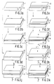
- Fig. 3a shows a first moulding 11 of magnetizable material corresponding to that shown in Fig. 2.
- the moulding has a part 13 from which a pole tip is formed later.
- Reference numeral 16 denotes a first gap-limiting pole tip surface.
- the moulding of Fig. 3b is formed from the moulding of Fig. 3a by applying an adhesion promotor skin 21 to the first gap-limiting pole tip surface 16 (Fig. 3a). (In order to visualize this skin, it is shown here and elsewhere, as layers of synthetic resin are, in a disproportionately large thickness).
- the skin 21 is obtained by contacting the surface 16 with the vapour of the adhesion promotor.
- Fig. 3e shows a second moulding 12 of magnetizable material as shown in Fig. 2.
- a second pole tip is formed from the part denoted by 14, while reference numeral 17 designates the second gap-limiting pole tip surface (i.e. the gap-limiting surface of this second pole tip).
- reference numeral 21 denotes in Fig. 3f a promotor skin.
- a layer 22 of synthetic resin as a non-magnetizable material is applied to the moulding of Fig. 3b by applying a solution of a synthetic resin to the first gap-limiting pole tip surface 16 provided with a promotor skin 21 and by rotating the moulding about an axis at right angles to this surface 16, during which process the solvent is thrust away and evaporates.
- the product shown in Fig. 3c and that shown in Fig. 3f are united in Fig. 3g with the first gap-limiting pole tip surface 16 and the second gap-limiting pole tip surface 17 facing each other and with the interposed synthetic resin layer 22 interposed between the surfaces 16 and 17. While the second moulding 12 is pressed against the layer 22 of synthetic resin so that the second gap-limiting pole piece surface 17 is located at a distance of at most 0.5 pm from the first gap-limiting pole piece surface 16, the synthetic resin is cured and adheres to the said gap-limiting surfaces 16 and 17, thus forming the gap 15'.
- the first moulding 11 is provided with a layer 22 of a synthetic resin applied in the manner described with reference to Fig. 3c and is provided with an adhesion promotor dispersed in the layer 22 of synthetic resin obtained by dissolving an adhesion promotor in the solution of synthetic resin.
- Fig. 3j shows a modification of the method, obtained by combining two products according to Fig. 3d. Similarly in Fig. 3k two products according to Fig. 3c are combined, In the products of Fig. 3j and Fig. 3k, respectively, for example by means of a laser a coil chamber may be provided.
- Mouldings of ferrite as magnetizable material are cleaned by means of a plasma discharge in oxygen or with ozone, for example generated in situ in air by means of an ultraviolet radiation source.
- the mouldings were contacted at 0.01 bar with the vapour of 3-glycidoxypropyltrimethoxysilane as adhesion promotor.
- a 3% by weight solution of the diglycidyl ether of disphenol A in methyl ethyl ketone and, as a curing agent, dicyanodiamide was applied to a first moulding.
- the moulding whose coated surface had dimensions of 0.8x1.6 cm, was spun at 1500 revolutions/min.
- the second moulding was positioned with respect to the first moulding and urged with 27 bar.
- the epoxy resin was cured under pressure at 200°C. The length of the gap obtained was 0.2 pm.
- a 15% by weight solution of the same material in monoethylglycol was applied to a similar moulding.
- the moulding was spun at 3500 revolutions/min. After positioning a second moulding, a gap of 0.1 ⁇ m was obtained under the same conditions.
- the products obtained were tested with respect to their tearing resistance partly immediately and partly after having been subjected to a cyclic moisture test.
- the products are kept for 1.5 hours at 25°C, are heated in 2 hours to 65°C, are kept for 2 hours at 65°C and are cooled in 2 hours to 25°C.
- the relative humidity is kept at 93% during this cycle.
- the test is continued for 10 days according to this schedule. For many applications of magnetic heads, this test is more severe than practical conditions.
- Example 2b) the polyester resin has a higher resistance to these extreme conditions than the epoxy resin.
Landscapes
- Engineering & Computer Science (AREA)
- Manufacturing & Machinery (AREA)
- Magnetic Heads (AREA)
Claims (9)
Priority Applications (1)
| Application Number | Priority Date | Filing Date | Title |
|---|---|---|---|
| AT84200944T ATE33077T1 (de) | 1983-07-04 | 1984-06-29 | Magnetkopf und herstellungsverfahren. |
Applications Claiming Priority (4)
| Application Number | Priority Date | Filing Date | Title |
|---|---|---|---|
| NL8302364 | 1983-07-04 | ||
| NL8302364 | 1983-07-04 | ||
| NL8401383 | 1984-05-02 | ||
| NL8401383A NL8401383A (nl) | 1983-07-04 | 1984-05-02 | Magneetkop en werkwijze voor zijn vervaardiging. |
Publications (2)
| Publication Number | Publication Date |
|---|---|
| EP0130652A1 EP0130652A1 (fr) | 1985-01-09 |
| EP0130652B1 true EP0130652B1 (fr) | 1988-03-16 |
Family
ID=26645872
Family Applications (1)
| Application Number | Title | Priority Date | Filing Date |
|---|---|---|---|
| EP84200944A Expired EP0130652B1 (fr) | 1983-07-04 | 1984-06-29 | Tête magnétique et procédé de fabrication |
Country Status (4)
| Country | Link |
|---|---|
| EP (1) | EP0130652B1 (fr) |
| KR (1) | KR920004997B1 (fr) |
| DE (1) | DE3469968D1 (fr) |
| NL (1) | NL8401383A (fr) |
Families Citing this family (3)
| Publication number | Priority date | Publication date | Assignee | Title |
|---|---|---|---|---|
| JPS61110317A (ja) * | 1984-11-01 | 1986-05-28 | Sanyo Electric Co Ltd | 磁気ヘツド |
| NL8501491A (nl) * | 1985-05-24 | 1986-12-16 | Philips Nv | Magneetkern. |
| KR102694748B1 (ko) * | 2017-02-03 | 2024-08-13 | 주식회사 디엔솔루션즈 | 공작기계 |
Family Cites Families (15)
| Publication number | Priority date | Publication date | Assignee | Title |
|---|---|---|---|---|
| DE961662C (de) * | 1953-09-10 | 1957-04-11 | Telefunken Gmbh | Spaltfuellung fuer Magnetisierungskopf |
| GB917824A (en) * | 1958-05-12 | 1963-02-06 | Thermionic Products Electronic | Improvements in or relating to magnetic transducing heads |
| DE1184979B (de) * | 1958-06-04 | 1965-01-07 | Loewe Opta Ag | Verfahren zur Herstellung eines Aufnahme- und/oder Wiedergabemagnetkopfes |
| US3188400A (en) * | 1961-01-09 | 1965-06-08 | Ampex | Ferrite coating |
| US3229355A (en) * | 1962-01-02 | 1966-01-18 | Ibm | Method of making a magnetic transducer head |
| US3494026A (en) * | 1962-08-13 | 1970-02-10 | Matsushita Electric Industrial Co Ltd | Methods for manufacturing magnetic heads |
| FR1506202A (fr) * | 1966-01-11 | 1967-12-15 | Clevite Corp | Tête transductrice magnétique |
| BE754795A (fr) * | 1969-08-14 | 1971-01-18 | Bull General Electric | Unite de tetes magnetiques multivoie et son procede de fabrication |
| AU416635B2 (en) * | 1969-09-29 | 1971-08-27 | The Australian National University | A method of bonding metal to metal or other materials |
| AT332508B (de) * | 1974-12-06 | 1976-10-11 | Teich Ag Folienwalzwerk | Verfahren zum aufbringen eines haftvermittlers |
| AT340158B (de) * | 1976-05-17 | 1977-11-25 | Eumig | Verfahren zur herstellung eines magnetkopfes und nach diesem verfahren hergestellter magnetkopf |
| JPS53123913A (en) * | 1977-04-05 | 1978-10-28 | Olympus Optical Co Ltd | Magnetic head and production of the same |
| US4172318A (en) * | 1977-08-17 | 1979-10-30 | Huntt Robert L | Method of joining manganese zinc ferrite pole pieces |
| US4247354A (en) * | 1978-10-02 | 1981-01-27 | Union Carbide Corporation | Bonding thermoplastic or thermosetting resins |
| NL8101515A (nl) * | 1981-03-27 | 1982-10-18 | Philips Nv | Optisch uitleesbare informatieschijf en werkwijze voor de vervaardiging ervan. |
-
1984
- 1984-05-02 NL NL8401383A patent/NL8401383A/nl not_active Application Discontinuation
- 1984-06-29 EP EP84200944A patent/EP0130652B1/fr not_active Expired
- 1984-06-29 DE DE8484200944T patent/DE3469968D1/de not_active Expired
- 1984-07-03 KR KR1019840003840A patent/KR920004997B1/ko not_active Expired
Also Published As
| Publication number | Publication date |
|---|---|
| KR850001596A (ko) | 1985-03-30 |
| EP0130652A1 (fr) | 1985-01-09 |
| DE3469968D1 (en) | 1988-04-21 |
| KR920004997B1 (ko) | 1992-06-22 |
| NL8401383A (nl) | 1985-02-01 |
Similar Documents
| Publication | Publication Date | Title |
|---|---|---|
| EP0130652B1 (fr) | Tête magnétique et procédé de fabrication | |
| US4745505A (en) | Magnetic head with a modified gap filler | |
| US4571651A (en) | Method of manufacturing a magnetic head assembly and product | |
| EP0138580B1 (fr) | Tête magnétique d'enregistrement en alliage | |
| JPS60223012A (ja) | 磁気ヘツド | |
| JPS6470917A (en) | Recording medium | |
| JP2765858B2 (ja) | 磁界変調型デイスク | |
| JP3015900B2 (ja) | 光ディスクメモリーの作製方法 | |
| JP2633273B2 (ja) | 研磨方法及び研磨用治具 | |
| JPS60160012A (ja) | 磁気ヘツドの製造方法 | |
| JPS6376130A (ja) | 光デイスクの製造方法 | |
| RU2071125C1 (ru) | Магнитная головка | |
| JPS5774821A (en) | Manufacture of magnetic resistance effect type magnetic head | |
| JPH0227372Y2 (fr) | ||
| JP2000311309A (ja) | 磁気ヘッド及び磁気ヘッドの製造方法 | |
| JPS6376103A (ja) | 磁気ヘツド及びその製造方法 | |
| JPS6224845B2 (fr) | ||
| JPH08273109A (ja) | 磁気ヘッドコアおよびその製造方法 | |
| JPH0954997A (ja) | 光磁気ディスクの製造方法 | |
| JPH0246510A (ja) | 磁気ヘッドコアおよびその製造方法 | |
| JPS61104307A (ja) | 磁気ヘツドの製造方法 | |
| JPS62209710A (ja) | 磁気ヘツド | |
| JPS59191120A (ja) | 磁気コアの製造方法 | |
| JPS62124608A (ja) | 磁気ヘツド | |
| JPS61177612A (ja) | 磁気ヘツドコアの樹脂接着方法 |
Legal Events
| Date | Code | Title | Description |
|---|---|---|---|
| PUAI | Public reference made under article 153(3) epc to a published international application that has entered the european phase |
Free format text: ORIGINAL CODE: 0009012 |
|
| AK | Designated contracting states |
Designated state(s): AT DE FR GB IT NL |
|
| 17P | Request for examination filed |
Effective date: 19850311 |
|
| 17Q | First examination report despatched |
Effective date: 19860717 |
|
| GRAA | (expected) grant |
Free format text: ORIGINAL CODE: 0009210 |
|
| AK | Designated contracting states |
Kind code of ref document: B1 Designated state(s): AT DE FR GB IT NL |
|
| REF | Corresponds to: |
Ref document number: 33077 Country of ref document: AT Date of ref document: 19880415 Kind code of ref document: T |
|
| REF | Corresponds to: |
Ref document number: 3469968 Country of ref document: DE Date of ref document: 19880421 |
|
| ITF | It: translation for a ep patent filed | ||
| ET | Fr: translation filed | ||
| PLBE | No opposition filed within time limit |
Free format text: ORIGINAL CODE: 0009261 |
|
| STAA | Information on the status of an ep patent application or granted ep patent |
Free format text: STATUS: NO OPPOSITION FILED WITHIN TIME LIMIT |
|
| 26N | No opposition filed | ||
| PGFP | Annual fee paid to national office [announced via postgrant information from national office to epo] |
Ref country code: AT Payment date: 19900620 Year of fee payment: 7 |
|
| PGFP | Annual fee paid to national office [announced via postgrant information from national office to epo] |
Ref country code: NL Payment date: 19900630 Year of fee payment: 7 |
|
| PG25 | Lapsed in a contracting state [announced via postgrant information from national office to epo] |
Ref country code: AT Effective date: 19910629 |
|
| PG25 | Lapsed in a contracting state [announced via postgrant information from national office to epo] |
Ref country code: NL Effective date: 19920101 |
|
| NLV4 | Nl: lapsed or anulled due to non-payment of the annual fee | ||
| PGFP | Annual fee paid to national office [announced via postgrant information from national office to epo] |
Ref country code: DE Payment date: 19930827 Year of fee payment: 10 |
|
| PGFP | Annual fee paid to national office [announced via postgrant information from national office to epo] |
Ref country code: GB Payment date: 19940527 Year of fee payment: 11 |
|
| PGFP | Annual fee paid to national office [announced via postgrant information from national office to epo] |
Ref country code: FR Payment date: 19940629 Year of fee payment: 11 |
|
| ITTA | It: last paid annual fee | ||
| PG25 | Lapsed in a contracting state [announced via postgrant information from national office to epo] |
Ref country code: DE Effective date: 19950301 |
|
| ITPR | It: changes in ownership of a european patent |
Owner name: CAMBIO RAGIONE SOCIALE;PHILIPS ELECTRONICS N.V. |
|
| PG25 | Lapsed in a contracting state [announced via postgrant information from national office to epo] |
Ref country code: GB Effective date: 19950629 |
|
| GBPC | Gb: european patent ceased through non-payment of renewal fee |
Effective date: 19950629 |
|
| PG25 | Lapsed in a contracting state [announced via postgrant information from national office to epo] |
Ref country code: FR Effective date: 19960229 |
|
| REG | Reference to a national code |
Ref country code: FR Ref legal event code: ST |