EP0131216A2 - Flüssigkristallanzeige - Google Patents
Flüssigkristallanzeige Download PDFInfo
- Publication number
- EP0131216A2 EP0131216A2 EP84107507A EP84107507A EP0131216A2 EP 0131216 A2 EP0131216 A2 EP 0131216A2 EP 84107507 A EP84107507 A EP 84107507A EP 84107507 A EP84107507 A EP 84107507A EP 0131216 A2 EP0131216 A2 EP 0131216A2
- Authority
- EP
- European Patent Office
- Prior art keywords
- liquid crystal
- angle
- crystal display
- polarizer
- orientation
- Prior art date
- Legal status (The legal status is an assumption and is not a legal conclusion. Google has not performed a legal analysis and makes no representation as to the accuracy of the status listed.)
- Granted
Links
Images


Classifications
-
- G—PHYSICS
- G02—OPTICS
- G02F—OPTICAL DEVICES OR ARRANGEMENTS FOR THE CONTROL OF LIGHT BY MODIFICATION OF THE OPTICAL PROPERTIES OF THE MEDIA OF THE ELEMENTS INVOLVED THEREIN; NON-LINEAR OPTICS; FREQUENCY-CHANGING OF LIGHT; OPTICAL LOGIC ELEMENTS; OPTICAL ANALOGUE/DIGITAL CONVERTERS
- G02F1/00—Devices or arrangements for the control of the intensity, colour, phase, polarisation or direction of light arriving from an independent light source, e.g. switching, gating or modulating; Non-linear optics
- G02F1/01—Devices or arrangements for the control of the intensity, colour, phase, polarisation or direction of light arriving from an independent light source, e.g. switching, gating or modulating; Non-linear optics for the control of the intensity, phase, polarisation or colour
- G02F1/17—Devices or arrangements for the control of the intensity, colour, phase, polarisation or direction of light arriving from an independent light source, e.g. switching, gating or modulating; Non-linear optics for the control of the intensity, phase, polarisation or colour based on variable-absorption elements not provided for in groups G02F1/015 - G02F1/169
-
- G—PHYSICS
- G02—OPTICS
- G02F—OPTICAL DEVICES OR ARRANGEMENTS FOR THE CONTROL OF LIGHT BY MODIFICATION OF THE OPTICAL PROPERTIES OF THE MEDIA OF THE ELEMENTS INVOLVED THEREIN; NON-LINEAR OPTICS; FREQUENCY-CHANGING OF LIGHT; OPTICAL LOGIC ELEMENTS; OPTICAL ANALOGUE/DIGITAL CONVERTERS
- G02F1/00—Devices or arrangements for the control of the intensity, colour, phase, polarisation or direction of light arriving from an independent light source, e.g. switching, gating or modulating; Non-linear optics
- G02F1/01—Devices or arrangements for the control of the intensity, colour, phase, polarisation or direction of light arriving from an independent light source, e.g. switching, gating or modulating; Non-linear optics for the control of the intensity, phase, polarisation or colour
- G02F1/13—Devices or arrangements for the control of the intensity, colour, phase, polarisation or direction of light arriving from an independent light source, e.g. switching, gating or modulating; Non-linear optics for the control of the intensity, phase, polarisation or colour based on liquid crystals, e.g. single liquid crystal display cells
- G02F1/137—Devices or arrangements for the control of the intensity, colour, phase, polarisation or direction of light arriving from an independent light source, e.g. switching, gating or modulating; Non-linear optics for the control of the intensity, phase, polarisation or colour based on liquid crystals, e.g. single liquid crystal display cells characterised by the electro-optical or magneto-optical effect, e.g. field-induced phase transition, orientation effect, guest-host interaction or dynamic scattering
- G02F1/139—Devices or arrangements for the control of the intensity, colour, phase, polarisation or direction of light arriving from an independent light source, e.g. switching, gating or modulating; Non-linear optics for the control of the intensity, phase, polarisation or colour based on liquid crystals, e.g. single liquid crystal display cells characterised by the electro-optical or magneto-optical effect, e.g. field-induced phase transition, orientation effect, guest-host interaction or dynamic scattering based on orientation effects in which the liquid crystal remains transparent
- G02F1/1396—Devices or arrangements for the control of the intensity, colour, phase, polarisation or direction of light arriving from an independent light source, e.g. switching, gating or modulating; Non-linear optics for the control of the intensity, phase, polarisation or colour based on liquid crystals, e.g. single liquid crystal display cells characterised by the electro-optical or magneto-optical effect, e.g. field-induced phase transition, orientation effect, guest-host interaction or dynamic scattering based on orientation effects in which the liquid crystal remains transparent the liquid crystal being selectively controlled between a twisted state and a non-twisted state, e.g. TN-LC cell
- G02F1/1397—Devices or arrangements for the control of the intensity, colour, phase, polarisation or direction of light arriving from an independent light source, e.g. switching, gating or modulating; Non-linear optics for the control of the intensity, phase, polarisation or colour based on liquid crystals, e.g. single liquid crystal display cells characterised by the electro-optical or magneto-optical effect, e.g. field-induced phase transition, orientation effect, guest-host interaction or dynamic scattering based on orientation effects in which the liquid crystal remains transparent the liquid crystal being selectively controlled between a twisted state and a non-twisted state, e.g. TN-LC cell the twist being substantially higher than 90°, e.g. STN-, SBE-, OMI-LC cells
Definitions
- the invention relates to a liquid crystal display according to the preamble of claim 1.
- a liquid crystal display is e.g. known from J. Appl. Phys., Volume 53, Volume 12 (December 1982), pages 8599 to 8606.
- the liquid crystal display described there works according to the bistability effect and consists of a cell with two plane-parallel glass plates which are spaced in the border of the cell by means of spacers and are only glued on two sides.
- the distance between the glass plates is about 15 ⁇ m. It is expressly mentioned that dust particles in the cell and defects on the surfaces of the glass plates are unfavorable for such a display. These phenomena accelerate the disappearance of what is displayed, which is unavoidable with the specified control methods. Therefore, the display must be refreshed constantly.
- the display cell is located between two crossed polarizers. Electrode layers and orientation layers above are provided on the inside of the glass plates. The latter are produced by obliquely evaporating Si0 at an angle of 5 ° with the plane of the plate.
- the orientation directions of the orientation layers lying in the plate plane are either parallel or perpendicular to the direction of oscillation of the polarizers.
- the cyano-biphenyl mixture E7 is filled into the cell as a liquid crystal with the chiral additive cholesteryl nonanoate.
- the internal screw rotation of the liquid crystal is 360 °, the ratio between layer thickness and pitch is 0.983. For this ratio, a range of 0.95 to 1.10 is considered useful. The switching times are very long below 0.95, so that this range can be excluded for such a display.
- the display is operated either according to the 3: 1 control scheme or according to the 2: 1 control scheme, which is written line by line. Since the display has to be refreshed constantly, only a few lines can be written. This means that the degree of multiplexing is low and a large dot matrix display according to the above article cannot be realized.
- the invention solves the problem of specifying a liquid crystal display according to the bistability effect, which enables continuous display without refreshing, can be controlled by the usual multiplexing method with a high degree of multiplexing and has a large viewing angle range with high contrast.
- the invention is based on the finding that, in the case of a display based on the bistability effect, the voltage range in which the bistable behavior of the display occurs is narrowed in this way by reducing the total twist within the display cell and at the same time reducing the ratio between layer thickness and pitch of the liquid crystal that with control voltages a high degree of multiplexing is achieved within this range using the usual multiplex method.
- the total twist of the liquid crystal within the display cell should lie between 180 ° and 360 °.
- the distance between the carrier plates should be less than 10 ⁇ m, which in particular can significantly shorten the switching times.
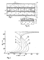
- the liquid crystal display shown in Figure 1 consists of two support plates 1 and 2 made of glass, which form a cell with a border 3.
- the border 3 consists, as usual, of an epoxy adhesive which contains spacers 4 made of glass fibers. Further spacers 4 are statistically distributed between the support plates 1 and 2 over the entire visible area of the display.
- a nematic liquid crystal 5 with positive dielectric anisotropy is filled into the cell, which contains a chiral additive.
- the inner sides of each carrier plate 1 and 2 have parallel, strip-shaped electrode layers 6 and 7 from In 2 0 3 , the direction of the strips on one carrier plate 1 being perpendicular to the direction of the strips on the other carrier plate 2. In this way, a display is formed from matrix points.
- Electrode shapes are also possible, such as the known seven-segment arrangement.
- Orientation layers 8 and 9 are applied over the electrode layers 6 and 7 and the spaces between these electrode layers.
- a Linear polarizer 10 consisting of a film is glued on.
- a linear polarizer 11 is also glued to the outside of the rear carrier plate 2 during transmission operation.
- a diffusely scattering, metallic, external reflector 12 is arranged behind this polarizer 11 (indicated by dashed lines in FIG. 1).
- the polarizer 11 can also be omitted. Although this improves the brightness, the contrast is reduced.
- FIG. 1 a shows the case when, instead of an external reflector 12, an internal reflector 13 is used, as it is e.g. is known from EP-B-060380. As the detail shows, this reflector is arranged between the electrode layer 7 and the orientation layer 9. Apart from the polarizer 11, the same elements as in FIG. 1 are otherwise present.
- FIG. 2 shows the theoretical relationship between the tilt angle of the local optical axis (ie the director) of the liquid crystal in the center of the cell and the applied operating voltage U for a typical liquid crystal.
- the angle 0 is measured with respect to the carrier plate.
- the tilt angle of the liquid crystal on the carrier plates (angle of attack) is 28 ° in both cases.
- the parameter, the total twist of the liquid crystal within the display cell runs through the values 210 ° (curve I), 240 ° (curve II), 270 ° (curve III), 300 ° (curve IV), 330 ° (curve V) and 360 ° (curve VI).
- the pitch p is chosen such that the ratio d / p is described by the following formula:
- the values 210 °, 240 °, 270 °, 300 °, 330 ° and 360 ° therefore correspond to a ratio d / p of 0.58, 0.67, 0.75, 0.91 and 1.0.
- the pitch p is defined in accordance with common usage as a parameter of the twist that is generated in the nematic liquid crystal by adding the chiral additive in the undisturbed state, and is counted positive when turning to the right and negative when turned to the left.
- the ratio of layer thickness d to pitch p of the liquid crystal is in the range from 0.50 to 0.95, preferably between 0.65 and 0.85.
- the pitch p is set by adding a certain weight fraction of a chiral additive to the nematic liquid crystal. This proportion depends on the type of liquid crystal and the chiral additive, and on the layer thickness d. It is also important that at least one of the orientation layers 8 or 9 aligns the adjacent liquid crystal molecules with an angle of incidence greater than 5 °, preferably with approximately 10 ° to 40 °. It should be noted that the orientation of the orientation layers 8 and 9 corresponds to the natural direction of rotation of the liquid crystal 5 doped with the chiral additive.
- the layer thickness d should be less than 10 ⁇ m and the total twist within the display cell should be between 180 ° and 360 °, preferably between 240 ° and 300 °. This ensures that the characteristic curve of the display, i.e. the transmission curve when the operating voltage is applied, is sufficiently steep and the range of bistable behavior is narrowed in such a way that with operating voltages outside this range using the usual multiplex method (see e.g. IEEE Trans. El. Dev ., Vol. ED-21, No. 2, Febr. 1974, pages 146-155) can be controlled. It was found that the switching times within this range are at least a hundred times greater than outside.
- the characteristic curve of the display has a similar course to the curves in FIG. 2, except that the negative slope of the curve (curves III to VI) is to be replaced by a bistable range (hysteresis loop).
- the product of birefringence ⁇ n and thickness d of the liquid crystal in the range of 0.6 .mu.m to 1.4 .mu.m, preferably between 0.8 to 1.2 and Y m.
- the mode of operation of the liquid crystal display according to the invention in transmission can now be explained as follows:
- the light linearly polarized by the linear polarizer 10 passes through the carrier plate 1 and strikes it at an angle to the liquid crystal aligned on the orientation layer 8.
- the originally linearly polarized light is elliptically polarized, depending on the operating voltage applied.
- the direction of orientation of the orientation layer 9 and the direction of vibration of the rear linear polarizer 11 also form a certain angle.
- the orientation direction here means the projection of the local optical axis of the liquid crystal in the immediate vicinity of the orientation layer onto the level of the orientation layer.
- the direction of vibration is the direction in which the electric field vector vibrates.
- the elliptically polarized light emerging from the liquid crystal is either almost completely or hardly absorbed in the rear polarizer 11, depending on whether the main axis of the elliptically polarized light is perpendicular or parallel to the direction of oscillation of the polarizer 11.
- An optimal contrast is achieved by a suitable choice of the above-mentioned angles between the orientation layers 8 and 9 and the polarizers 10 and 11. These angles have an amount between 20 0 and 70 °, preferably between 30 ° and 60 °, the Direction of rotation can coincide with both clockwise and counter-clockwise. The clockwise direction with respect to the direction of incidence of the light and the angle with respect to the orientation direction are determined.
- the mode of operation in reflection mode is essentially the same as in transmission.
- the optimal contrast for only one polarizer 10 is determined by a suitable choice of the angle between the direction of vibration of the front linear polarizer 10 and the orientation direction of the first orientation layer 8.
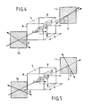
- FIGS. 4 and 5 show in an exploded, perspective representation the arrangement of the polarizers 10 and 11, the orientation layers 8 and 9 and the liquid crystal 5 located between the orientation layers, the twisting of which (P is illustrated by a chain of schematic liquid crystal molecules in the form of rectangular platelets. Carrier plates, borders and possible reflectors have been left out for the sake of clarity.
- the elements of the cell are arranged along an axis of the cell pointing in the direction of the incident light.
- the directions of oscillation of the polarizers 10 and 11 and the directions of orientation of the orientation layers 8 and 9 are each indicated by solid arrows which lie in the corresponding planes perpendicular to the axis of the cell mentioned.
- a right-handed system is defined by this directional axis or the direction of incidence of the light, in which the angles occurring are counted clockwise positive, otherwise negative.
- the liquid crystal molecules shown by way of example form a left-hand screw which, starting from the front orientation layer 8, has a twist P of -270 °.
- the directions of oscillation of the polarizers 10 and 11 are rotated out of the orientation directions of the orientation layers 8 and 9 shown in dashed lines in the polarizer planes by an angle ⁇ or ⁇ .
- the angles ⁇ and ⁇ are each positive.
- ⁇ is positive, but ⁇ is negative.
- the following angle specifications always relate to the determination made in FIGS. 4 and 5.
- the invention has proven itself in a reflective display cell with a layer thickness d of 7.6 ⁇ m and a total twist ⁇ of the liquid crystal of -270 °.
- the ratio d / p is -0.75.
- the first orientation layer 8 is produced by oblique vapor deposition with SiO at an angle of 5 ° to the plane of the plate, so that the neighboring liquid crystal molecules are oriented such that the angle of incidence between the local optical axis of the liquid crystal on the orientation layer and the projection of this optical axis onto the Plate level, ie the direction of orientation, is 28 °.
- the direction of vibration of the front polarizer 10 and the orientation direction of the orientation layer 8 form an angle of approximately 30 °.
- the second orientation layer 9 is a rubbed polymer layer and gives an angle of attack of 1 °.
- the liquid crystal 5 consists of the nematic mixture ZLI-1840 from Merck, FRG, and 2.05 percent by weight of the chiral additive cholesteryl nonanoate. This liquid crystal has one positive dielectric anisotropy of +12.2 and a birefringence of 0.15.
- the temperature range extends from 258 K to 363 K, the viscosity is 1.18 ⁇ 10 -4 m '/ s at 273 K and 3.1 ⁇ 10- 3 m' / s at 293 K.
- This display cell is used to control 96 lines using the usual multiplex method.
- the operating voltages are 1.90 V for the non-activated state (dark) and 2.10 V for the activated state (light).
- the display is completely achromatic in the light state and deep blue in the dark state. If an additional optical delay plate, e.g. a ⁇ / 4 plate, used between the front linear polarizer 10 and the front support plate 1, the color of the display can be changed accordingly. It has an excellent viewing angle regardless of the direction of illumination.
- the display's on and off times are 0.4 s at 296 K.
- V s and V ns are the usual selected and non-selected drive voltages after the pre called article IEEE Trans. El. Dev.
- the ratio V s / V ns is then 1.106 with a multiplex g rad of 100: 1.
- condition (3) the dark purple display (blue mode) is obtained (curve B from FIG. 3) in the non-selected state.
- the twist was 270 °, the angle of 24 °, the film thickness of 6.3 microns and the birefringence An was 0, 15 °.
- the maximum contrast ratio CR is significantly lower at about 6.5: 1.
- ⁇ is approximately 38 ° and is therefore in an unexpected angular range.
- the invention enables a highly multiplexable, high-contrast and fast liquid crystal display with a large viewing angle range, which can also be produced using the technology which has been tried and tested in conventional TN (twisted nematic) cells.
Landscapes
- Physics & Mathematics (AREA)
- Nonlinear Science (AREA)
- General Physics & Mathematics (AREA)
- Optics & Photonics (AREA)
- Chemical & Material Sciences (AREA)
- Crystallography & Structural Chemistry (AREA)
- Liquid Crystal (AREA)
- Liquid Crystal Substances (AREA)
Abstract
Description
- Die Erfindung betrifft eine Flüssigkristallanzeige nach dem Oberbegriff des Patentanspruchs 1. Eine solche Anzeige ist z.B. bekannt aus J. Appl. Phys., Jahrgang 53, Band 12 (Dezember 1982), Seiten 8599 bis 8606.
- Die dort beschriebene Flüssigkristallanzeige funktioniert nach dem Bistabilitätseffekt und besteht aus einer Zelle mit zwei planparallelen Glasplatten, die mittels Abstandshalter in der Umrandung der Zelle beabstandet werden und nur auf zwei Seiten verklebt sind. Der Abstand zwischen den Glasplatten beträgt etwa 15 µm. Es wird ausdrücklich erwähnt, dass Staubpartikel in der Zelle und Störungen an den Oberflächen der Glasplatten ungünstig sind für eine solche Anzeige. Diese Phänomene beschleunigen das Verschwinden des Angezeigten, welches bei den angegebenen Ansteuermethoden unvermeidbar ist. Deshalb muss die Anzeige ständig aufgefrischt werden. Die Anzeigezelle befindet sich zwischen zwei gekreuzten Polarisatoren. Auf den Innenseiten der Glasplatten sind Elektrodenschichten und darüber Orientierungsschichten vorgesehen. Die letzteren sind erzeugt durch schräges Aufdampfen von Si0 unter einem Winkel von 5° mit der Plattenebene. Dadurch werden die benachbarten Flüssigkristallmoleküle mit einem Anstellwinkel von 55° mit der Plattennormale ausgerichtet. Die in der Plattenebene liegenden Orientierungsrichtungen der Orientierungsschichten stehen entweder parallel oder senkrecht zu der Schwingungsrichtung der Polarisatoren. Als Flüssigkristall ist die Cyano-Biphenyl Mischung E7 mit dem chiralen Zusatz Cholesteryl Nonanoat in die Zelle eingefüllt. Die interne Schraubendrehung des Flüssigkristalls beträgt 360°, das Verhältnis zwischen Schichtdicke und Ganghöhe 0,983. Für dieses Verhältnis wird ein Bereich von 0,95 bis 1,10 als sinnvoll erachtet. Unterhalb 0,95 sind die Schaltzeiten sehr lang, so dass dieser Bereich für eine solche Anzeige auszuschliessen ist. Zudem wird ausdrücklich ein einwandfreies bistabiles Verhalten der Anzeige angestrebt, für welches Schichtdicke und Ganghöhe etwa gleich sein sollten. Die Anzeige wird entweder nach dem 3 : 1 - Ansteuerschema oder nach dem 2 : 1 - Ansteuerschema betrieben, bei denen zeilenweise geschrieben wird. Da die Anzeige ständig aufgefrischt werden muss, können nur wenige Zeilen geschrieben werden. Das bedeutet, dass der Multiplexgrad niedrig ist und eine grosse Punktmatrixanzeige gemäss dem obigen Artikel nicht realisierbar ist.
- Die Erfindung, wie sie in den Patentansprüchen gekennzeichnet ist, löst die Aufgabe, eine Flüssigkristallanzeige nach dem Bistabilitätseffekt anzugeben, die eine stete Anzeige ohne Auffrischung ermöglicht, nach dem üblichen Multiplexverfahren mit einem hohen Multiplexgrad ansteuerbar ist und einen grossen Sichtwinkelbereich bei hohem Kontrast aufweist.
- Die Erfindung beruht auf der Erkenntnis, dass bei einer Anzeige nach dem Bistabilitätseffekt durch eine Verringerung der gesamten Verdrillung innerhalb der Anzeigezelle und gleichzeitig eine Verringerung des Verhältnisses zwischen Schichtdicke und Ganghöhe des Flüssigkristalls der Spannungsbereich, in dem das bistabile Verhalten der Anzeige auftritt, derart eingeengt wird, dass mit Ansteuerspannungen nach dem üblichen Multiplexverfahren susserhalb dieses Bereiches ein hoher Multiplexgrad erreicht wird. Dabei soll die gesamte Verdrillung des Flüssigkristalls innerhalb der Anzeigezelle dem Betrege nach zwischen 180° und 360° liegen. Ferner soll der Abstand der Trägerplatten kleiner als 10 µm sein, wodurch speziell die Schaltzeiten erheblich verkürzt werden können.
- Durch die Erfindung wird nunmehr eine Flüssigkristallanzeige nach dem Bistabilitätseffekt ermöglicht, die für grosse Punktmatrixanzeigen besonders geeignet ist, schnelle Schaltzeiten aufweist und einen sehr grossen Blickwinkelbereich bei hohem Kontrast besitzt. Weitere Vorteile der Erfindung ergeben sich aus dem nachstehenden Ausführungsbeispiel, das anhand der Zeichnungen näher erläutert wird. Dabei zeigt:
- Fig. 1 einen Querschnitt einer erfindungsgemässen Flüssigkristallanzeige,
- Fig. la einen Ausschnitt einer erfindungsgemässen Flüssigkristallanzeige mit internem Reflektor,
- Fig. 2 Kurven mit der gesamten Verdrillung des Flüssigkristalls als Parameter, in einem Diagramm mit der Betriebsspannung U und dem Verkippungswinkel θ in der Mitte der Anzeigezelle als Variablen,
- Fig. 3 Kontrastkurven für eine reflexive Anzeigezelle mit zwei Polarisatoren,
- Fig. 4 die schematische Anordnung der Polarisatoren in einer Flüssigkristallanzeige nach Fig. 1 für ein erstes Betriebsverfahren (gelber Mode),
- Fig. 5 eine Fig. 4 entsprechende Anordnung für ein zweites Betriebsverfahren (blauer Mode),
- Fig. 6 das in einer Anordnung nach Fig. 4 gemessene Kontrastverhältnis CR in Abhängigkeit von der Polarisatorstellung,
- Fig. 7 die Fig.6 entsprechenden Ergebnisse für eine Anordnung nach Fig. 5,
- Fig. 8 die berechneten Linien konstanten Kontrastverhältnisses in Abhängigkeit von der Polarisatoreinstellung und dem Produkt Δn x d für eine Anordnung mit einem Polarisator und einem Reflektor,
- Fig. 9 die Fig. 8 entsprechenden Linien für eine Anordnung nach Fig. 5, und
- Fig. 10 die Fig. 8 entsprechenden Linien für eine Anordnung nach Fig. 4.
- Die in Figur 1 dargestellte Flüssigkristallanzeige besteht aus zwei Trägerplatten 1 und 2 aus Glas, die mit einer Umrandung 3 eine Zelle bilden. Die Umrandung 3 besteht, wie üblich, aus einem Epoxy-Klebstoff, der Abstandshalter 4 aus Glasfasern enthält. Weitere Abstandshalter 4 sind zwischen den Trägerplatten 1 und 2 über die ganze Sichtfläche der Anzeige statistisch verteilt. In die Zelle ist ein nematischer Flüssigkristall 5 mit positiver dielektrischer Anisotropie eingefüllt, der einen chiralen Zusatz enthält. Die Innenseiten jeder Trägerplatte 1 und 2 besitzen parallele, streifenförmige Elektrodenschichten 6 und 7 aus In203, wobei die Richtung der Streifen auf der einen Trägerplatte 1 senkrecht zur Richtung der Streifen auf der andern Trägerplatte 2 verläuft. Auf diese Art wird eine Anzeige aus Matrixpunkten gebildet. Jedoch sind auch andere Elektrodenformen möglich, wie z.B. die bekannte Siebensegment-Anordnung. Ueber die Elektrodenschichten 6 und 7 und die Zwischenräume zwischen diesen Elektrodenschichten sind Orientierungsschichten 8 und 9 aufgetragen. Auf der Aussenseite der vorderen Trägerplatte 1 ist ein aus einer Folie bestehender Linearpolarisator 10 aufgeklebt. Auf der aussenseite der hinteren Trägerplatte 2 ist bei Transmissionsbetrieb ebenfalls ein Linearpolarisator 11 aufgeklebt. Für Reflexionsbetrieb ist hinter diesem Polarisator 11 ein diffus streuender, metallischer, externer Reflektor 12 angeordnet (strichliert angedeutet in Fig. 1). Ein solcher ist z.B. bekannt aus CH-B-618018. Der Polarisator 11 kann jedoch auch weggelassen werden. Dadurch wird zwar die Helligkeit verbessert, der Kontrast jedoch geringer.
- In Figur la ist der Fall dargestellt, wenn statt eines externen Reflektors 12 ein interner Reflektor 13 verwendet wird, wie er z.B. aus EP-B-060380 bekannt ist. Wie der Ausschnitt zeigt, ist dieser Reflektor zwischen der Elektrodenschicht 7 und der Orientierungsschicht 9 angeordnet. Ansonsten sind ausser dem Polarisator 11 die gleichen Elemente wie in Figur 1 vorhanden.
- Figur 2 stellt für einen typischen Flüssigkristall den theoretischen Zusammenhang zwischen dem Verkippungswinkel der lokalen optischen Achse (d.h. dem Direktor) des Flüssigkristalls in der Mitte der Zelle und der angelegten Betriebsspannung U dar. Der Winkel 0 wird in bezug zur Trägerplatte gemessen. Der Verkippungswinkel des Flüssigkristalls an den Trägerplatten (Anstellwinkel) beträgt in beiden Fällen 28°. Der Parameter, die gesamte Verdrillung des Flüssigkristalls innerhalb der Anzeigezelle, durchläuft dabei die Werte 210° (Kurve I), 240° (Kurve II), 270° (Kurve III), 300° (Kurve IV), 330° (Kurve V) und 360° (Kurve VI). Bei einer bestimmten Schichtdicke d des Flüssigkristalls ist die Ganghöhe p so gewählt, dass das Verhältnis d/p durch die folgende Formel beschrieben wird:

- Dies gewährleistet, dass der Verdrillungszustand der Flüssigkristallschicht stabil ist und nicht um zusätzlich + 180° verdreht, und dass keine optischen Störungen in der Anzeige auftreten. Die Werte 210°, 240°, 270°, 300°, 330° und 360° entsprechen daher einem Verhältnis d/p von 0,58, 0,67, 0,75, 0,91 und 1,0. Die Ganghöhe p ist dabei gemäss dem üblichen Sprachgebrauch definiert als Kenngrösse der Verdrillung, die in dem nematischen Flüssigkristall durch Zugabe des chiralen Zusatzes im ungestörten Zustand erzeugt wird, und wird bei Rechtsdrehung positiv, bei Linksdrehung dagegen negativ gezählt..
- Erfindungswesentlich ist, dass das Verhältnis von Schichtdicke d zu Ganghöhe p des Flüssigkristalls dem Betrage nach im Bereich von 0,50 bis 0,95 liegt, bevorzugt zwischen 0,65 und 0,85. Die Ganghöhe p wird dadurch eingestellt, dass dem nematischen Flüssigkristall ein bestimmter Gewichtsanteil eines chiralen Zusatzes beigemischt wird. Dieser Anteil ist abhängig von der Art des Flüssigkristalls und des chiralen Zusatzes, und von der Schichtdicke d. Ferner ist es wichtig, dass mindestens eine der Orientierungsschichten 8 oder 9 die benachbarten Flüssigkristallmoleküle mit einem Anstellwinkel grösser als 5° ausrichtet, bevorzugt mit etwa 10° bis 40°. Dabei ist zu beachten, dass die Ausrichtung der Orientierungsschichten 8 und 9 mit dem natürlichen Drehsinn des mit dem chiralen Zusatz dotierten Flüssigkristalls 5 übereinstimmt. Weiterhin soll die Schichtdicke d kleiner als 10 um und die gesamte Verdrillung innerhalb der Anzeigezelle dem Betrage nach zwischen 180° und 360° liegen, bevorzugt zwischen 240° und 300°. Dadurch wird gewährleistet, dass die Kennlinie der Anzeige, d.h. die Transmissionskurve bei angelegter Betriebsspannung, ausreichend steil ist und der Bereich des bistabilen Verhaltens derart eingeengt ist, dass mit Betriebsspannungen ausserhalb dieses Bereiches nach dem üblichen Multiplexverfahren (vgl. z.B. IEEE Trans. El. Dev., Vol. ED-21, No. 2, Febr. 1974, Seiten 146-155) angesteuert werden kann. Es wurde gefunden, dass innerhalb dieses Bereiches die Schaltzeiten mindestens hundert mal grösser sind als ausserhalb. Die Kennlinie der Anzeige hat einen ähnlichen Verlauf wie die Kurven in Fig. 2, ausser dass die negative Steigung der Kurve (Kurven III bis VI) durch einen bistabilen Bereich (Hystereseschleife) ersetzt werden soll.
- Ein anderer wichtiger Punkt ist, dass das Produkt von Doppelbrechung Δ n und Schichtdicke d des Flüssigkristalls in dem Bereich von 0,6 µm bis 1,4 µm liegt, bevorzugt zwischen 0,8 um und 1,2 Ym.
- Die Funktionsweise der erfindungsgemässen Flüssigkristallanzeige in Transmission lässt sich nun wie folgt erklären: Das durch den Linearpolarisator 10 linear polarisierte Licht durchsetzt die Trägerplatte 1 und trifft unter einem Winkel zu dem an der Orientierungsschicht 8 ausgerichteten Flüssigkristall auf. Wegen der gesamten Verdrillung und der doppelbrechenden Eigenschaften des Flüssigkristalls wird das ursprünglich linear polarisierte Licht elliptisch polarisiert, und zwar unterschiedlich je nach angelegter Betriebsspannung. Die Orientierungsrichtung der Orientierungsschicht 9 und die Schwingungsrichtung des hinteren Linearpolarisators 11 bilden ebenfalls einen bestimmten Winkel. Unter der Orientierungsrichtung wird hierbei die Projektion der lokalen optischen Achse des Flüssigkristalls in unmittelbarer Nähe der Orientierungsschicht auf die Ebene der Orientierungsschicht verstanden. Die Schwingungsrichtung ist diejenige Richtung, in welcher der elektrische Feldvektor schwingt. Das aus dem Flüssigkristall austretende, elliptisch polarisierte Licht wird im hinteren Polarisator 11 entweder fast vollständig oder kaum absorbiert, je nach dem ob die Hauptachse des elliptisch polarisierten Licht senkrecht oder parallel zur Schwingungsrichtung des Polarisators 11 steht. Durch geeignete Wahl der obengenannten Winkel zwischen den Orientierungsschichten 8 und 9 und den Polarisatoren 10 und 11 wird ein optimaler Kontrast erreicht. Diese Winkel haben einen Betrag zwischen 200 und 70°, bevorzugt zwischen 30° und 60°, wobei der Drehsinn sowohl mit dem Uhrzeigersinn als auch mit dem Gegen-Uhrzeigersinn zusammenfallen kann. Dabei ist der Uhrzeigersinn in bezug auf die Einfallsrichtung des Lichts und der Winkel in bezug auf die Orientierungsrichtung bestimmt.
- Im Reflexionsbetrieb ist die Wirkungsweise im wesentlichen gleich wie bei der Transmission. Insbesondere wird der optimale Kontrast bei nur einem Polarisator 10 durch geeignete Wahl des Winkels zwischen der Schwingungsrichtung des vorderen Linearpolarisators 10 und der Orientierungsrichtung der ersten Orientierungsschicht 8 bestimmt.
- Da die erwähnten Winkel zwischen den Schwingungsrichtungen der Polarisatoren 10, 11 und den Orientierungsrichtungen der Orientierungsschichten 8, 9 für das Erreichen eines optimalen Kontrastverhältnisses CR eine wesentliche Rolle spielen, werden diese Winkel durch die schematischen Anordnungen in den Figuren 4 und 5 in ihrer Zählweise noch einmal näher erläutert.
- Die Figuren 4 und 5 zeigen in explosionsartiger, perspektivischer Darstellung die Anordnung der Polarisatoren 10 und 11, der Orientierungsschichten 8 und 9 sowie den zwischen den Orientierungsschichten befindlichen Flüssigkristall 5, dessen Uerdrillung (P durch eine Kette von schematisierten Flüssigkristallmolekülen in Form rechteckiger Plättchen veranschaulicht wird. Trägerplatten, Umrandung und mögliche Reflektoren sind der Uebersichtlichkeit halber weggelassen.
- Die Elemente der Zelle sind entlang einer Achse der Zelle angeordnet, die in Richtung des einfallenden Lichts zeigt. Die Schwingungsrichtungen der Polarisatoren 10 und 11 sowie die Orientierungsrichtungen der Orientierungsschichten 8 und 9 sind jeweils durch ausgezogene Pfeile angedeutet, die in den entsprechenden Ebenen senkrecht zur genannten Achse der Zelle liegen.
- Durch diese gerichtete Achse bzw. die Einfallsrichtung des Lichts wird ein rechtshändiges System definiert, in dem die auftretenden Winkel im Uhrzeigersinn positiv, andernfalls negativ gezählt werden. In den Fällen der Figuren 4 und 5 bilden daher die beispielshaft eingezeichneten Flüssigkristallmoleküle eine Linksschraube, die, von der vorderen Orientierungsschicht 8 ausgehend, eine Verdrillung P von -270° aufweist.
- Die Schwingungsrichtungen der Polarisatoren 10 und 11 sind aus den in die Polarisatorebenen gestrichelt eingezeichneten Orientierungsrichtungen der Orientierungsschichten 8 und 9 um einen Winkel β bzw. δ herausgedreht. In der Anordnung nach Fig. 4 sind die Winkel β und δ jeweils positiv. In der Anordnung nach Fig. 5 ist nur β positiv, δ dagegen negativ. Die nachfolgenden Winkelangaben beziehen sich stets auf die in. Fig. 4 und 5 getroffene Festlegung.
- Die Erfindung hat sich bewährt bei einer reflektiven Anzeigezelle mit einer Schichtdicke d von 7,6 um und einer gesamten Verdrillung Φ des Flüssigkristalls von -270°. Das Verhältnis d/p beträgt hier -0,75. Die erste Orientierungsschicht 8 ist durch schräges Aufdampfen mit SiO unter einem Winkel von 5° zur Plattenebene hergestellt, so dass die benachbarten Flüssigkristallmoleküle derart ausgerichtet sind, dass der Anstellwinkel zwischen der lokalen optischen Achse des Flüssigkristalls an der Orientierungsschicht und der Projektion dieser optischen Achse auf die Plattenebene, d.h. der Orientierungsrichtung, 28° beträgt. Die Schwingungsrichtung des vorderen Polarisators 10 und die Orientierungsrichtung der Orientierungsschicht 8 bilden einen Winkel von etwa 30°. Die zweite Orientierungsschicht 9 ist eine geriebene Polymerschicht und ergibt einen Anstellwinkel von 1°. Jedoch ist eine ähnliche Orientierungsschicht wie die erste ebenfalls möglich. Der Flüssigkristall 5 besteht aus der nematischen Mischung ZLI-1840 der Firma Merck, BRD, und 2,05 Gewichtsprozent des chiralen Zusatzes Cholesteryl Nonanoat. Dieser Flüssigkristall besitzt eine positive dielektrische Anisotropie von +12,2 und eine Doppelbrechung von 0,15. Der Temperaturbereich erstreckt sich von 258 K bis 363 K, die Viskosität beträgt 1,18 · 10-4 m'/s bei 273 K und 3,1 · 10-3 m'/s bei 293 K.
- Mit dieser Anzeigezelle werden 96 Zeilen nach dem üblichen Multiplexverfahren angesteuert. Die Betriebsspannungen sind 1,90 V für den nicht-angesteuerten Zustand (dunkel) und 2,10 V für den angesteuerten Zustand (hell). Die Anzeige ist im hellen Zustand völlig achromatisch, im dunklen Zustand tief blau. Wenn zusätzlich eine optische Verzögerungsplatte, wie z.B. eine λ/4-Platte, zwischen dem vorderen Linearpolarisator 10 und der vorderen Trägerplatte 1 verwendet wird, kann die Farbe der Anzeige entsprechend geändert werden. Sie besitzt einen hervorragenden Blickwinkelbereich unabhängig von der Beleuchtungsrichtung. Die Ein- und Ausschaltzeiten der Anzeige betragen 0,4 s bei 296 K.
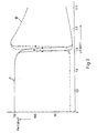
- Eine andere besonders bevorzugte Ausführungsform der Erfindung besteht aus einer reflektiven Anzeigezelle mit einer 0,7 mm dicken Trägerplatte 1 und einer 0,5 mm dicken Trägerplatte 2. Die Schichtdicke d beträgt 6,5 µm. Bei dieser Anzeigezelle sind ein vorderer Polarisator 10, ein hinterer Polarisator 11 und ein externer Reflektor 12 vorgesehen. Die beiden Orientierungsschichten 8 und 9 sind durch schräges Aufdampfen mit Si0 unter einem Winkel von 5° zur Plattenebene hergestellt und richten die benachbarten Flüssigkristallmoleküle derart aus, dass die optische Achse des Flüssigkristalls einen Anstellwinkel von 28° zur Plattenebene bildet. Die Orientierungsschichten 8 und 9 sind so angeordnet, dass die gesamte Verdrillung f eine linkshändige Drehung von -250° macht. Als Flüssigkristall 5 ist die nematische Mischung ZLI-1840 mit einem chiralen Zusatz von 2,56 Gewichtsprozent Cholesteryl Nonanoat in die Zelle eingefüllt. Die Doppelbrechung Δn von ZLI-1840 beträgt 0,15, so dass das Produkt Δn · d = 0,975 ist. Der Winkel β zwischen der Schwingungsrichtung des vorderen Linearpolarisators 10 und der Orientierungsrichtung der zugehörigan Orientierungsschicht 8 und der Winkel zwiechen der Schwingungsrichtung des hinteren Linearpolarisators 11 und der Orientierungsrichtung der zugehörigen Orientierungsschicht 9 betragen 45°. In Fig. 3 sind die Kontrastkurven angegeben für den Fall, dass beide Winkel 45° oder beide winkel -45° sind (Kurve A), und für den Fall, dass der eine Winkel 45° und der andere Winkel -45° ist, oder umgekehrt (Kurvs B). Die Abszisse gibt dabei die angelegte Spannung U in Volt an, die Ordinate die Helligkeit der Anzeige in willkürlichen Einheiten. Im ersten Fall (Kurve A) erhält man im nicht-angewählten Zustand eine hell-gelbe Anzeige, im angewählten Zustand eine schwarze Anzeige. Diesem Fall entspricht die Anordnung nach Fig. 4, in der die beiden Winkel β und δ gleichsinnig positiv oder negativ gewählt werden (gelber Mode). Im zweiten Fall (Kurve B) erhält man eine dunkel-violette Anzeige im nicht-angewählten Zustand, eine helle Anzeige im angewählten Zustand. Diesem Fall entspricht die Anordnung nach Fig. 5, in der die Winkel β und δ gegensinnig gewählt werden (blauer Mode). Die Messungen wurden ausgeführt bei senkrecht einfallendem Licht mit einem Photometer der Firma Tektronix, Modell J 6523. Dieses Photometer berücksichtigt die spektrale Empfindlichkeit des menschlichen Auges. Die Rampe beträgt 30 mV/sec. Die gemessenen Kontrastverhältnisse bei einem Multiplexgrad von 100 : 1 sind wie folgt:
- Kurve A Vs = 1.580 V Kontrastverhältnis = 19,8 Vns = 1,429 V
- Kurve B Vs = 1,609 V Kontrastverhältnis = 11,8 Vns = 1,456 V
- Die Spannungen Vs und Vns sind die üblichen angewählten und nicht-angewählten Ansteuerspannungen nach dem vorgenannten Artikel IEEE Trans. El. Dev. Das Verhältnis Vs/Vns ist dann 1,106 bei einem Multiplexgrad von 100 : 1.
- Bei der Verwendung von zwei Polarisatoren mit den Winkeln β und δ relativ zu den Orientierungsrichtungen gemäss Fig. 4 und 5 wurden nun allgemeine Bedingungen gefunden, die für ein optimiertes Kontrastverhältnis CR erfüllt sein sollten. Diese Bedingungen können wie folgt beschrieben werden:


- Ist die Bedingung (2) erfüllt (z.B. β = δ = ± 45°), erhält man (Kurve A aus Fig. 3) im nicht-angewählten Zustand die hell-gelbe Anzeige (gelber Mode). Ist dagegen die Bedingung (3) erfüllt, erhält man (Kurve B aus Fig. 3) im nicht-angewählten Zustand die dunkel-violette Anzeige (blauer Mode).
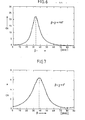
- Dass die Bedingungen (2) und (3) keine hinreichenden Bedingungen für ein optimales Kontrastverhältnis sind, geht aus den Kurven der Figuren 6 und 7 hervor, die das gemessene Kontrastverhältnis CR in Abhängigkeit vom Winkel β unter der Bedingung (2) oder (3) für eine Zelle mit zwei Linearpolarisatoren im Transmissionsbetrieb zeigen.
- Bei diesen Messungen wurde eine Flüssigkristallmischung aus 95,6 % ZLI-2392 (Merck), 2,5'% 5 811 (Merck) und 1,9 % CB 15 (BDH) verwendet. Die Verdrillung betrug -270°, der Anstellwinkel 24°, die Schichtdicke 6,3 µm und die Doppelbrechung Δn war 0,15.
- Die in Fig. 6 dargestellten Ergebnisse gelten für den gelben Mode ( β + δ ≃ ± 90°), die aus Fig. 7 entsprechend für den blauen Mode (β + δ ≃ 0°). Man erkennt, dass der Winkel beim gelben Mode für ein maximales Kontrastverhältnis CR von etwa 22 : 1 bei ungefähr 32° liegt und daher deutlich von 0° abweicht.
- Im blauen Mode (Fig. 7) iat das maximale Kontrastverhältnis CR mit etwa 6,5 : 1 deutlich geringer. Auch hier beträgt β etwa 38° und liegt damit in einem nicht erwarteten Winkelbereich.
- Die mit einem optimalen Kontrastverhältnis CR verknüpften überraschenden Werte für den Winkel β werden durch nachträgliche theoretische Berechnungen bestätigt, deren Ergebnisse in den Figuren 8 - 10 als Linien mit konstantem Kontrast- verhältnis in Abhängigkeit von dem Produkt aus Schichtdicke d und Doppelbrechung Δ n sowie vom Winkel β dargestellt sind.
- Für die Berechnungen ist ein Multiplexverhältnis von 100 : 1 vorausgesetzt, eine Schichtdicke von d = 6,2 µm, ein Brechungsindex no für den ordentlichen Strahl von 1,5, elastische Flüssigkristallkonstanten von k 33/k 22 = 2,5, k33/k11 = 1,5, ein Verhältnis der dielektrischen Konstanten von (ε∥ - ε⊥ )/ ε⊥ = 2,5, eine Verdrillung von φ = -270° sowie ein Verhältnis von Schichtdicke zu Ganghöhe von d/p = -0,75.
- Die Fig. 8 macht deutlich, dass im Falle einer im Reflexionsbetrieb mit einem Polarisator arbeitenden Zelle ein maximales Kontrastverhältnis CR von etwa 3,6 : 1 nur dann erreicht wird, wenn der Winkel β etwa 20° und Δ n x d ungefähr 1,13 µm betragen. Es wurde in diesem Fall im übrigen ein Anstellwinkel von jeweils 28° angenommen.
- Im blauen Mode einer mit zwei Polarisatoren im Reflexionsbetrieb arbeitenden Anzeigezelle (Fig. 9) erhält man entsprechende Werte von β ≃ 45° und Δ n x d ≃ 0,78 µm.
- Im zugehörigen gelben Mode (Fig. 10) ergeben sich schliesslich Werte von β ≃ 32,5° und Δ n x d ≃ 0,84 um. In den beiden letztgenannten Fällen ist dabei ein Anstellwinkel von jeweils 20° angenommen worden.
- Die theoretisch berechneten optimalen Kontrastverhältnisse von 50 und 150 liegen deutlich höher als die gemessenen, weil in der Rechnung Reflexionsbetrieb angenommen worden ist, der wegen der doppelten Ausnutzung der Polarisatoren gegenüber dem Transmissionsbetrieb ein besseres Kontrastverhältnis ergibt.
- Insgesamt ermöglicht die Erfindung eine hochmultiplexierbare, kontrastreiche und schnelle Flüssigkristallanzeige mit grossem Sichtwinkelbereich, die zudem in der bei den üblichen TN (Twisted Nematic)-Zellen erprobten Technologie hergestellt werden kann.
Claims (10)
Priority Applications (1)
| Application Number | Priority Date | Filing Date | Title |
|---|---|---|---|
| AT84107507T ATE30479T1 (de) | 1983-07-12 | 1984-06-28 | Fluessigkristallanzeige. |
Applications Claiming Priority (4)
| Application Number | Priority Date | Filing Date | Title |
|---|---|---|---|
| CH381983A CH664027A5 (de) | 1983-07-12 | 1983-07-12 | Fluessigkristallanzeige. |
| CH3819/83 | 1983-07-12 | ||
| CH583583A CH665491A5 (de) | 1983-10-28 | 1983-10-28 | Fluessigkristallanzeige. |
| CH5835/83 | 1983-10-28 |
Publications (3)
| Publication Number | Publication Date |
|---|---|
| EP0131216A2 true EP0131216A2 (de) | 1985-01-16 |
| EP0131216A3 EP0131216A3 (en) | 1985-03-13 |
| EP0131216B1 EP0131216B1 (de) | 1987-10-28 |
Family
ID=25693920
Family Applications (1)
| Application Number | Title | Priority Date | Filing Date |
|---|---|---|---|
| EP84107507A Expired EP0131216B1 (de) | 1983-07-12 | 1984-06-28 | Flüssigkristallanzeige |
Country Status (14)
| Country | Link |
|---|---|
| US (2) | US4634229A (de) |
| EP (1) | EP0131216B1 (de) |
| KR (1) | KR900008064B1 (de) |
| CA (1) | CA1242784A (de) |
| DD (1) | DD222433A5 (de) |
| DE (2) | DE3467044D1 (de) |
| FR (1) | FR2549268B1 (de) |
| GB (1) | GB2143336B (de) |
| HK (1) | HK54890A (de) |
| IN (1) | IN161652B (de) |
| NL (1) | NL8402189A (de) |
| NO (1) | NO167241C (de) |
| PH (1) | PH24617A (de) |
| SG (1) | SG20690G (de) |
Cited By (27)
| Publication number | Priority date | Publication date | Assignee | Title |
|---|---|---|---|---|
| JPS61193125A (ja) * | 1985-02-22 | 1986-08-27 | Hitachi Ltd | 液晶表示素子 |
| JPS61210324A (ja) * | 1985-03-15 | 1986-09-18 | Hitachi Ltd | 液晶表示素子 |
| JPS61231523A (ja) * | 1985-04-05 | 1986-10-15 | Hitachi Ltd | 液晶表示素子 |
| EP0235634A1 (de) * | 1986-02-27 | 1987-09-09 | Asulab S.A. | Anzeigezelle |
| WO1987005714A1 (fr) * | 1986-03-19 | 1987-09-24 | MERCK Patent Gesellschaft mit beschränkter Haftung | Element d'affichage electro-optique |
| EP0217641A3 (en) * | 1985-09-27 | 1987-12-09 | Sanyo Electric Co., Ltd. | Liquid crystal display device |
| EP0216632A3 (en) * | 1985-09-25 | 1988-11-30 | Toray Industries, Inc. | Liquid crystal electro-optical element and process for preparation thereof |
| DE3741997A1 (de) * | 1987-12-11 | 1989-06-22 | Vdo Schindling | Stn fluessigkristallzelle |
| EP0332005A1 (de) * | 1988-03-10 | 1989-09-13 | MERCK PATENT GmbH | Supertwist-Flüssigkristallanzeige |
| WO1989008692A1 (fr) * | 1988-03-10 | 1989-09-21 | MERCK Patent Gesellschaft mit beschränkter Haftung | Affichage par cristaux liquides a supertorsion |
| EP0284372A3 (en) * | 1987-03-23 | 1989-12-13 | Sharp Kabushiki Kaisha | A liquid-crystal display device |
| US4904060A (en) * | 1987-11-23 | 1990-02-27 | Asulab, S.A. | Liquid crystal display cell having a diffusely-reflective counter electrode |
| EP0312297A3 (en) * | 1987-10-13 | 1990-03-14 | Fujitsu Limited | Liquid crystal display panel |
| EP0311405A3 (en) * | 1987-10-07 | 1990-03-21 | Sharp Kabushiki Kaisha | A liquid-crystal display device |
| US4936654A (en) * | 1988-01-28 | 1990-06-26 | Sanyo Electric Co., Ltd. | Liquid crystal display device |
| US5004324A (en) * | 1986-09-12 | 1991-04-02 | Hoffmann-La Roche Inc. | Liquid crystal display |
| JPH03248121A (ja) * | 1991-02-08 | 1991-11-06 | Hitachi Ltd | 液晶表示素子 |
| JPH03249621A (ja) * | 1991-02-08 | 1991-11-07 | Hitachi Ltd | 液晶表示素子 |
| EP0431952A3 (en) * | 1989-12-08 | 1992-04-08 | Seiko Epson Corporation | Liquid crystal display device |
| EP0352101B1 (de) * | 1988-07-19 | 1994-09-14 | Sharp Kabushiki Kaisha | Doppelschicht-Flüssigkristall-Anzeigevorrichtung |
| JPH0850271A (ja) * | 1995-07-10 | 1996-02-20 | Hitachi Ltd | 液晶表示素子 |
| EP0341702B1 (de) * | 1988-05-11 | 1996-10-16 | Kabushiki Kaisha Toshiba | Flüssigkristall-Anzeigevorrichtung |
| EP0772074A1 (de) | 1995-11-01 | 1997-05-07 | E.I. Du Pont De Nemours And Company | Polyimidfilm aus Pyromellitsäuredianhydrid und Bis-(4-aminophenoxy)Aromat als Orientierungsschicht für Flüssigkristallanzeigen |
| EP0559137B1 (de) * | 1992-03-03 | 1998-06-03 | Matsushita Electric Industrial Co., Ltd. | Verdrillt-nematische Flüssigkristall-Anzeigevorrichtung mit aktiver Matrix |
| US5876626A (en) * | 1988-10-20 | 1999-03-02 | Merck Patent Gesellschaft Mit Beschrankter Haftung | Supertwist liquid crystal display |
| KR100743725B1 (ko) * | 2000-09-21 | 2007-07-30 | 메르크 파텐트 게엠베하 | 액정 혼합물 |
| CN101441365B (zh) * | 2005-04-18 | 2010-11-03 | 胜华科技股份有限公司 | 一种双稳态液晶显示装置 |
Families Citing this family (69)
| Publication number | Priority date | Publication date | Assignee | Title |
|---|---|---|---|---|
| US4596446B2 (en) * | 1982-06-29 | 1997-03-18 | Secr Defence Brit | Liquid crystal devices with particular cholestric pitch-cell thickness ratio |
| JPS6050511A (ja) * | 1983-08-31 | 1985-03-20 | Hitachi Ltd | 液晶表示素子 |
| US5215677A (en) * | 1985-09-27 | 1993-06-01 | Sanyo Electric Co., Ltd. | Liquid crystal display device |
| US5044735A (en) * | 1985-11-29 | 1991-09-03 | Konishiroku Photo Industry Co., Ltd. | Liquid crystal display device for providing sufficiently high contrast ratio and excellent response time |
| JPS62194224A (ja) * | 1986-02-20 | 1987-08-26 | Sharp Corp | ツイステツド・ネマチツク型液晶表示素子 |
| US4726659A (en) * | 1986-02-24 | 1988-02-23 | Rca Corporation | Display device having different alignment layers |
| US5188758A (en) * | 1986-03-19 | 1993-02-23 | Merck Patent Gesellschaft Mit Beschraenkter Haftung | Electrooptical display element using a supertwist liquid crystal having specified elastic constants |
| EP0246842B1 (de) * | 1986-05-19 | 1998-09-23 | Seiko Epson Corporation | Flüssigkristall-Anzeigevorrichtung |
| US4776674A (en) * | 1986-06-25 | 1988-10-11 | American Telephone And Telegraph Company, At&T Bell Laboratories | Liquid crystal device with chemically-induced high-tilt alignment coating |
| US4779958A (en) * | 1986-06-28 | 1988-10-25 | Kabushiki Kaisha Toshiba | Liquid crystal device having different natural and induced twists |
| US4818074A (en) * | 1986-09-03 | 1989-04-04 | Ricoh Company, Ltd. | Projection device for irradiating a light to a display device and optically magnifying and projecting a reflection light therefrom |
| JP2676508B2 (ja) * | 1986-09-12 | 1997-11-17 | コニカ株式会社 | 液晶表示装置 |
| JPS63167331A (ja) * | 1986-12-29 | 1988-07-11 | Sharp Corp | ツイステツド・ネマチツク型液晶表示素子 |
| JPS63220221A (ja) * | 1987-03-10 | 1988-09-13 | Sharp Corp | カラ−液晶表示素子 |
| FR2613566B1 (fr) * | 1987-04-06 | 1989-06-09 | Commissariat Energie Atomique | Ecran a matrice active pour affichage en couleur d'images de television, systeme de commande et procede de fabrication dudit ecran |
| GB2204174B (en) * | 1987-04-23 | 1991-03-13 | Seiko Instr Inc | Electro-optical modulator |
| NL8801164A (nl) * | 1987-06-10 | 1989-01-02 | Philips Nv | Weergeefinrichting voor gebruik in reflectie. |
| JPS6421416A (en) * | 1987-07-17 | 1989-01-24 | Hitachi Ltd | Liquid crystal display element |
| KR0134974B1 (ko) * | 1987-07-29 | 1998-04-22 | 미다 가쓰시게 | 트위스트 나선구조를 가지는 네마틱 액정표시장치 |
| US5044733A (en) * | 1987-08-19 | 1991-09-03 | Ricoh Company, Ltd. | Super twisted nematic liquid crystal display device having the standard deviation of the spherical grains being not more than 3% and the dispersion quantity of the spherical grains being 100-200 grains/mm2 |
| JPH01120527A (ja) * | 1987-11-04 | 1989-05-12 | Sharp Corp | 液晶表示装置 |
| JPH07117664B2 (ja) * | 1987-12-03 | 1995-12-18 | シャープ株式会社 | 液晶表示装置 |
| EP0393191B1 (de) * | 1988-01-28 | 1995-12-20 | Sanyo Electric Co., Ltd. | Flüssigkristallanzeigeanordnung |
| JP2621385B2 (ja) * | 1988-07-06 | 1997-06-18 | セイコーエプソン株式会社 | 電気光学装置 |
| EP0377757B1 (de) * | 1988-07-14 | 1997-01-08 | Seiko Epson Corporation | Reflektive elektrooptische flüssigkristallvorrichtung und projektionsanzeigevorrichtung unter verwendung derselben |
| US4944578A (en) * | 1988-07-21 | 1990-07-31 | Telex Communications | Color graphic imager utilizing a liquid crystal display |
| US5302946A (en) * | 1988-07-21 | 1994-04-12 | Leonid Shapiro | Stacked display panel construction and method of making same |
| US5153568A (en) * | 1988-07-21 | 1992-10-06 | Proxima Corporation | Liquid crystal display panel system and method of using same |
| US5089810A (en) * | 1990-04-09 | 1992-02-18 | Computer Accessories Corporation | Stacked display panel construction and method of making same |
| US5058998A (en) * | 1988-09-16 | 1991-10-22 | Casio Computer Co., Ltd. | Liquid crystal display devide with a twisted alignment state |
| JPH0642125B2 (ja) * | 1988-10-04 | 1994-06-01 | シャープ株式会社 | プロジェクション装置 |
| DE3835804B4 (de) * | 1988-10-20 | 2006-12-28 | Merck Patent Gmbh | Nematische Flüssigkristallmischung |
| DE3843767A1 (de) * | 1988-12-24 | 1990-07-05 | Nokia Unterhaltungselektronik | Fluessigkristalldisplay fuer schwarz/weiss-darstellung |
| USRE36654E (en) * | 1989-03-28 | 2000-04-11 | In Focus Systems, Inc. | Stacked LCD color display |
| US4917465A (en) * | 1989-03-28 | 1990-04-17 | In Focus Systems, Inc. | Color display system |
| US5050965A (en) * | 1989-09-01 | 1991-09-24 | In Focus Systems, Inc. | Color display using supertwisted nematic liquid crystal material |
| JP2784205B2 (ja) * | 1989-04-14 | 1998-08-06 | コニカ株式会社 | 透過型液晶表示装置 |
| US5229031A (en) * | 1989-05-17 | 1993-07-20 | Seiko Epson Corporation | Liquid crystal display device |
| US4991924A (en) * | 1989-05-19 | 1991-02-12 | Cornell Research Foundation, Inc. | Optical switches using cholesteric or chiral nematic liquid crystals and method of using same |
| DE3923064B4 (de) * | 1989-07-13 | 2004-08-05 | Merck Patent Gmbh | Flüssigkristallmischung und sie enthaltende Supertwist-Flüssigkristallanzeige |
| JPH03122615A (ja) * | 1989-10-06 | 1991-05-24 | Toshiba Corp | 液晶表示装置 |
| US6392689B1 (en) * | 1991-02-21 | 2002-05-21 | Eugene Dolgoff | System for displaying moving images pseudostereoscopically |
| US5184156A (en) * | 1991-11-12 | 1993-02-02 | Reliant Laser Corporation | Glasses with color-switchable, multi-layered lenses |
| US5696570A (en) * | 1992-04-16 | 1997-12-09 | Merck Patent Gesellschaft Mit Beschrankter Haftung | TN cell having improved display of grey shades |
| US5327269A (en) * | 1992-05-13 | 1994-07-05 | Standish Industries, Inc. | Fast switching 270° twisted nematic liquid crystal device and eyewear incorporating the device |
| US6693696B1 (en) * | 1992-06-30 | 2004-02-17 | Semiconductor Energy Laboratory Co., Ltd. | Electro-optical device |
| JP3634390B2 (ja) * | 1992-07-16 | 2005-03-30 | セイコーエプソン株式会社 | 液晶電気光学素子 |
| JPH0784252A (ja) * | 1993-09-16 | 1995-03-31 | Sharp Corp | 液晶表示装置 |
| US5432624A (en) * | 1993-12-03 | 1995-07-11 | Reliant Technologies, Inc. | Optical display unit in which light passes a first cell, reflects, then passes a second cell |
| JP2927662B2 (ja) * | 1993-12-24 | 1999-07-28 | シャープ株式会社 | 液晶表示装置 |
| US5574583A (en) * | 1994-08-02 | 1996-11-12 | Hyundai Electronics Industries Co. Ltd. | Liquid crystal display device having a compensation layer and method for fabricating the same |
| US6258443B1 (en) | 1994-09-28 | 2001-07-10 | Reflexite Corporation | Textured retroreflective prism structures and molds for forming same |
| JPH08166605A (ja) * | 1994-10-14 | 1996-06-25 | Sharp Corp | 液晶表示装置 |
| US5986732A (en) * | 1995-01-23 | 1999-11-16 | Asahi Glass Company Ltd. | Color liquid crystal display apparatus |
| JP3577719B2 (ja) | 1995-05-17 | 2004-10-13 | セイコーエプソン株式会社 | 液晶表示装置及びその駆動方法並びにそれに用いる駆動回路 |
| US6094252A (en) * | 1995-09-05 | 2000-07-25 | Sharp Kabushiki Kaisha | GH LCD having particular parameters and characteristics |
| KR100405893B1 (ko) * | 1995-10-23 | 2004-10-06 | 가부시끼가이샤 히다치 세이사꾸쇼 | 액정표시장치 |
| GB9608175D0 (en) * | 1996-04-19 | 1996-06-26 | Ncr Int Inc | Method of controlling veiwability of a display screen and a device therefor |
| US6833887B1 (en) * | 1996-05-10 | 2004-12-21 | Citizen Watch Co., Ltd. | Liquid crystal shutter and method of driving the same |
| JP3722920B2 (ja) * | 1996-08-27 | 2005-11-30 | 株式会社リコー | プラスチックフィルム液晶表示素子 |
| KR100607007B1 (ko) * | 1997-10-08 | 2006-08-01 | 휴렛-팩커드 컴퍼니(델라웨어주법인) | 액정 소자 및 그의 제조 방법 |
| JP3910370B2 (ja) * | 2000-02-08 | 2007-04-25 | シャープ株式会社 | 液晶表示デバイス |
| DE10253874A1 (de) * | 2002-11-12 | 2004-05-27 | Carl Zeiss Smt Ag | Verfahren zur Herstellung eines optischen Funktionsbauteils sowie Funktionsbauteil |
| SI21526A (sl) * | 2003-05-16 | 2004-12-31 | Institut "Jožef Stefan" | Visoko kontrastni tekočekristalni svetlobno preklopni element s širokim vidnim kotom |
| DE102009017301A1 (de) | 2009-02-21 | 2010-08-26 | Robert Bosch Gmbh | Zahnradgetriebe mit einem auf einer Hohlwelle angeordneten Zahnrad |
| WO2013140083A1 (fr) | 2012-03-19 | 2013-09-26 | Solarwell | Dispositif émettant de la lumière contenant des nanocristaux colloïdaux semi-conducteurs anisotropes aplatis et procédés de fabrication de tels dispositifs |
| FR2988223B1 (fr) | 2012-03-19 | 2016-09-02 | Solarwell | Dispositif emettant de la lumiere contenant des nanocristaux colloidaux semiconducteurs anisotropes aplatis et procede de fabrication de tels dispositifs |
| JP2017526865A (ja) † | 2014-05-20 | 2017-09-14 | ノラ,パウロ デ | 伸長可能ホース及びホースアセンブリ |
| US11086162B1 (en) * | 2020-04-26 | 2021-08-10 | Tcl China Star Optoelectronics Technology Co., Ltd. | Display panel and display device |
Family Cites Families (14)
| Publication number | Priority date | Publication date | Assignee | Title |
|---|---|---|---|---|
| US3656834A (en) * | 1970-12-09 | 1972-04-18 | Ibm | Additive for liquid crystal material |
| JPS542580B2 (de) * | 1974-07-01 | 1979-02-09 | ||
| FR2356173A1 (fr) * | 1976-06-21 | 1978-01-20 | Gen Electric | Procede pour ameliorer le temps de descente d'un dispositif d'affichage a composition de cristaux liquides nematique en helice |
| JPS5352140A (en) * | 1976-10-22 | 1978-05-12 | Hitachi Ltd | Liquid crystal display device |
| FR2385113A2 (fr) * | 1977-03-21 | 1978-10-20 | Labo Electronique Physique | Dispositif d'affichage d'information comportant une cellule de cristal liquide |
| CH629001A5 (fr) * | 1978-02-06 | 1982-03-31 | Ebauches Sa | Cellule d'affichage electro-optique passif. |
| JPS56156817A (en) * | 1980-05-09 | 1981-12-03 | Hitachi Ltd | Liquid-crystal display element |
| GB2087583B (en) * | 1980-10-20 | 1984-06-06 | Western Electric Co | Bistable liquid crystal twist cell |
| US4505548A (en) * | 1980-10-20 | 1985-03-19 | At&T Bell Laboratories | Bistable liquid crystal twist cell |
| JPS5770520A (en) * | 1980-10-20 | 1982-05-01 | Hitachi Ltd | Liquid crystal element |
| JPS57133438A (en) * | 1981-02-13 | 1982-08-18 | Hitachi Ltd | Liquid crystal display device |
| FR2526177A1 (fr) * | 1982-04-28 | 1983-11-04 | Centre Nat Rech Scient | Perfectionnements aux cellules optiques utilisant des cristaux liquides |
| EP0098070B2 (de) * | 1982-06-29 | 2000-12-13 | The Secretary of State for Defence in Her Britannic Majesty's Government of the United Kingdom of Great Britain and | Flüssigkristrall-Vorrichtungen |
| JPS5923328A (ja) * | 1982-07-29 | 1984-02-06 | Sharp Corp | 液晶表示装置 |
-
1984
- 1984-06-19 IN IN448/MAS/84A patent/IN161652B/en unknown
- 1984-06-28 EP EP84107507A patent/EP0131216B1/de not_active Expired
- 1984-06-28 DE DE8484107507T patent/DE3467044D1/de not_active Expired
- 1984-06-29 US US06/626,380 patent/US4634229A/en not_active Expired - Lifetime
- 1984-06-29 DE DE19843423993 patent/DE3423993A1/de active Granted
- 1984-07-09 NO NO842799A patent/NO167241C/no not_active IP Right Cessation
- 1984-07-09 KR KR1019840003975A patent/KR900008064B1/ko not_active Expired
- 1984-07-10 NL NL8402189A patent/NL8402189A/nl not_active Application Discontinuation
- 1984-07-10 DD DD84265107A patent/DD222433A5/de unknown
- 1984-07-10 PH PH30959A patent/PH24617A/en unknown
- 1984-07-10 FR FR8410952A patent/FR2549268B1/fr not_active Expired
- 1984-07-12 CA CA000458749A patent/CA1242784A/en not_active Expired
- 1984-07-12 GB GB08417776A patent/GB2143336B/en not_active Expired
-
1986
- 1986-09-17 US US06/908,667 patent/US4697884A/en not_active Expired - Lifetime
-
1990
- 1990-03-14 SG SG206/90A patent/SG20690G/en unknown
- 1990-07-19 HK HK548/90A patent/HK54890A/xx not_active IP Right Cessation
Cited By (38)
| Publication number | Priority date | Publication date | Assignee | Title |
|---|---|---|---|---|
| JPS61193125A (ja) * | 1985-02-22 | 1986-08-27 | Hitachi Ltd | 液晶表示素子 |
| JPS61210324A (ja) * | 1985-03-15 | 1986-09-18 | Hitachi Ltd | 液晶表示素子 |
| JPS61231523A (ja) * | 1985-04-05 | 1986-10-15 | Hitachi Ltd | 液晶表示素子 |
| EP0216632A3 (en) * | 1985-09-25 | 1988-11-30 | Toray Industries, Inc. | Liquid crystal electro-optical element and process for preparation thereof |
| US4989955A (en) * | 1985-09-25 | 1991-02-05 | Toray Industries, Inc. | Liquid crystal electro-optical element and process for preparation thereof |
| EP0217641A3 (en) * | 1985-09-27 | 1987-12-09 | Sanyo Electric Co., Ltd. | Liquid crystal display device |
| EP0235634A1 (de) * | 1986-02-27 | 1987-09-09 | Asulab S.A. | Anzeigezelle |
| US4923286A (en) * | 1986-02-27 | 1990-05-08 | Asulab S.A. | Display cell |
| CH662239GA3 (de) * | 1986-02-27 | 1987-09-30 | ||
| WO1987005714A1 (fr) * | 1986-03-19 | 1987-09-24 | MERCK Patent Gesellschaft mit beschränkter Haftung | Element d'affichage electro-optique |
| US4799774A (en) * | 1986-03-19 | 1989-01-24 | Merck Patent Gesellschaft Mit Beschrankter Haftung | Electrooptical display element using a supertwist liquid crystal having specified elastic constants |
| US5004324A (en) * | 1986-09-12 | 1991-04-02 | Hoffmann-La Roche Inc. | Liquid crystal display |
| US5044732A (en) * | 1987-03-23 | 1991-09-03 | Sharp Kabushiki Kaisha | Liquid-crystal display device |
| EP0284372A3 (en) * | 1987-03-23 | 1989-12-13 | Sharp Kabushiki Kaisha | A liquid-crystal display device |
| US4941737A (en) * | 1987-10-07 | 1990-07-17 | Sharp Kabushiki Kaisha | Liquid-crystal display device using twisted nematic liquid crystal molecules |
| EP0311405A3 (en) * | 1987-10-07 | 1990-03-21 | Sharp Kabushiki Kaisha | A liquid-crystal display device |
| EP0312297A3 (en) * | 1987-10-13 | 1990-03-14 | Fujitsu Limited | Liquid crystal display panel |
| US4904060A (en) * | 1987-11-23 | 1990-02-27 | Asulab, S.A. | Liquid crystal display cell having a diffusely-reflective counter electrode |
| DE3741997A1 (de) * | 1987-12-11 | 1989-06-22 | Vdo Schindling | Stn fluessigkristallzelle |
| US4936654A (en) * | 1988-01-28 | 1990-06-26 | Sanyo Electric Co., Ltd. | Liquid crystal display device |
| US5178790A (en) * | 1988-03-10 | 1993-01-12 | Merck Patent Gesellschaft Mit Beschraenkter Haftung | Supertwist liquid crystal display |
| DE3807958A1 (de) * | 1988-03-10 | 1989-09-21 | Merck Patent Gmbh | Supertwist-fluessigkristallanzeigeelement |
| WO1989008692A1 (fr) * | 1988-03-10 | 1989-09-21 | MERCK Patent Gesellschaft mit beschränkter Haftung | Affichage par cristaux liquides a supertorsion |
| WO1989008691A1 (fr) * | 1988-03-10 | 1989-09-21 | MERCK Patent Gesellschaft mit beschränkter Haftung | Element d'affichage a cristaux liquides supertwistes |
| EP0332005A1 (de) * | 1988-03-10 | 1989-09-13 | MERCK PATENT GmbH | Supertwist-Flüssigkristallanzeige |
| DE3807958B4 (de) * | 1988-03-10 | 2004-03-18 | Merck Patent Gmbh | Supertwist-Flüssigkristallanzeigeelement |
| EP0341702B1 (de) * | 1988-05-11 | 1996-10-16 | Kabushiki Kaisha Toshiba | Flüssigkristall-Anzeigevorrichtung |
| EP0352101B1 (de) * | 1988-07-19 | 1994-09-14 | Sharp Kabushiki Kaisha | Doppelschicht-Flüssigkristall-Anzeigevorrichtung |
| US5876626A (en) * | 1988-10-20 | 1999-03-02 | Merck Patent Gesellschaft Mit Beschrankter Haftung | Supertwist liquid crystal display |
| US5139340A (en) * | 1989-12-08 | 1992-08-18 | Seiko Epson Corporation | Single polarizer, reflective type liquid crystal display device with high brightness and contrast ratio |
| EP0431952A3 (en) * | 1989-12-08 | 1992-04-08 | Seiko Epson Corporation | Liquid crystal display device |
| JPH03249621A (ja) * | 1991-02-08 | 1991-11-07 | Hitachi Ltd | 液晶表示素子 |
| JPH03248121A (ja) * | 1991-02-08 | 1991-11-06 | Hitachi Ltd | 液晶表示素子 |
| EP0559137B1 (de) * | 1992-03-03 | 1998-06-03 | Matsushita Electric Industrial Co., Ltd. | Verdrillt-nematische Flüssigkristall-Anzeigevorrichtung mit aktiver Matrix |
| JPH0850271A (ja) * | 1995-07-10 | 1996-02-20 | Hitachi Ltd | 液晶表示素子 |
| EP0772074A1 (de) | 1995-11-01 | 1997-05-07 | E.I. Du Pont De Nemours And Company | Polyimidfilm aus Pyromellitsäuredianhydrid und Bis-(4-aminophenoxy)Aromat als Orientierungsschicht für Flüssigkristallanzeigen |
| KR100743725B1 (ko) * | 2000-09-21 | 2007-07-30 | 메르크 파텐트 게엠베하 | 액정 혼합물 |
| CN101441365B (zh) * | 2005-04-18 | 2010-11-03 | 胜华科技股份有限公司 | 一种双稳态液晶显示装置 |
Also Published As
| Publication number | Publication date |
|---|---|
| DE3467044D1 (en) | 1987-12-03 |
| EP0131216B1 (de) | 1987-10-28 |
| NL8402189A (nl) | 1985-02-01 |
| US4634229A (en) | 1987-01-06 |
| IN161652B (de) | 1988-01-09 |
| NO167241B (no) | 1991-07-08 |
| EP0131216A3 (en) | 1985-03-13 |
| US4697884A (en) | 1987-10-06 |
| PH24617A (en) | 1990-08-17 |
| CA1242784A (en) | 1988-10-04 |
| DE3423993C2 (de) | 1988-06-23 |
| NO842799L (no) | 1985-01-14 |
| SG20690G (en) | 1990-07-06 |
| GB2143336A (en) | 1985-02-06 |
| GB8417776D0 (en) | 1984-08-15 |
| US4697884B1 (de) | 1990-08-28 |
| DD222433A5 (de) | 1985-05-15 |
| DE3423993A1 (de) | 1985-01-24 |
| FR2549268B1 (fr) | 1985-12-13 |
| KR850001438A (ko) | 1985-03-18 |
| FR2549268A1 (fr) | 1985-01-18 |
| NO167241C (no) | 1991-10-16 |
| HK54890A (en) | 1990-07-27 |
| GB2143336B (en) | 1987-04-01 |
| KR900008064B1 (ko) | 1990-10-31 |
Similar Documents
| Publication | Publication Date | Title |
|---|---|---|
| EP0131216B1 (de) | Flüssigkristallanzeige | |
| CH664027A5 (de) | Fluessigkristallanzeige. | |
| DE3608911C2 (de) | ||
| DE3431871C2 (de) | ||
| EP0509025B1 (de) | Elektrooptisches flüssigkristallschaltelement | |
| DE68926942T2 (de) | Flüssigkristall-Projektionsanzeigevorrichtung mit einer aktiven Matrix | |
| DE4000451B4 (de) | Elektrooptisches Flüssigkristallschaltelement | |
| DE68923768T2 (de) | Flüssigkristall-Anzeigevorrichtung mit verbesserten Winkelblick-Eigenschaften. | |
| DE69228874T2 (de) | Flüssigkristall lichtmodulierungs-vorrichtung und -material | |
| EP0264667B1 (de) | Flüssigkristallanzeigezelle | |
| DE68917704T2 (de) | Flüssigkristall-Anzeigevorrichtung. | |
| DE69432654T2 (de) | Flüssigkristall-Anzeige und -vorrichtung | |
| DE3543235C2 (de) | ||
| DE2835863C2 (de) | Flüssigkristallanzeige mit FK-Mischung aus einem nematischen Flüssigkristall und einer optisch aktiven Substanz sowie einem pleochroitischen Zusatz | |
| DE69027415T2 (de) | Flüssigkristall-Anzeigevorrichtung | |
| DE69210638T2 (de) | Flüssigkristallanzeigevorrichtung | |
| DE3889720T2 (de) | Elektro-optische Vorrichtung. | |
| DE3327300C2 (de) | ||
| DE3887436T2 (de) | Flüssigkristall-Anzeigetafel. | |
| DE3825697A1 (de) | Fluessigkristall-anzeigevorrichtung mit nematischem fluessigkristall von schraubenfoermiger struktur | |
| DE3888519T2 (de) | Flüssigkristall-anzeigevorrichtung. | |
| DE19828630A1 (de) | Polymerdispergierte Flüssigkristall-Anzeigeneinheit | |
| DE69425281T2 (de) | Chirale nematische flüssigkristallzusammensetzung und vorrichtungen,die diese enthalten | |
| DE68917086T2 (de) | Verdrillt-nematische Flüssigkristall-Anzeigevorrichtung. | |
| DE3006052C2 (de) | Flüssigkristall-Anzeigezelle |
Legal Events
| Date | Code | Title | Description |
|---|---|---|---|
| PUAI | Public reference made under article 153(3) epc to a published international application that has entered the european phase |
Free format text: ORIGINAL CODE: 0009012 |
|
| PUAL | Search report despatched |
Free format text: ORIGINAL CODE: 0009013 |
|
| AK | Designated contracting states |
Designated state(s): AT BE CH DE FR GB IT LI NL SE |
|
| AK | Designated contracting states |
Designated state(s): AT BE CH DE FR GB IT LI NL SE |
|
| 17P | Request for examination filed |
Effective date: 19850618 |
|
| 17Q | First examination report despatched |
Effective date: 19860403 |
|
| R17C | First examination report despatched (corrected) |
Effective date: 19860704 |
|
| GRAA | (expected) grant |
Free format text: ORIGINAL CODE: 0009210 |
|
| RAP1 | Party data changed (applicant data changed or rights of an application transferred) |
Owner name: BBC BROWN BOVERI AG |
|
| AK | Designated contracting states |
Kind code of ref document: B1 Designated state(s): AT BE CH DE FR GB IT LI NL SE |
|
| REF | Corresponds to: |
Ref document number: 30479 Country of ref document: AT Date of ref document: 19871115 Kind code of ref document: T |
|
| REF | Corresponds to: |
Ref document number: 3467044 Country of ref document: DE Date of ref document: 19871203 |
|
| GBT | Gb: translation of ep patent filed (gb section 77(6)(a)/1977) | ||
| ITF | It: translation for a ep patent filed | ||
| ET | Fr: translation filed | ||
| PLBI | Opposition filed |
Free format text: ORIGINAL CODE: 0009260 |
|
| 26 | Opposition filed |
Opponent name: VDO ADOLF SCHINDLING AG Effective date: 19880723 |
|
| NLR1 | Nl: opposition has been filed with the epo |
Opponent name: VDO ADOLF SCHINDLING AG |
|
| PLBN | Opposition rejected |
Free format text: ORIGINAL CODE: 0009273 |
|
| STAA | Information on the status of an ep patent application or granted ep patent |
Free format text: STATUS: OPPOSITION REJECTED |
|
| 27O | Opposition rejected |
Effective date: 19890904 |
|
| NLR2 | Nl: decision of opposition | ||
| ITTA | It: last paid annual fee | ||
| EAL | Se: european patent in force in sweden |
Ref document number: 84107507.0 |
|
| REG | Reference to a national code |
Ref country code: CH Ref legal event code: PUE Owner name: ASEA BROWN BOVERI AG |
|
| REG | Reference to a national code |
Ref country code: FR Ref legal event code: TP |
|
| REG | Reference to a national code |
Ref country code: GB Ref legal event code: 732E |
|
| ITPR | It: changes in ownership of a european patent |
Owner name: CESSIONE;ASEA BROWN BOVERI AG |
|
| NLS | Nl: assignments of ep-patents |
Owner name: ASEA BROWN BOVERI AG TE BADEN, ZWITSERLAND. |
|
| REG | Reference to a national code |
Ref country code: CH Ref legal event code: PFA Free format text: ASEA BROWN BOVERI AG TRANSFER- ABB (SCHWEIZ) AG |
|
| REG | Reference to a national code |
Ref country code: GB Ref legal event code: IF02 |
|
| PGFP | Annual fee paid to national office [announced via postgrant information from national office to epo] |
Ref country code: CH Payment date: 20030520 Year of fee payment: 20 |
|
| PGFP | Annual fee paid to national office [announced via postgrant information from national office to epo] |
Ref country code: NL Payment date: 20030530 Year of fee payment: 20 Ref country code: GB Payment date: 20030530 Year of fee payment: 20 |
|
| PGFP | Annual fee paid to national office [announced via postgrant information from national office to epo] |
Ref country code: DE Payment date: 20030603 Year of fee payment: 20 Ref country code: AT Payment date: 20030603 Year of fee payment: 20 |
|
| PGFP | Annual fee paid to national office [announced via postgrant information from national office to epo] |
Ref country code: SE Payment date: 20030604 Year of fee payment: 20 |
|
| PGFP | Annual fee paid to national office [announced via postgrant information from national office to epo] |
Ref country code: FR Payment date: 20030611 Year of fee payment: 20 |
|
| PGFP | Annual fee paid to national office [announced via postgrant information from national office to epo] |
Ref country code: BE Payment date: 20030612 Year of fee payment: 20 |
|
| PG25 | Lapsed in a contracting state [announced via postgrant information from national office to epo] |
Ref country code: LI Free format text: LAPSE BECAUSE OF EXPIRATION OF PROTECTION Effective date: 20040627 Ref country code: GB Free format text: LAPSE BECAUSE OF EXPIRATION OF PROTECTION Effective date: 20040627 Ref country code: CH Free format text: LAPSE BECAUSE OF EXPIRATION OF PROTECTION Effective date: 20040627 |
|
| PG25 | Lapsed in a contracting state [announced via postgrant information from national office to epo] |
Ref country code: NL Free format text: LAPSE BECAUSE OF EXPIRATION OF PROTECTION Effective date: 20040628 Ref country code: AT Free format text: LAPSE BECAUSE OF EXPIRATION OF PROTECTION Effective date: 20040628 |
|
| BE20 | Be: patent expired |
Owner name: *ASEA BROWN BOVERI A.G. Effective date: 20040628 |
|
| REG | Reference to a national code |
Ref country code: GB Ref legal event code: PE20 |
|
| REG | Reference to a national code |
Ref country code: CH Ref legal event code: PL |
|
| EUG | Se: european patent has lapsed | ||
| NLV7 | Nl: ceased due to reaching the maximum lifetime of a patent |
Effective date: 20040628 |