EP0132644A2 - Verfahren und Vorrichtung zur Schnittstellenbildung zwischen einem Vielfachzugriffsbus und Benutzergeräten - Google Patents
Verfahren und Vorrichtung zur Schnittstellenbildung zwischen einem Vielfachzugriffsbus und Benutzergeräten Download PDFInfo
- Publication number
- EP0132644A2 EP0132644A2 EP84107796A EP84107796A EP0132644A2 EP 0132644 A2 EP0132644 A2 EP 0132644A2 EP 84107796 A EP84107796 A EP 84107796A EP 84107796 A EP84107796 A EP 84107796A EP 0132644 A2 EP0132644 A2 EP 0132644A2
- Authority
- EP
- European Patent Office
- Prior art keywords
- bus
- byte
- stop
- signals
- packet
- Prior art date
- Legal status (The legal status is an assumption and is not a legal conclusion. Google has not performed a legal analysis and makes no representation as to the accuracy of the status listed.)
- Withdrawn
Links
- 238000000034 method Methods 0.000 title claims description 22
- 238000012546 transfer Methods 0.000 claims abstract description 50
- 230000007704 transition Effects 0.000 claims abstract description 16
- 239000000872 buffer Substances 0.000 claims abstract description 5
- 230000005540 biological transmission Effects 0.000 claims description 16
- 238000004891 communication Methods 0.000 claims description 15
- 238000012545 processing Methods 0.000 claims description 9
- 230000003213 activating effect Effects 0.000 claims description 8
- 230000008054 signal transmission Effects 0.000 claims description 4
- 230000001186 cumulative effect Effects 0.000 claims description 3
- 125000004122 cyclic group Chemical group 0.000 claims description 3
- 238000012544 monitoring process Methods 0.000 claims description 2
- 230000004913 activation Effects 0.000 claims 1
- 230000006978 adaptation Effects 0.000 claims 1
- 230000000694 effects Effects 0.000 abstract description 3
- 230000003750 conditioning effect Effects 0.000 abstract 1
- 230000009471 action Effects 0.000 description 35
- 230000011664 signaling Effects 0.000 description 7
- 230000008569 process Effects 0.000 description 6
- 230000008901 benefit Effects 0.000 description 2
- 238000006243 chemical reaction Methods 0.000 description 2
- 230000001276 controlling effect Effects 0.000 description 2
- 238000010586 diagram Methods 0.000 description 2
- 230000000977 initiatory effect Effects 0.000 description 2
- 238000012986 modification Methods 0.000 description 2
- 230000004048 modification Effects 0.000 description 2
- 230000004044 response Effects 0.000 description 2
- 230000001360 synchronised effect Effects 0.000 description 2
- 238000012360 testing method Methods 0.000 description 2
- 101100172132 Mus musculus Eif3a gene Proteins 0.000 description 1
- 230000002457 bidirectional effect Effects 0.000 description 1
- 230000003139 buffering effect Effects 0.000 description 1
- 230000000295 complement effect Effects 0.000 description 1
- 230000002596 correlated effect Effects 0.000 description 1
- 230000001934 delay Effects 0.000 description 1
- 230000001419 dependent effect Effects 0.000 description 1
- 238000001514 detection method Methods 0.000 description 1
- 230000007613 environmental effect Effects 0.000 description 1
- 230000000763 evoking effect Effects 0.000 description 1
- 230000006855 networking Effects 0.000 description 1
- 230000002093 peripheral effect Effects 0.000 description 1
- 238000002360 preparation method Methods 0.000 description 1
- 238000005070 sampling Methods 0.000 description 1
- 238000012163 sequencing technique Methods 0.000 description 1
Images


Classifications
-
- H—ELECTRICITY
- H04—ELECTRIC COMMUNICATION TECHNIQUE
- H04L—TRANSMISSION OF DIGITAL INFORMATION, e.g. TELEGRAPHIC COMMUNICATION
- H04L12/00—Data switching networks
- H04L12/28—Data switching networks characterised by path configuration, e.g. LAN [Local Area Networks] or WAN [Wide Area Networks]
- H04L12/40—Bus networks
- H04L12/407—Bus networks with decentralised control
- H04L12/413—Bus networks with decentralised control with random access, e.g. carrier-sense multiple-access with collision detection [CSMA-CD]
Definitions
- This invention relates to multiple access bus communication systems and particularly to a method and apparatus for reliably and cheaply connecting low cost personal computers.
- US Patents US-A-4,063,220 and US-A-4,210,780 disclose systems which are considered representative of the present state of the art in multiple access bus communication.
- US Patent US-A-4,063,220 discloses synchronous baseband bit signalling
- US Patent US-A-4,210,780 describes a carrier modulated system with asynchronous start-stop signalling. Both systems require sophisticated transceiving and adapting equipment to interface between the bus medium and "user devices" served by that medium.
- a principal object presently is to provide an inexpensive yet reliable multiple access communication system for connecting low cost computers.
- Another object is to provide an inexpensive multiple access bus system for linking user device system containing inexpensive personal computers, or the like.
- Yet another object is to provide for linking such user device systems via passive taps to bus media carrying simple baseband signals, and via primitive and inexpensive apparatus interfacing between the user systems and such media.
- the method of conducting communications is characterized in that it comprises, at each site of connection between a said transceiver and said bus:
- the invention also provides :
- an environmental- bus communication system suitable for the present invention includes bidirectional bus 1, terminating in impedances 2, 3 and having passive taps 4 at sites of connection to user stations (access nodes) A, B,...N.
- the terminating impedances 2 provide conductive connections to signal grounds. Distributed capacitance between each connection site and ground is suggested at 5.
- Such equipment comprises transceiving and adapting apparatus 6 for interfacing between the bus 1 and the main body of user equipment 7.
- the apparatus 6 is considered "primitive" in the sense that it contains very limited logical and storage capabilities. It transfers information bit serially to and from the bus medium in a baseband asynchronous form described below, and it forwards such information byte serially from and to the user equipment 7 in a bit parallel byte serial form. It also determines the accessibility of the bus for initiating local origin transmissions as explained later. At any instant of time, it can handle (and buffer) only a single byte of information.
- the user equipment comprises a general purpose, inexpensive electronic data processing system 8 -for instance, a personal computer system centered on a single-chip microprocessor- and associated local "peripheral" attachments 9 (e.g. diskette drive, printer, display, keyboard, etc.).
- a general purpose, inexpensive electronic data processing system 8 for instance, a personal computer system centered on a single-chip microprocessor- and associated local "peripheral" attachments 9 (e.g. diskette drive, printer, display, keyboard, etc.).
- the stations send variable length data packets to each other through bus medium 1 and use a "Carrier Sense Multiple Access With Collision Detection" (CSMA/CD) protocol for obtaining access to the bus.
- CSMA/CD Carrier Sense Multiple Access With Collision Detection
- This protocol which is described at length in the above-referenced patent US-A-4,063,220 , allows stations which are prepared to send a packet to begin sending immediately upon sensing an idle condition on the bus medium. While sending the stations compare the bit signals received from the bus to those being transmitted and abort their transmissions when a collision or interference condition is detected. Aborted transmissions are rescheduled by the stations after "backoff" delay intervals which are randomly timed in order to lessen the likelihood of repeated collisions by the same competing stations.
- Packet and byte signalling formats presently used are respectively indicated in Figures 3 and 4.
- a packet also referred to herein as a "frame"
- the header comprises a destination address byte DA, an origin address byte OA, a control byte C, a sequence defining byte S, a 2-byte "count field”, and a 2-byte cyclic redundancy check term (“header CRC”) which is used to verify correct transfer of the header.
- header CRC 2-byte cyclic redundancy check term
- the data field (which is "optional” as explained later), contains from 0 to 532 bytes of data followed by a second 2-byte "data CRC" field (which appears only if the data field contains at least one byte) used for verifying correct transfer of the data.
- data CRC 2-byte "data CRC” field
- the destination address DA defines the station node(s) to which the packet (frame) is addressed.
- a frame can be addressed either to a single node or all nodes (all nodes via a special "broadcast address" reserved for that function).
- the origin address OA defines the location of the packet source, and is used by the receiving station for returning an acknowledgement frame or other response to that source.
- the control byte C defines the frame type.
- the present system contemplates two types of frames: information frames for transferring information or data between nodes, and control frames for assuring reliable transfer of information frames.
- the present system uses seven different species or sub-types of control frames and one type of information frame (distinguished by eight distinct code combinations in the C field).
- the control frame species are: acknowledge (ACK) for confirming receipt of an information frame, connect (CON) for establishing a virtual connection between the origin and destination nodes, disconnect (DCON) for severing a previously established virtual connection, abort (ABT) for severing an existing and currently active virtual connection, broadcast (BDCST) for signifying that all nodes are to receive the frame, retransmit (RET) for requesting retransmittal of an information frame received with a CRC error, and reject (RJCT) for indicating receipt of an information frame out of sequence or when the receiving node user equipment is not properly ready for accepting it.
- ACK acknowledge
- CON connect
- DCON disconnect
- ABT abort
- BDCST broadcast
- RET retransmit
- RJCT reject
- the sequence number S is used to ensure that frames are not redundantly received when acknowledge frames fail to reach the source of information frames. This number is incremented by one each time the source node sends an information frame which has been accepted/acknowledged by the destination node.
- the count field defines the number of information bytes following the header. If the frame is a control type frame, the value in this field must be zero.
- the header CRC is calculated while the header is being sent and appended to the header.
- the receiving node duplicates this calculation (on the fly, as explained later), and compares its calculated CRC to the received one. If they are not equal, the rest of the frame is ignored.
- the data contained in an information type frame may include commands which themselves require interpretation and acknowledgement by the user processing system at the receiving node.
- the final CRC accompanying data is calculated by the origin node processor during the transfer and appended to the data as the last transmitted two bytes.
- the processor at the receiving node performs a like calculation during its "real time" reception and compares the calculated and received CRC functions. If they are not the same, a request for retransmission is returned to the origin node.
- FIG. 4 illustrates the asynchronous bit-serial signalling format used on bus 1.
- Each byte signal contains a stop bit, a start bit and 8 information (data) bits.
- the bit signals are in baseband form; i.e. they are not modulated on a higher frequency carrier (although they may be amplified relative to logical amplitude levels employed within the user equipment).
- the stop bit and logical "1" information bits are represented by low (ground) voltage levels 10
- the start bit and logical "0" information bits are represented by high (supply) voltage levels 11.
- the byte timing is tailored to operating characteristics of the user processor as explained later, which effectively limits the byte transfer rate (in the present example to the relatively low speed of 5,780,35 bytes per second).
- the transition between the stop and start bits provides a time reference point for synchronizing local receiver oscillators for reception of the accompanying data bits.
- Figures 5 and 6 illustrate relevant parts of the adapter and transceiver elements of a subject bus access node or station.
- Figure 5 illustrates the overall configuration of the adapter/transceiver unit and its interface to the subject bus and user system.
- Figure 6 shows details of the programmable timer which controls access to the bus.
- the adapter is generally indicated at 12 and the transceiver at 13 ( Figure 5).
- transceiver 13 comprises a 3-state transmitter/driver 13.1 and a receiver amplifier 13.2.
- Adapter 12 comprises an output shifter 14 and an input shifter 15 which pass information --signals between the user equipment interface 16 and the transceiver.
- the shifters effect serial-to-parallel conversions on information bits received from the bus and parallel-to-serial conversions on information bits transferred to the bus.
- Circuits 17 direct the shift operations of shifters 14 and 15, and time bit and byte transfers between the bus and the shifters.
- Outgoing information is gated into shifter 14 by gate signals on line 14.1, and shifted out to the bus through OR circuit 14.2 in which the start and stop signals are inserted by action of timer 17.
- Incoming information is stripped of start and stop bits in AND circuit 15.1, shifted into shifter 15 and passed to the user by gate signals on line 15,2.
- Circuits 18, used for determining the accessibility status of the bus initiate a timeout when the bus signal drops to the low level associated with stop bits. If this level persists for a predetermined threshold time T, which is longer than the time allotted for transmission on the bus of one byte, including stop and start bits (i.e. in the presently described implementation, longer than 173 microseconds), circuits 18 activate a Bus Available (BA) control indication which is presented to the user processor, via line 19, and the local timer 17 via line 20.
- BA Bus Available
- timer 18 When access timer 18 resets, and this occurs whenever the bus signal undergoes a transition to the high level, the BA indication is deactivated if it had previously been active (after a slight delay to avoid glitches). Timer 18 can also be reset by the user system via (external reset or XR) line 21.
- BA is active and the user is in a "ready to send" condition (i.e. ready to transfer a frame to the bus)
- the user processor activates a transmit enabling control indication (E/T) on line 22 and immediately begins to transfer a frame over interface 16. Since other stations on the bus have the same access control procedures, they may interfere with such transfers. The procedures employed presently to detect such interference/collision occurences, and to defer frame transfers, will be described later with reference to Figures 7 and 9.
- Stop to start (low to high) transitions on bus 1 are recognized by circuits 23 in timer 17.
- circuits 23 operate a not-shown latch to present a high priority interruption request I to the user processor via line 24.
- the user system In output operations, the user system prepares the frame information in its store, and passes it byte serially to register 14 under control of signals on line 14.1.
- the adapter shifts the information out to the bus through OR circuit 14.2 under the direction of shift control signals SH supplied by circuits 17, and inserts stop and start bits by action of circuits 17. While the first two bytes are being handled, the adapter and user system cooperate to monitor the bus for collision.
- the user processor calculates the CRC residue and appends its final value to the header, and to the data if data follows the header.
- the adapter interrupts the user system in response to the initial stop-to-start transition on the bus, and clocks the incoming information into shifter 15 through AND circuit 15.1.
- the stop and start bits are used for reception synchronization, but not passed to the shifter.
- As each byte is assembled-the user system gates it across the interface under control of gating line 15.2.
- the user system examines the destination (first) byte and selectively conditions the adapter to receive or ignore the rest of the frame.
- access timer 18 comprises a counter 30 having input gates 31, connectable to a source 32 of a digital constant K, and an overflow output 33 connected to the setting input 34 of a latch 35.
- output 36 of latch 35 provides the Bus Available (BA) indication mentioned previously.
- Counter 30 counts clock pulses CLK passed by gate 37 when latch 38 is set.
- Latch 38 is set by each high to low level transition in the bus signal received at 39 from receive amplifier 13.2 ( Figure 5). Recall that the low level is that associated with the stop signal. The complementary transition from low to high level is inverted by inverter 40 and used to reset latch 38. When reset, the latch operates single shot circuit 41 to produce a pulse which resets counter 30, via gates 31, and also resets latch 35.
- the time allotted for transmittal of a single byte plus the accompanying stop bit is indicated at 42, and the time T required for counter 30 to overflow, after being reset, is indicated at 43.
- the time T is evidently longer than the time for byte transmittal.
- a terminal which is actively transmitting a frame will not allow the time elapsed between successive byte transfers to equal or exceed T. Accordingly, the persistance of a low level condition on the but for a time T, or greater, represents an idle condition between frame transfers during which the bus is accessible for initiating a local frame transfer.
- Figures 7 and 8 indicate operations performed for controlling access to the bus (transmission access shown in Figure 7, and reception access in Figure 8), and Figures 9 and 10 detail operations performed for transfers of bits, bytes and frames (transmission transfers shown in Figure 9 and reception transfers in Figure 10).
- the user processor conditions its output access to the bus on having an internally available "ready to send” indication coincident with a bus available (BA) indication externally presented by the adapter as described previously.
- the "ready to send” indication is activated after the processor has prepared the information for a frame transfer and queued that information in a suitably prepared storage space.
- the decision functions associated with the access determination are indicated at 60 in Figure 7.
- the processor dedicates itself fully to the output bus communication task and proceeds to control the performance of operations indicated at 61. It resets access timer 18 (by activating XR interface lead 21, Figure 5). It presents the first frame byte (i.e. the destination address DA) to the adapter, together with suitable enabling control signals at 22 and 14.1 ( Figure 5). These cause the adapter to receive the DA byte in bit parallel form in its register 14, and to transfer it to the bus 1 in bit serial form (preceded by a start bit and followed by a stop bit inserted by not-shown circuits contained in the bit/byte timer block 17; such circuits not being detailed since they are presently well known to those skilled in the art of asynchronous start-stop communication).
- the user processor activates the receiver section 13.2 in the adapter to monitor the bus receptively while the first byte is being transmitted (e.g. by activating reception enabling control lead 25, Figure 5) and determines if an interference/collision has occurred (by comparing a saved copy of the transmitted byte to the byte received through the bus and register 15 under control of gating lead 15.2, Figure 5).
- the user processor performs operation 63 or 64, depending respectively on having detected a collision or no collision. If no collision has been detected, the processor directs operations 64 and 65 in which it retrieves the second frame byte (i.e. the origin address OA), passes it to the adapter (while the adapter is enabled for both transmission and reception), monitors receptively for collision and conditions its next action on the presence or absence of a collision.
- the processor retrieves the second frame byte (i.e. the origin address OA), passes it to the adapter (while the adapter is enabled for both transmission and reception), monitors receptively for collision and conditions its next action on the presence or absence of a collision.
- the processor directs concluding actions 63 to: immediately deactivate the transceiver, select a delay period in accordance with a random number generated by means disclosed in the above-referenced US Patent 4,063,220 and not relevant to the present invention, schedule a re-attempt to transfer the same frame at the end of that period, and then conclude its current task operations relative to the bus. If a collision is not detected at decision stage 65 (i.e. after the OA byte transfer), the processor directs actions 66 to complete the outbound frame transfer (in accordance with actions to be described later with reference to Figure 9).
- Figure 8 indicates the process for accepting (and storing) or rejecting an incoming frame.
- the adapter detects a start transition associated with a newly arriving frame (output from circuits 23, Figure 5, while BA is active and the local transmitter is inactive), it sequences through decisions 70 and 71 to actions 72. for linking its user receptively to the bus. In these actions, the adapter presents a priority interruption to the user processor (via line 24, Figure 5), resets its bus access timer and receives continued reception enabling control E/R from the user processor. Thereafter, the user processor and adapter cooperate to either receive (and store) or ignore the incoming frame in accordance with the process outlined in Figure 10. If the bus is not available at decision stage 71 (i.e. if the start transition is one occurring between arrivals of successive bytes of an incoming frame), the adapter resets the access timer (action 73) and continues its previous actions (repeating decision tests 70 and 71, etc.).
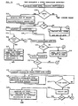
- Figure 9 indicates the process performed by a user processor for transferring an information frame to the bus adapter.
- the processor begins to retrieve a first header byte from its store (destination address) and transfers it to the bus via the adapter (actions 81-83). It also calculates and saves a CRC (cyclic redundancy check) residue correlated to the transferred byte (action 84) and updated the storage address function last used for (header) frame byte retrieval (as part of action 82).
- the bus adapter is enabled for transmission (control function E/T active in Figure 5), and passes the byte bit-serially out over the bus (preceded by a start bit and followed by a stop bit).
- the processor operates through the "yes" path of decision function 85 to monitor the bus receptively for collision (actions 86-89).
- the user processor .compares the received byte to a copy of the DA byte which it has saved. If they are not the same, collision is recognized, causing the processor to abort (deactivate the transmitter and receiver) and reschedule the transfer as explained previously (action 90). If the transfer is aborted, the processor terminates its transfer process and becomes available for other tasks (action 91).
- the processor sequences through the "no" path at decision stage 92 (since it is then handling the first byte of the frame) to retrieve and transfer the second header byte (OA) via action sequence 82-84. Taking the "no" path at decision 85 and the “yes” path at decision 93 (since the second header byte is then being handled), the processor repeats the collision sensing functions 86-89 and either defers the transfer (actions 90, 91) or continues it.
- the processor takes the action 82-84, the "no" path at decisions 85 and 93; and decision 95 -no transfer the remaining frame bytes without further collision monitoring-. It should be noted here that the combined time lengths of the DA and OA transfers exceed the maximal propagation delays between access nodes to the bus by a time sufficient to ensure that effects of any potential interference will have affected all nodes, and that the codes assigned to these bytes are sufficiently unique to ensure recognition of collision whenever it occurs.
- the processor After transferring the last informational byte of either the header or data portion of the frame, the processor takes the "yes" path at decision 95 and transfers the accumulated CRC residue for that portion (action 96). If the header transfer is then complete, the processor takes the "H" path at decision 97, determines if the frame contains a data portion (decision 98) and, if it does, proceeds to retrieve and transfer the bytes of that portion via action 99. If the frame does not contain data, the processor terminates via action 91. If data is sent, the sequence concludes with the data CRC transfer (action 96 and "D" exit at decision 97).
- Figure 10 illustrates the operations performed by the user processor for receiving a bus frame. Recall that when the Bus Available indication is active and a bus level transition is detected, the adapter presents an interruption to the user processor engaging the latter's attention. The receiving circuits of the adapter remain enabled and the first byte is received (using the stop-start transition as a time reference for sampling the bits of that byte). The first byte is passed from the adapter to the user processor, and evaluated by the latter as the destination address for the incoming frame (action 110).
- the "no" path is taken a decision stage 111 and the remainder of the frame is ignored. If the frame is directed to the local user (either specifically, or as a "broadcast” frame), the adapter/receiver remains enabled and the rest of the frame is handled via the action sequence starting at 112. The adapter/receiver receives each subsequent byte of the header, and passes it to the user processor. The latter develops the cumulative CRC residue for the entire header (including the first DA byte) and compares its final value to the received header CRC.
- the user processor verifies that the frame byte count value is 0 via decision action 115. If the byte count value is not 0, the processor terminates reception processing via action sequence 116; in which it first prepares a "reject" (RJCT) control frame directed to the source of the just received frame, and sets a "ready to send” indication. As noted previously, the "ready to send” prepares the local system to transmit the prepared frame when the bus available indication next activates.
- RJCT reject
- the user processor proceeds via the terminating action sequence 117 to: store the relevant information in the received frame for further processing, prepare an acknowledge frame directed to the source of the received frame, set a ready to send internal indication, and set an internal interruption request directed to the program task for processing the received information.
- the ready to send conditions the system to transmit the ACK frame and the interruption request conditions the system to process the received information when it can.
- the user processor would have taken the "information" path 118 at decision stage 114. In that path, the processor would first have determined at 119 that a "virtual" connection had been established between the local system and the frame source (e.g. by referring to information exchanged through earlier control and acknowledge frame communications). This determination would be made before the arrival of any data bytes. If the processor should find that the required connection did not exist, it would terminate the reception process via the "no" path through decision 120 and action sequence 116 mentioned previously, and thereby return a reject frame to the source of the received frame.
- the processor would first have determined at 119 that a "virtual" connection had been established between the local system and the frame source (e.g. by referring to information exchanged through earlier control and acknowledge frame communications). This determination would be made before the arrival of any data bytes. If the processor should find that the required connection did not exist, it would terminate the reception process via the "no" path through decision 120 and action sequence 116 mentioned previously, and thereby return a reject frame to the source of the
- the user processor would next verify through action 121 and decision 122 that the incoming frame has arrived (been received) in the proper sequence (by examining the S byte in the just received header and comparing it to a sequence count function locally developed). If the reception sequence is incorrect, the processor exits through the "no" path of decision 122 and returns a reject frame to the source of the received frame. If the frame is being received in its proper sequence, the processor prepares for reception of the data portion of the frame via action 123 and action sequence 124.
- the processor prepares the address of a storage space in which to store the next received data byte (action 123), receives the next byte when it is available at the adapter interface, stores that byte at the prepared address location, calculates and saves a cumulative CRC residue function and updates the address in preparation for reception and storage of the next byte.
- the processor acts through decision 125 to either repeat action sequence 124 for a next received byte or conclude the reception sequence if the last byte has been received.
- the processor compares the received CRC function to the cumulatively calculated/saved function at 126, 127 and returns either a retransmission request control frame (RET) or an ACK frame acknowledging correct reception to the source of the received frame.
- RET retransmission request control frame
- the processor sets an interruption request for evoking the internal programs responsible for processing the received data.
- the system just described permits users at different access nodes to the shared bus 1 ( Figures 1 and 2) to attempt to access the bus simultaneously (when it appears to be accessible), monitor for collision during transmittal of the first two frame bytes, and defer access when they detect collision.
- the access timers 18 ( Figure 5) at all user nodes would be programmed for identical timeout operations.
- the user systems at different access nodes have differently programmed access timers which effectively provide exclusive access "windows" to respective user systems at staggered times, and thereby permit only one user at a time to attempt to transmit on the bus. This embodiment is illustrated in Figures 11 and 12.
- bus adapters in these user systems have access counters 30a, 30b, etc., similar to the counter 30 in Figure 6, which are initially set with different delay constants K/A, K/B, etc., through respective loading gates 31a, 31b, etc. Consequently, the overflow outputs 164, 165, etc., of these counters become active at different times (assuming the bus remains at the stop level throughout their counting periods). These outputs in turn trigger respective single shot circuits "1S" to generate the respective availability pulse indications BA/A, BA/B, etc.
- the operations performed by the user processor during each byte transfer are related in real time to the respective transfer, and the byte length on the bus is tailored to allow for these operations to be completed. It should be understood that with sufficient stop time, the user processor could also perform operations unrelated to byte transfer but nevertheless useful to support reliable transfer; e.g. operations to test for faults in the adapter/transceiver and to isolate the latter from the bus when faulty.
Landscapes
- Engineering & Computer Science (AREA)
- Computer Networks & Wireless Communication (AREA)
- Signal Processing (AREA)
- Small-Scale Networks (AREA)
Applications Claiming Priority (2)
| Application Number | Priority Date | Filing Date | Title |
|---|---|---|---|
| US518176 | 1983-07-28 | ||
| US06/518,176 US4539677A (en) | 1983-07-28 | 1983-07-28 | Multiple access data communication system |
Publications (2)
| Publication Number | Publication Date |
|---|---|
| EP0132644A2 true EP0132644A2 (de) | 1985-02-13 |
| EP0132644A3 EP0132644A3 (de) | 1987-10-21 |
Family
ID=24062887
Family Applications (1)
| Application Number | Title | Priority Date | Filing Date |
|---|---|---|---|
| EP84107796A Withdrawn EP0132644A3 (de) | 1983-07-28 | 1984-07-05 | Verfahren und Vorrichtung zur Schnittstellenbildung zwischen einem Vielfachzugriffsbus und Benutzergeräten |
Country Status (3)
| Country | Link |
|---|---|
| US (1) | US4539677A (de) |
| EP (1) | EP0132644A3 (de) |
| JP (1) | JPS6043941A (de) |
Cited By (2)
| Publication number | Priority date | Publication date | Assignee | Title |
|---|---|---|---|---|
| EP0615366A1 (de) * | 1993-03-11 | 1994-09-14 | Ericsson Radio Systems B.V. | Verfahren und System zum Zugriff auf ein Übertragungsmedium bei asynchroner Übertragung |
| US7920596B2 (en) | 2006-01-04 | 2011-04-05 | Freescale Semiconductor, Inc. | Method for high speed framing and a device having framing capabilities |
Families Citing this family (28)
| Publication number | Priority date | Publication date | Assignee | Title |
|---|---|---|---|---|
| JPH0638600B2 (ja) * | 1983-12-28 | 1994-05-18 | 株式会社東芝 | ローカルエリアネットワークシステム |
| AU591057B2 (en) * | 1984-06-01 | 1989-11-30 | Digital Equipment Corporation | Local area network for digital data processing system |
| JPS6162263A (ja) * | 1984-09-04 | 1986-03-31 | Toshiba Corp | 情報伝送方式 |
| US4630259A (en) * | 1984-11-14 | 1986-12-16 | At&T Bell Laboratories | Lockup detection and recovery in a packet switching network |
| US4667191A (en) * | 1984-12-21 | 1987-05-19 | Motorola, Inc. | Serial link communications protocol |
| JPS61161842A (ja) * | 1985-01-11 | 1986-07-22 | Sharp Corp | 信号送出方式 |
| US4701756A (en) * | 1985-09-10 | 1987-10-20 | Burr William E | Fault-tolerant hierarchical network |
| JPS6276341A (ja) * | 1985-09-27 | 1987-04-08 | Toshiba Corp | 通信方法および装置 |
| US4896261A (en) * | 1986-11-24 | 1990-01-23 | Motorola Inc. | System for scheduling serial message transmission on a bus which is adoptable for rescheduling prioritized messages using a doubly-linked list |
| US4809362A (en) * | 1987-03-13 | 1989-02-28 | Center For Innovative Technology | Fiber-optic star tree network |
| US5487066A (en) * | 1988-03-21 | 1996-01-23 | First Pacific Networks, Inc. | Distributed intelligence network using time and frequency multiplexing |
| JPH01265869A (ja) * | 1988-04-19 | 1989-10-23 | Toshiro Mogi | 器形食品及びその製造方法 |
| US4972313A (en) * | 1989-08-07 | 1990-11-20 | Bull Hn Information Systems Inc. | Bus access control for a multi-host system using successively decremented arbitration delay periods to allocate bus access among the hosts |
| US5237570A (en) * | 1991-07-18 | 1993-08-17 | Motorola, Inc. | Prioritized data transfer method and apparatus for a radiotelephone peripheral |
| US5297142A (en) * | 1991-07-18 | 1994-03-22 | Motorola, Inc. | Data transfer method and apparatus for communication between a peripheral and a master |
| IE922611A1 (en) * | 1991-10-30 | 1993-05-05 | Motorola Inc | Method for data collision detection in a multi processor¹communication system |
| US5715407A (en) * | 1992-03-06 | 1998-02-03 | Rambus, Inc. | Process and apparatus for collision detection on a parallel bus by monitoring a first line of the bus during even bus cycles for indications of overlapping packets |
| USRE39879E1 (en) * | 1992-03-06 | 2007-10-09 | Rambus, Inc. | Method of transferring data by transmitting lower order and upper order memory address bits in separate words with respective op codes and start information |
| US5553265A (en) * | 1994-10-21 | 1996-09-03 | International Business Machines Corporation | Methods and system for merging data during cache checking and write-back cycles for memory reads and writes |
| US5602859A (en) * | 1994-12-19 | 1997-02-11 | Nec Corporation | Start-stop synchronous communicating method capable of correcting improper synchronization and system using the same |
| JP3607466B2 (ja) * | 1997-09-05 | 2005-01-05 | 株式会社東芝 | ルータ装置及び制御フレーム処理方法 |
| US6076160A (en) * | 1997-11-20 | 2000-06-13 | Advanced Micro Devices, Inc. | Hardware-based system for enabling data transfers between a CPU and chip set logic of a computer system on both edges of bus clock signal |
| DE10103092A1 (de) * | 2001-01-24 | 2002-07-25 | Philips Corp Intellectual Pty | Transceiver mit Mitteln zum Fehlermanagement |
| US8688780B2 (en) | 2005-09-30 | 2014-04-01 | Rockwell Automation Technologies, Inc. | Peer-to-peer exchange of data resources in a control system |
| JP4420009B2 (ja) * | 2006-11-02 | 2010-02-24 | セイコーエプソン株式会社 | 非同期シリアル通信方法及び非同期シリアル通信装置 |
| US7787375B2 (en) * | 2007-08-06 | 2010-08-31 | International Business Machines Corporation | Performing a recovery action in response to a credit depletion notification |
| US7975027B2 (en) * | 2007-08-06 | 2011-07-05 | International Business Machines Corporation | Credit depletion notification for transmitting frames between a port pair |
| CN110299941B (zh) * | 2019-05-23 | 2022-04-12 | 广东瑞谷光网通信股份有限公司 | 光模块IICReady Time精准测试方法、电子设备及计算机可读存储介质 |
Family Cites Families (11)
| Publication number | Priority date | Publication date | Assignee | Title |
|---|---|---|---|---|
| US3752932A (en) * | 1971-12-14 | 1973-08-14 | Ibm | Loop communications system |
| JPS5619144B2 (de) * | 1973-12-04 | 1981-05-06 | ||
| US3919461A (en) * | 1974-01-07 | 1975-11-11 | Engineered Syst Inc | Data transmission system |
| FR2269757A1 (en) * | 1974-05-03 | 1975-11-28 | Trindel | Bidirectional data transmission system - has interface module between line and each emitter-transmitter |
| US4210777A (en) * | 1978-06-15 | 1980-07-01 | Frederick Electronics Corp. | Pseudo-transparent stop bit generator |
| JPS5648743A (en) * | 1979-09-28 | 1981-05-02 | Canon Inc | Transmission system |
| US4395710A (en) * | 1980-11-26 | 1983-07-26 | Westinghouse Electric Corp. | Bus access circuit for high speed digital data communication |
| FR2507415A1 (fr) * | 1981-06-05 | 1982-12-10 | Ryckeboer Christian | Procede et dispositif pour la communication serie asynchrone de type multipoints de plusieurs emetteurs-recepteurs logiques |
| US4445193A (en) * | 1981-06-16 | 1984-04-24 | International Business Machines Corporation | Bisynchronous host/terminal communication system with non-clock-generating modem & PLL generated clock signal |
| JPS5859646A (ja) * | 1981-10-03 | 1983-04-08 | Sharp Corp | デ−タ通信方式 |
| US4412326A (en) * | 1981-10-23 | 1983-10-25 | Bell Telephone Laboratories, Inc. | Collision avoiding system, apparatus and protocol for a multiple access digital communications system including variable length packets |
-
1983
- 1983-07-28 US US06/518,176 patent/US4539677A/en not_active Expired - Fee Related
-
1984
- 1984-04-20 JP JP59078791A patent/JPS6043941A/ja active Pending
- 1984-07-05 EP EP84107796A patent/EP0132644A3/de not_active Withdrawn
Cited By (3)
| Publication number | Priority date | Publication date | Assignee | Title |
|---|---|---|---|---|
| EP0615366A1 (de) * | 1993-03-11 | 1994-09-14 | Ericsson Radio Systems B.V. | Verfahren und System zum Zugriff auf ein Übertragungsmedium bei asynchroner Übertragung |
| NL9300441A (nl) * | 1993-03-11 | 1994-10-03 | Ericsson Radio Systems Bv | Werkwijze voor het beveiligen van de integriteit van gegevens bij asynchrone transmissie over een gemeenschappelijke verbinding, en een communicatiestelsel voor toepassing van de werkwijze. |
| US7920596B2 (en) | 2006-01-04 | 2011-04-05 | Freescale Semiconductor, Inc. | Method for high speed framing and a device having framing capabilities |
Also Published As
| Publication number | Publication date |
|---|---|
| EP0132644A3 (de) | 1987-10-21 |
| US4539677A (en) | 1985-09-03 |
| JPS6043941A (ja) | 1985-03-08 |
Similar Documents
| Publication | Publication Date | Title |
|---|---|---|
| US4539677A (en) | Multiple access data communication system | |
| EP0076880B1 (de) | Lokales Netz mit Konkurrenzbetrieb für Datenkommunikationssysteme | |
| US4959833A (en) | Data transmission method and bus extender | |
| US5245616A (en) | Technique for acknowledging packets | |
| US6690719B1 (en) | Host to modem interface | |
| US5309562A (en) | Method and apparatus for establishing protocol spoofing from a modem | |
| EP0422914B1 (de) | Station zu Station Vollduplexkommunikation bei Kommunikationsnetzwerken | |
| EP0140077B1 (de) | Verfahren zur Zugriffssteuerung zum Übertragungsmedium in einem CSMA-System mit Kollisionsvermeidung | |
| US4988990A (en) | Dual master implied token communication system | |
| EP0146566B1 (de) | Schema zur verringerung der übertragungsverzögerung nach kollisionen in nachrichtennetzen | |
| US5166678A (en) | Dual master implied token communication system | |
| JPS639261B2 (de) | ||
| EP0004376A2 (de) | Bus-Kommunikationssystem mit Vielfachzugriff | |
| US5572546A (en) | Data communications system with multilink protocol | |
| US5933435A (en) | Optimized method of data communication and system employing same | |
| US4827477A (en) | Bus interface unit | |
| EP0439646B1 (de) | System und Protokoll für ein optisches Sternnetz mit minimaler Verzögerung zwischen aufeinanderfolgenden Datenpaketen | |
| US5378067A (en) | Network interface apparatus and method for reducing conflicts through the use of times | |
| EP0371593B1 (de) | Verfahren zur Initialisierung oder Synchronisierung einer Übertragungsleitung | |
| JP2986798B2 (ja) | データ伝送制御方法およびデータ通信装置 | |
| US4975907A (en) | Method and device for the asynchronous transmission of data by packets | |
| EP1051821B1 (de) | Arbitrierungsschema für ein serielles Interface | |
| JP4271787B2 (ja) | 通信システム | |
| JPH05103017A (ja) | 再送データ伝送方式 | |
| EP0132645A2 (de) | Verfahren und Vorrichtung zur Erleichterung der Kollisionserkennung |
Legal Events
| Date | Code | Title | Description |
|---|---|---|---|
| PUAI | Public reference made under article 153(3) epc to a published international application that has entered the european phase |
Free format text: ORIGINAL CODE: 0009012 |
|
| 17P | Request for examination filed |
Effective date: 19841123 |
|
| AK | Designated contracting states |
Designated state(s): DE FR GB |
|
| PUAL | Search report despatched |
Free format text: ORIGINAL CODE: 0009013 |
|
| AK | Designated contracting states |
Kind code of ref document: A3 Designated state(s): DE FR GB |
|
| 17Q | First examination report despatched |
Effective date: 19890712 |
|
| STAA | Information on the status of an ep patent application or granted ep patent |
Free format text: STATUS: THE APPLICATION IS DEEMED TO BE WITHDRAWN |
|
| 18D | Application deemed to be withdrawn |
Effective date: 19900123 |
|
| RIN1 | Information on inventor provided before grant (corrected) |
Inventor name: CHANG, YUAN |