EP0133558B1 - Dispositif pour appliquer une bande adhésive sur la couture d'un récipient en papier et procédé pour la mise en oeuvre du dispositif - Google Patents
Dispositif pour appliquer une bande adhésive sur la couture d'un récipient en papier et procédé pour la mise en oeuvre du dispositif Download PDFInfo
- Publication number
- EP0133558B1 EP0133558B1 EP84109238A EP84109238A EP0133558B1 EP 0133558 B1 EP0133558 B1 EP 0133558B1 EP 84109238 A EP84109238 A EP 84109238A EP 84109238 A EP84109238 A EP 84109238A EP 0133558 B1 EP0133558 B1 EP 0133558B1
- Authority
- EP
- European Patent Office
- Prior art keywords
- revolver
- tub
- adhesive strip
- circular path
- rail
- Prior art date
- Legal status (The legal status is an assumption and is not a legal conclusion. Google has not performed a legal analysis and makes no representation as to the accuracy of the status listed.)
- Expired
Links
- 238000000034 method Methods 0.000 title claims description 14
- 239000002390 adhesive tape Substances 0.000 title description 11
- 239000000853 adhesive Substances 0.000 claims abstract description 33
- 230000001070 adhesive effect Effects 0.000 claims abstract description 33
- 238000005520 cutting process Methods 0.000 claims abstract description 12
- 238000003825 pressing Methods 0.000 claims abstract description 3
- 238000004026 adhesive bonding Methods 0.000 description 10
- 238000004519 manufacturing process Methods 0.000 description 1
- 238000004806 packaging method and process Methods 0.000 description 1
Images
Classifications
-
- B—PERFORMING OPERATIONS; TRANSPORTING
- B65—CONVEYING; PACKING; STORING; HANDLING THIN OR FILAMENTARY MATERIAL
- B65B—MACHINES, APPARATUS OR DEVICES FOR, OR METHODS OF, PACKAGING ARTICLES OR MATERIALS; UNPACKING
- B65B7/00—Closing containers or receptacles after filling
- B65B7/16—Closing semi-rigid or rigid containers or receptacles not deformed by, or not taking-up shape of, contents, e.g. boxes or cartons
- B65B7/28—Closing semi-rigid or rigid containers or receptacles not deformed by, or not taking-up shape of, contents, e.g. boxes or cartons by applying separate preformed closures, e.g. lids, covers
- B65B7/2842—Securing closures on containers
- B65B7/2864—Securing closures on containers by adhesive tape
Definitions
- the invention relates to a device for applying an adhesive strip to the seam encircling between the fuselage and the lid of a cardboard barrel with a lower rotary plate forming the base of the vertical barrel and an upper rotary plate for pressing the lid onto the fuselage, at least one of the corresponding rotary plates being coaxial and can be moved axially downwards and the turntables on a rotary machine are both rotatable about their own axis and movably mounted on a circular path with the help of the rotary machine, and arranged on the circumference of the rotary machine at the level of the interface between the upper and lower rotary table , fixed adhesive cutting machines.
- the invention further relates to a method for operating the device in which a single drum with a loosely placed lid is fed to a rotary machine, on which it is acted upon by an adhesive strip which closes the seam between the body and lid of the drum and rotates on its own axis on a circular path on a circular path the automatic adhesive cutting machine that feeds the adhesive tape and is removed from the rotary machine after the seam has been closed with the adhesive tape.
- Such a device and a method for operating this device are known from FR-A-22 73 447, in which, however, the seam between the fuselage and the loosely placed lid of a container using a stationary, rotating adhesive-cutting machine Closure strip is applied.
- the adhesive strip is held on the circumference of the machine until the adhesive strip is applied to the rotating container.
- This device and the method for its operation only permit discontinuous work, that is to say that the adhesive strip can only be applied discontinuously and the work steps for gluing one barrel each have to be carried out completely before the gluing of the next barrel can begin. In practice, therefore, a performance limit of 40 to 45 barrels per minute cannot be exceeded. Since the continuous flow principle is preferred for the packaging lines by the machine manufacturers for reasons of higher performance, the strip adhesives of this type represent a bottleneck in production.
- the invention has for its object to provide a solution for a continuous working method for quickly applying the adhesive strips to the seam between the body and lid of cardboard barrels.
- the automatic adhesive-cutting machine has a carriage with rollers for gluing the beginning of the strip in the radial direction with respect to the circular path, and that the rotary machine for guiding leads to the barrel that is moved past the circular path of the adhesive tape, which has not yet been fully bonded, is equipped with a spatially fixed, in particular U-shaped rail on the circumference of the rotary device and with the rotary device which is moved and engages in the rail, in particular with spring-mounted rollers.
- cardboard drums can be quickly and safely provided with adhesive strips in a continuous working process which enables a high throughput of cardboard drums per unit of time.
- the invention provides that the rotary machine receives two pairs of turntables arranged diametrically with respect to its axis.
- the rotary machine thus preferably has two upper and lower turntables, so that "during the gluing of the beginning of the adhesive strip on a barrel, the gluing process begun can be carried out to the end at the previous barrel.
- the above object is achieved in that the beginning of the adhesive strip on the circumference of the drum is fixed with the aid of a carriage which is movable in the radial direction with respect to the circular path and is provided with rollers, and the adhesive strip when the drum is moved after a
- the circumference of the barrel is separated and the adhesive strip pulled by the barrel until it is completely glued to the barrel circumference is guided in a fixed, in particular U-shaped, rail on the circumference of the rotary machine and by rollers which move with the rotary machine and engage in the rail, in particular spring-mounted rollers in the rail is held.
- the drums with the lid lying loosely on top are stowed vertically by a conveyor belt in front of an allotment star and pushed synchronously by an infeed star onto the respective lower turntable of the rotary machine.
- the rotating upper rotary plate is then pressed axially against the barrel, preferably up to a fixed stop, the lower plate depending on the height or the height tolerances of the barrel against an elastic counter pressure can be stored alternately downwards.
- the barrel that moves on a circular path after being placed on the turntable and at the same time rotated about its own axis passes the automatic glue-cutting machine on the circular path.
- the movement there for the gluing process e.g. B. interrupted by a brake and an intermediate gear for a fraction of a second.
- the barrel which moves on the circular path and rotates about its own axis pulls the adhesive strip behind it, the tape end which has not yet been glued held in a guide, preferably between a U-shaped rail and spring-mounted rollers.
- the adhesive cutting machine is also equipped with a knife or the like, which cuts off the adhesive tape after unwinding a barrel circumference, so that the rest of the adhesive tape can be held by the guide until it is completely glued by the barrel's own rotation.
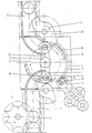
- an arrangement according to the invention is shown in plan view or in horizontal section.
- the drums 2 arriving on the driven belt 1 are jammed with the aid of an allotment star 3 and are fed synchronously to the inlet star 4 of the gluing system, which is denoted overall by 5.
- the inlet star 4 passes the respective barrel 2 to the pair of rotating plates 6 and 6 just moved past.
- the rotating plates rotate the barrel 2 about the barrel or turntable axis 7 and at the same time on a circular path 8 around the vertical and parallel to Turntable axis 7 extending pivot axis 9 of a rotary rotor 10 carrying the turntable 6 moves.
- the rotary machine 10 carries in the embodiment shown in the drawing a pair of upper and lower rotary plates 6.
- the feed on the circular path 8 is preferably briefly braked, so that the rollers mounted on the slide 12 13 can press the adhesive tape 14 for example by a back and forth movement on the barrel 2 for the first gluing process.
- the barrel 2 is transported further in the turntables 6 in the direction of arrow 15 with its own rotation. If the direction of rotation of the circular movements 8 and 15 carried out simultaneously by the barrel coincides, the barrel 2 transported further pulls the adhesive tape 14 behind it.
- the adhesive strip 14 is advantageously held and guided between a U-shaped rail 17 and rollers 18 until it is completely glued to the barrel.
- the U-shaped rail 17 is stationary, for. B. connected to the gluing machine 11, while the rollers 18 are held in a bearing arm 19 carried with the rotary machine 10.
Landscapes
- Engineering & Computer Science (AREA)
- Mechanical Engineering (AREA)
- Package Closures (AREA)
- Making Paper Articles (AREA)
- Auxiliary Devices For And Details Of Packaging Control (AREA)
- Closing Of Containers (AREA)
- Rigid Containers With Two Or More Constituent Elements (AREA)
- Closures For Containers (AREA)
Claims (5)
Priority Applications (1)
| Application Number | Priority Date | Filing Date | Title |
|---|---|---|---|
| AT84109238T ATE32051T1 (de) | 1983-08-11 | 1984-08-03 | Vorrichtung zum aufbringen eines klebestreifens auf die naht eines pappfasses und verfahren zum betrieb der vorrichtung. |
Applications Claiming Priority (2)
| Application Number | Priority Date | Filing Date | Title |
|---|---|---|---|
| DE19833329007 DE3329007A1 (de) | 1983-08-11 | 1983-08-11 | Vorrichtung zum aufbringen eines klebestreifens auf die naht eines pappfasses und verfahren zum betrieb der vorrichtung |
| DE3329007 | 1983-08-11 |
Publications (3)
| Publication Number | Publication Date |
|---|---|
| EP0133558A2 EP0133558A2 (fr) | 1985-02-27 |
| EP0133558A3 EP0133558A3 (en) | 1986-03-12 |
| EP0133558B1 true EP0133558B1 (fr) | 1988-01-20 |
Family
ID=6206312
Family Applications (1)
| Application Number | Title | Priority Date | Filing Date |
|---|---|---|---|
| EP84109238A Expired EP0133558B1 (fr) | 1983-08-11 | 1984-08-03 | Dispositif pour appliquer une bande adhésive sur la couture d'un récipient en papier et procédé pour la mise en oeuvre du dispositif |
Country Status (4)
| Country | Link |
|---|---|
| EP (1) | EP0133558B1 (fr) |
| AT (1) | ATE32051T1 (fr) |
| DE (2) | DE3329007A1 (fr) |
| ES (2) | ES8504597A1 (fr) |
Families Citing this family (6)
| Publication number | Priority date | Publication date | Assignee | Title |
|---|---|---|---|---|
| IT1280811B1 (it) * | 1995-03-21 | 1998-02-11 | Hitech Systems Srl | Dispositivo per la termosigillatura in continuo di involucri di confezionamento di materiale polimerico termosaldabile e macchine |
| EP1648774B1 (fr) * | 2003-07-17 | 2015-07-01 | Induflex Robert Morgan | Dispositif tournant |
| US7886800B2 (en) | 2004-09-24 | 2011-02-15 | The Trustees Of The University Of Pennsylvania | Apparatus and method for applying tape |
| CN101367444B (zh) * | 2008-09-07 | 2011-05-04 | 浙江圣雷机械有限公司 | 自动对封贴标包装机 |
| CN107472595B (zh) * | 2016-06-08 | 2024-03-22 | 浙江机电职业技术学院 | 粘胶带装置及纸箱包装机 |
| CN109956102B (zh) * | 2019-03-13 | 2019-11-12 | 浙江大洪包装科技有限公司 | 一种纸箱包装机 |
Family Cites Families (2)
| Publication number | Priority date | Publication date | Assignee | Title |
|---|---|---|---|---|
| US3555764A (en) * | 1967-02-01 | 1971-01-19 | Continental Can Co | Apparatus and method for securing closures to container bodies |
| IT1013633B (it) * | 1974-05-31 | 1977-03-30 | Grandi R | Sigillatrice continua per scatola di formato rotondo |
-
1983
- 1983-08-11 DE DE19833329007 patent/DE3329007A1/de not_active Withdrawn
-
1984
- 1984-08-03 EP EP84109238A patent/EP0133558B1/fr not_active Expired
- 1984-08-03 DE DE8484109238T patent/DE3468853D1/de not_active Expired
- 1984-08-03 AT AT84109238T patent/ATE32051T1/de not_active IP Right Cessation
- 1984-08-10 ES ES535087A patent/ES8504597A1/es not_active Expired
- 1984-08-10 ES ES1984281055U patent/ES281055Y/es not_active Expired
Also Published As
| Publication number | Publication date |
|---|---|
| EP0133558A2 (fr) | 1985-02-27 |
| ES535087A0 (es) | 1985-05-01 |
| ES281055U (es) | 1985-01-16 |
| ES281055Y (es) | 1985-07-16 |
| EP0133558A3 (en) | 1986-03-12 |
| ES8504597A1 (es) | 1985-05-01 |
| ATE32051T1 (de) | 1988-02-15 |
| DE3329007A1 (de) | 1985-02-28 |
| DE3468853D1 (en) | 1988-02-25 |
Similar Documents
| Publication | Publication Date | Title |
|---|---|---|
| DE3142202C2 (fr) | ||
| DE3109529A1 (de) | Vorrichtung zum verbinden des hinteren endes einer von einer auslaufenden rolle abgezogenen bahn mit dem vorderen ende einer von einer ersatzrolle abgezogenen bahn | |
| EP0462157B1 (fr) | Dispositif pour relier des bandes de materiau | |
| DE2930474B1 (de) | Doppeltragwalzenwickelmaschine | |
| EP0133558B1 (fr) | Dispositif pour appliquer une bande adhésive sur la couture d'un récipient en papier et procédé pour la mise en oeuvre du dispositif | |
| DE19540689A1 (de) | Schneideeinrichtung | |
| EP0305956A2 (fr) | Dispositif pour emballer des barres cylindriques composées d'une pluralité de pièces discoides | |
| EP3507224B1 (fr) | Dispositif pour enrouler un fil | |
| DE3308059C2 (fr) | ||
| EP0562304A1 (fr) | Procédé et dispositif pour attacher des étiquettes à ficelle aux récipients | |
| DE2647556C3 (de) | Vorrichtung zum mehrbahnigen Aufbringen von Haftetiketten | |
| DE2755625A1 (de) | Schneidvorrichtung | |
| DE3834334C2 (de) | Bearbeitungseinrichtung zur Vorbereitung des Bahnendes einer Rolle einer Warenbahn | |
| DE19604563A1 (de) | Vorrichtung und Verfahren zur Herstellung einer Mehrfachverpackung sowie eine durch das Verfahren hergestellte Mehrfachverpackung | |
| EP0385082B1 (fr) | Dispositif pour enrouler une feuille continue sur des mandrins avec application de colle | |
| EP1318092A2 (fr) | Méthode et dispositif pour le raccordement de bandes de matériau | |
| DE10202462B4 (de) | Vorrichtung zum kontinuierlichen Aufwickeln von Bahnen | |
| DE4318579C2 (de) | Vorrichtung zum Ablängen und Lochen von streifenförmigem Band | |
| DE2248569C3 (de) | Vorrichtung zum Verbinden einer von einer Wickelrolle ablaufenden Bahn mit einer neuen Bahn | |
| DE2654707A1 (de) | Vorrichtung zum entfernen von auf einem wickelkern gebildeten wickeln von einer welle und gleichzeitigem anordnen leerer wickelkerne auf dieser welle | |
| DE2243504A1 (de) | Verfahren und vorrichtung zum automatischen aufwickeln von bandmaterial | |
| DE8323152U1 (de) | Vorrichtung zum Aufbringen eines Klebestreifens auf die Naht eines Pappfasses | |
| EP4532189A1 (fr) | Procédé et dispositif pour appliquer des bandes de déchirage sur une bande de matériau continue | |
| DE3515782A1 (de) | Vorrichtung zum aufbringen eines dichtungsbandes auf eine leiste | |
| WO2005110859A1 (fr) | Systeme pour changer un rouleau d'etiquettes |
Legal Events
| Date | Code | Title | Description |
|---|---|---|---|
| PUAI | Public reference made under article 153(3) epc to a published international application that has entered the european phase |
Free format text: ORIGINAL CODE: 0009012 |
|
| AK | Designated contracting states |
Designated state(s): AT BE CH DE FR GB IT LI LU NL SE |
|
| PUAL | Search report despatched |
Free format text: ORIGINAL CODE: 0009013 |
|
| AK | Designated contracting states |
Kind code of ref document: A3 Designated state(s): AT BE CH DE FR GB IT LI LU NL SE |
|
| 17P | Request for examination filed |
Effective date: 19860329 |
|
| 17Q | First examination report despatched |
Effective date: 19861121 |
|
| GRAA | (expected) grant |
Free format text: ORIGINAL CODE: 0009210 |
|
| AK | Designated contracting states |
Kind code of ref document: B1 Designated state(s): AT BE CH DE FR GB IT LI NL |
|
| REF | Corresponds to: |
Ref document number: 32051 Country of ref document: AT Date of ref document: 19880215 Kind code of ref document: T |
|
| GBT | Gb: translation of ep patent filed (gb section 77(6)(a)/1977) | ||
| REF | Corresponds to: |
Ref document number: 3468853 Country of ref document: DE Date of ref document: 19880225 |
|
| ITF | It: translation for a ep patent filed | ||
| ET | Fr: translation filed | ||
| PLBE | No opposition filed within time limit |
Free format text: ORIGINAL CODE: 0009261 |
|
| STAA | Information on the status of an ep patent application or granted ep patent |
Free format text: STATUS: NO OPPOSITION FILED WITHIN TIME LIMIT |
|
| 26N | No opposition filed | ||
| PGFP | Annual fee paid to national office [announced via postgrant information from national office to epo] |
Ref country code: GB Payment date: 19900720 Year of fee payment: 7 Ref country code: CH Payment date: 19900720 Year of fee payment: 7 |
|
| PGFP | Annual fee paid to national office [announced via postgrant information from national office to epo] |
Ref country code: DE Payment date: 19900727 Year of fee payment: 7 |
|
| PGFP | Annual fee paid to national office [announced via postgrant information from national office to epo] |
Ref country code: AT Payment date: 19900803 Year of fee payment: 7 |
|
| PGFP | Annual fee paid to national office [announced via postgrant information from national office to epo] |
Ref country code: FR Payment date: 19900807 Year of fee payment: 7 |
|
| ITTA | It: last paid annual fee | ||
| PGFP | Annual fee paid to national office [announced via postgrant information from national office to epo] |
Ref country code: NL Payment date: 19900831 Year of fee payment: 7 |
|
| PGFP | Annual fee paid to national office [announced via postgrant information from national office to epo] |
Ref country code: BE Payment date: 19900904 Year of fee payment: 7 |
|
| PG25 | Lapsed in a contracting state [announced via postgrant information from national office to epo] |
Ref country code: GB Effective date: 19910803 Ref country code: AT Effective date: 19910803 |
|
| PG25 | Lapsed in a contracting state [announced via postgrant information from national office to epo] |
Ref country code: LI Effective date: 19910831 Ref country code: CH Effective date: 19910831 Ref country code: BE Effective date: 19910831 |
|
| BERE | Be: lapsed |
Owner name: HENKEL K.G.A.A. Effective date: 19910831 |
|
| PG25 | Lapsed in a contracting state [announced via postgrant information from national office to epo] |
Ref country code: NL Effective date: 19920301 |
|
| GBPC | Gb: european patent ceased through non-payment of renewal fee | ||
| NLV4 | Nl: lapsed or anulled due to non-payment of the annual fee | ||
| PG25 | Lapsed in a contracting state [announced via postgrant information from national office to epo] |
Ref country code: FR Effective date: 19920430 |
|
| REG | Reference to a national code |
Ref country code: CH Ref legal event code: PL |
|
| PG25 | Lapsed in a contracting state [announced via postgrant information from national office to epo] |
Ref country code: DE Effective date: 19920501 |
|
| REG | Reference to a national code |
Ref country code: FR Ref legal event code: ST |