EP0134583A2 - Revêtement pour façades - Google Patents
Revêtement pour façades Download PDFInfo
- Publication number
- EP0134583A2 EP0134583A2 EP84110670A EP84110670A EP0134583A2 EP 0134583 A2 EP0134583 A2 EP 0134583A2 EP 84110670 A EP84110670 A EP 84110670A EP 84110670 A EP84110670 A EP 84110670A EP 0134583 A2 EP0134583 A2 EP 0134583A2
- Authority
- EP
- European Patent Office
- Prior art keywords
- cladding
- vertical
- panel
- plate
- facade
- Prior art date
- Legal status (The legal status is an assumption and is not a legal conclusion. Google has not performed a legal analysis and makes no representation as to the accuracy of the status listed.)
- Granted
Links
Images


Classifications
-
- E—FIXED CONSTRUCTIONS
- E04—BUILDING
- E04F—FINISHING WORK ON BUILDINGS, e.g. STAIRS, FLOORS
- E04F13/00—Coverings or linings, e.g. for walls or ceilings
- E04F13/07—Coverings or linings, e.g. for walls or ceilings composed of covering or lining elements; Sub-structures therefor; Fastening means therefor
- E04F13/08—Coverings or linings, e.g. for walls or ceilings composed of covering or lining elements; Sub-structures therefor; Fastening means therefor composed of a plurality of similar covering or lining elements
- E04F13/0864—Coverings or linings, e.g. for walls or ceilings composed of covering or lining elements; Sub-structures therefor; Fastening means therefor composed of a plurality of similar covering or lining elements composed of superposed elements which overlap each other and of which the flat outer surface includes an acute angle with the surface to cover
Definitions
- the invention relates to a facade cladding for house walls or the like.
- cladding panels are fastened in a mutually overlapping arrangement to a substructure on vertically arranged support conductors fastened to the wall.
- the object of the invention is therefore to provide a facade cladding of the type mentioned in which change of individual cladding panels is possible without the need to remove adjacent cladding panels or parts of the facade cladding.
- the assembly of the facade cladding is therefore easy.
- the location of the cladding panel to be assembled is determined by the receiving parts and supporting surfaces on the carrier conductors in cooperation with the hanging part and the correspondingly shaped rear side of the cladding panel, so that a remeasurement and alignment of the cladding panels is not necessary during assembly.
- the individual cladding panels can also be easily removed from the facade cladding, for which it is only necessary to lift the corresponding cladding panel upwards and lift it out of the hook-shaped receiving part, in which the hook-shaped hook-in part engages on the back of the cladding panel.
- the hook-shaped receiving part and the hook-shaped hanging part are released from each other, so that a Swiveling the lower plate part outwards is possible and the plate can also be removed from the facade cladding on its upper part between the supporting surface and the lower edge of the cladding plate above. Reinstalling a new cladding panel is done in reverse installation.
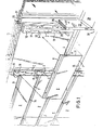
- strips 16, in particular made of wood, are attached to a house wall 15.
- Carrier strips 1 for receiving cladding panels 2 are fastened to these wooden strips 16.
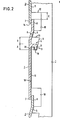
- the carrier strips 1 each have a hook-shaped receiving part 3 for each cladding panel 2, into which a hook-shaped hanging part 4 present on the rear of the cladding panel 2 is inserted during assembly.
- a support surface 5 which is inclined with respect to the vertical is provided above the hook-shaped receiving part 3 on the carrier conductor 1. against this inclined support surface 5 is in the installed state of the cladding panel 2, i.e. when it is in a vertical position; an opposite to the vertical support surface 6 on the back of the panel 2.
- an upper plate part 8 of the cladding plate lies behind a lower plate part 7 of the cladding plate 2 located above it.
- the lower plate part 7 of the cladding plate lies with its vertical rear surface 10 against a vertical contact surface 11, which can also be designed as a contact edge, on the carrier line - .ter 1 at.
- the hook-shaped receiving part 3 of the carrier conductor 1 also has an inclined guide surface 9, on which the hanging part 4 bears on its rear surface 17 to improve the press fit.
- the cladding panel 2 therefore has below the hook-shaped hanging part 4, when it occupies a vertical position, the vertical rear surface 10, which bears against the vertical contact surface 11 or contact edge of the carrier conductor 1, and the vertical front surface on the lower part 7.
- These vertical front surfaces on the lower plate parts 7 of the cladding panels 2 mounted in the facade cladding lie in a same vertical plane.
- the cladding plate 2 which occupies a vertical position, has on the back the support surface 6 which is inclined with respect to the vertical and which bears against the support conductor 1 against the likewise inclined support surface 5.
- the front surface of the cladding panel 2 also has an oblique course in this area, so that the vertical front surface of the upper panel part 8 comes to lie behind the rear surface of the lower panel part 7 of the overlying panel panel 2.
- the distance A of the upper edge of the hook-shaped hanging part 4 from its lower edge is dimensioned smaller than the distances B from the upper edge of the hook-shaped hanging part 4 to the lower edge 13 of the inclined support surface 5 and C from the upper edge of the upper plate part 8 to the lower edge 12 of the vertical contact surface 11.
- This enables the hook-shaped hanging part 4 to be released from the hook-shaped receiving part 3 by lifting the cladding plate 2 and tilting the lower plate part 7 outwards, as shown in FIG. 3. In this way, the cladding panel 2 can be easily removed from the facade cladding.
- a correspondingly large recess 18 is provided in the carrier conductor 1. 3e according to which of the two distances B and C is larger, when inserting or removing the cladding panel 2, this is with its hook-shaped hanging part 4 on the lower edge 13 of the support surface 5 or with the upper edge of the upper plate part 8 on the lower edge 12 of the vertical Contact surface 11.
- the upper plate part 8 is also pressed against the rear surface of the lower plate part 7 of the covering plate 2 located above it. Furthermore, the rear surface 10 of the lower plate part 7 is also firmly seated against the vertical contact surface 11 on the carrier ladder 1. This results in a vibration-proof fit of the cladding plate in the facade cladding, which, however, is; as has already been explained in the foregoing, can be released again simply by simply lifting the covering panel and tilting it outward.
- a tight connection to the side edges of the cladding panels 2 or to the lateral boundary of the substructure can be achieved at window and door openings with special elements 22, in particular in plate form, which are fastened to the wooden strips 16 .
- the side surfaces 23 and 24 of the wooden strip 16 or the corresponding substructure part and the support strip 1 fastened thereon, which form the lateral boundary of the substructure at the door or window opening, lie in one plane.
- curtain piece 36 of the reveal which is present between the door or window lining 31 and the substructure or the wooden strip 16, can be set back with respect to this plane of the side surfaces 23 and 24.
- a sealing compound can be filled.
- the grooves 27 and 28 present in the exemplary embodiment shown are particularly suitable for filling this sealing compound in the surface of the special element 22 which faces the side surfaces 23 and 24.
- the special element 22 lies in a form-fitting manner with its lower edge on the window ledge 29 if the special element forms the lateral boundary in a window opening.
- the vertical part 30 of the window ledge trim is aligned with its lower edge with the lower edge of the adjacent trim panel 2, which is at the same height.
- a continuous line remains in the area of the window opening on the lower edges of the corresponding cladding panels lying at the same height, so that the cladding panels lying under the window opening come to lie behind the vertical part 30 of the window ledge cladding with their corresponding upper panel parts 8. In this way, the continuity of the surface of the facade cladding is maintained even in the area of the window openings.
- the plate-shaped special element 22 in the area of the window or door reveal 31 achieves a completely tight seal on the lateral boundary of the substructure and the cladding panels.
- the cladding panels 2 can be extended accordingly and have a miter 25 for connection to one another, so that a positive connection is present at the corner connection.
- the two side surfaces abutting support conductors 1 form two in a corner with the back surfaces of the forming at the front corner of the form-fitting corner joint facing panels 2 is a cavity, which may optionally be filled with a non-illustrated sealing compound can.
- a cavity which may optionally be filled with a non-illustrated sealing compound can.
- an essentially rectangular cavity is formed.
- the two side surfaces of the carrier conductors 1 meet at right angles in the illustrated embodiment.
- the two carrier conductors 1 are fastened to wooden strips 16 which abut one another at right angles on the house corner.
- the carrier conductors 1 have an essentially U-shaped profile, the profile webs of which rest on the wooden strips 18 and are fastened there, for example, by means of screws or the like.
- the desired oblique support surfaces 5, the recess 18 and the hook parts 20 for the Einteineteii 4 are through corresponding punched holes on the side flanges of the U-shaped profile of the carrier ladders achieved.
- the support surfaces 5 are formed by the corresponding front edges of the profile flanges. This also applies to the vertical contact surfaces 1 and the guide surfaces 9 in the region of the hook-shaped receiving part 3.
- these areas can be widened by folding the corresponding areas so that they form a larger contact area. These folds can preferably be bent into the interior of the U-profile.
- a further embodiment of the carrier conductors can consist in that they consist of solid material and the recesses 18, the inclined support surfaces 5 and the hook-shaped receiving parts 3 are correspondingly formed by milling or otherwise.
Landscapes
- Engineering & Computer Science (AREA)
- Architecture (AREA)
- Civil Engineering (AREA)
- Structural Engineering (AREA)
- Finishing Walls (AREA)
- Ropes Or Cables (AREA)
- Extrusion Moulding Of Plastics Or The Like (AREA)
Priority Applications (1)
| Application Number | Priority Date | Filing Date | Title |
|---|---|---|---|
| AT84110670T ATE31770T1 (de) | 1983-09-09 | 1984-09-07 | Fassadenverkleidung. |
Applications Claiming Priority (2)
| Application Number | Priority Date | Filing Date | Title |
|---|---|---|---|
| DE3332623 | 1983-09-09 | ||
| DE19833332623 DE3332623A1 (de) | 1983-09-09 | 1983-09-09 | Fassadenverkleidung |
Publications (3)
| Publication Number | Publication Date |
|---|---|
| EP0134583A2 true EP0134583A2 (fr) | 1985-03-20 |
| EP0134583A3 EP0134583A3 (en) | 1986-04-09 |
| EP0134583B1 EP0134583B1 (fr) | 1988-01-07 |
Family
ID=6208676
Family Applications (1)
| Application Number | Title | Priority Date | Filing Date |
|---|---|---|---|
| EP84110670A Expired EP0134583B1 (fr) | 1983-09-09 | 1984-09-07 | Revêtement pour façades |
Country Status (3)
| Country | Link |
|---|---|
| EP (1) | EP0134583B1 (fr) |
| AT (1) | ATE31770T1 (fr) |
| DE (1) | DE3332623A1 (fr) |
Cited By (2)
| Publication number | Priority date | Publication date | Assignee | Title |
|---|---|---|---|---|
| GB2468161A (en) * | 2009-02-28 | 2010-09-01 | Aggregate Ind Uk Ltd | A cladding element with integral hook-shaped mounting member |
| WO2010099848A1 (fr) * | 2009-03-06 | 2010-09-10 | Creaton Ag | Dispositif pour la fixation d'éléments de façade et élément de façade |
Families Citing this family (3)
| Publication number | Priority date | Publication date | Assignee | Title |
|---|---|---|---|---|
| RU2121552C1 (ru) * | 1997-08-12 | 1998-11-10 | Всероссийский федеральный научно-исследовательский и проектно-конструкторский технологический институт строительной индустрии | Защитно-декоративная облицовка стен и потолков и способ ее крепления |
| AUPR772901A0 (en) * | 2001-09-18 | 2001-10-11 | Bisschops, Wayne Cornelis | A panel securing device |
| EP3583275A4 (fr) * | 2017-02-17 | 2021-01-06 | Nokelainen, Mika | Procédé et système de couverture d'une structure de paroi |
Family Cites Families (11)
| Publication number | Priority date | Publication date | Assignee | Title |
|---|---|---|---|---|
| GB679956A (en) * | 1949-05-09 | 1952-09-24 | William Cookson | Improvements in closures for weatherboarding and the like |
| US3261136A (en) * | 1963-10-10 | 1966-07-19 | Weyerhaeuser Co | Fastening means for supporting siding panels |
| GB1080827A (en) * | 1965-04-14 | 1967-08-23 | George Kendrick Findlay | Improvements in and relating to wall claddings for building structures |
| US3347009A (en) * | 1965-04-16 | 1967-10-17 | Olin Mathieson | Selectively removable panel assembly |
| LU51798A1 (fr) * | 1965-08-27 | 1966-10-24 | ||
| SE345242B (fr) * | 1968-12-09 | 1972-05-23 | Saab Scania Ab | |
| SE321068B (fr) * | 1968-12-09 | 1970-02-23 | Bostadsforskning Ab | |
| FR2077437A1 (fr) * | 1970-03-23 | 1971-10-29 | Skandinaviska Eternit | |
| CH637181A5 (de) * | 1977-04-21 | 1983-07-15 | Michael Christian Ludowici | Fassadenverkleidung. |
| DE2717798C2 (de) * | 1977-04-21 | 1986-08-28 | Michael Christian 8013 Haar Ludowici | Fassadenplatte |
| DE2804173A1 (de) * | 1978-02-01 | 1979-08-09 | Gul Chandiramani | Profilleiste und wandflaechenelement fuer in fertigbauweise zu erstellende gebaeude o.dgl. |
-
1983
- 1983-09-09 DE DE19833332623 patent/DE3332623A1/de active Granted
-
1984
- 1984-09-07 AT AT84110670T patent/ATE31770T1/de not_active IP Right Cessation
- 1984-09-07 EP EP84110670A patent/EP0134583B1/fr not_active Expired
Cited By (2)
| Publication number | Priority date | Publication date | Assignee | Title |
|---|---|---|---|---|
| GB2468161A (en) * | 2009-02-28 | 2010-09-01 | Aggregate Ind Uk Ltd | A cladding element with integral hook-shaped mounting member |
| WO2010099848A1 (fr) * | 2009-03-06 | 2010-09-10 | Creaton Ag | Dispositif pour la fixation d'éléments de façade et élément de façade |
Also Published As
| Publication number | Publication date |
|---|---|
| EP0134583A3 (en) | 1986-04-09 |
| DE3332623A1 (de) | 1985-04-04 |
| EP0134583B1 (fr) | 1988-01-07 |
| ATE31770T1 (de) | 1988-01-15 |
| DE3332623C2 (fr) | 1988-05-19 |
Similar Documents
| Publication | Publication Date | Title |
|---|---|---|
| DE69016091T2 (de) | Wandvertäfelungssystem. | |
| DE3688977T2 (de) | System von trennwandplatten. | |
| DE2621458A1 (de) | Aussenfenstereinheit mit einem grundbalkenvorsatzstueck | |
| DE3634128A1 (de) | Zusammenfassung eines mit aufgesetzten rolladenfuehrungen versehenen blendrahmens mit einem ihm zugeordneten rolladenkasten | |
| EP3563738B1 (fr) | Étagère de douche | |
| EP0114220B1 (fr) | Cale pour la fixation de vitres ou similaires dans des cadres de portes ou fenêtres | |
| DE4005953C2 (fr) | ||
| EP0520132B1 (fr) | Revêtement pour façades de bâtiments ou semblables | |
| EP0134583B1 (fr) | Revêtement pour façades | |
| EP0278364B1 (fr) | Dispositif pour le recouvrement d'ouvertures de portes et de fenêtres dans les bâtiments | |
| EP0037120A1 (fr) | Fenêtre ou porte | |
| DE29706302U1 (de) | Tragkonstruktion für Innenwände | |
| EP0180163A2 (fr) | Battant pour volets, portes de la maison, porte de la pièce et portes de l'armoire à partir de persienne | |
| EP0409029B1 (fr) | Profilé pour le support de panneaux de plafond | |
| DE3426653A1 (de) | Dachgaube | |
| EP0400374A2 (fr) | Dispositif pour la fixation de vitres dans des cadres de porte ou de fenêtre | |
| EP0130561A2 (fr) | Revêtement de paroi | |
| DE3733359A1 (de) | An einer gebaeudewand anbringbare fassade | |
| EP0013988B1 (fr) | Liaison démontable entre deux éléments de construction plats ou en forme de coquille, par exemple pour murs, planchers, plafonds ou analogues | |
| DE9200503U1 (de) | Faltstore mit Kederprofilbefestigung | |
| DE3702534A1 (de) | Befestigungsvorrichtung fuer fassadenplatten | |
| EP0835979B1 (fr) | Volet roulant et son cache intérieure | |
| DE3240605C2 (de) | Klammer zur Befestigung einer Mauerfugen-Blende an den Zargenholmen eines Tores od. dgl. | |
| DE8236198U1 (de) | Klotzbruecke oder gitterklotz zum festsetzen von glasscheiben od. dgl. in tuer- oder fensterrahmen | |
| DE1654034C3 (de) | Kopfschiene einer raffbaren Lamellenjalousie |
Legal Events
| Date | Code | Title | Description |
|---|---|---|---|
| PUAI | Public reference made under article 153(3) epc to a published international application that has entered the european phase |
Free format text: ORIGINAL CODE: 0009012 |
|
| AK | Designated contracting states |
Designated state(s): AT BE CH FR GB LI NL SE |
|
| PUAL | Search report despatched |
Free format text: ORIGINAL CODE: 0009013 |
|
| AK | Designated contracting states |
Kind code of ref document: A3 Designated state(s): AT BE CH FR GB LI NL SE |
|
| 17P | Request for examination filed |
Effective date: 19860611 |
|
| 17Q | First examination report despatched |
Effective date: 19870616 |
|
| GRAA | (expected) grant |
Free format text: ORIGINAL CODE: 0009210 |
|
| AK | Designated contracting states |
Kind code of ref document: B1 Designated state(s): AT BE CH FR GB LI NL SE |
|
| PG25 | Lapsed in a contracting state [announced via postgrant information from national office to epo] |
Ref country code: NL Effective date: 19880107 |
|
| REF | Corresponds to: |
Ref document number: 31770 Country of ref document: AT Date of ref document: 19880115 Kind code of ref document: T |
|
| PG25 | Lapsed in a contracting state [announced via postgrant information from national office to epo] |
Ref country code: SE Effective date: 19880131 |
|
| ET | Fr: translation filed | ||
| GBT | Gb: translation of ep patent filed (gb section 77(6)(a)/1977) | ||
| NLV1 | Nl: lapsed or annulled due to failure to fulfill the requirements of art. 29p and 29m of the patents act | ||
| PLBE | No opposition filed within time limit |
Free format text: ORIGINAL CODE: 0009261 |
|
| STAA | Information on the status of an ep patent application or granted ep patent |
Free format text: STATUS: NO OPPOSITION FILED WITHIN TIME LIMIT |
|
| 26N | No opposition filed | ||
| PGFP | Annual fee paid to national office [announced via postgrant information from national office to epo] |
Ref country code: GB Payment date: 19950907 Year of fee payment: 12 |
|
| PG25 | Lapsed in a contracting state [announced via postgrant information from national office to epo] |
Ref country code: GB Effective date: 19960907 |
|
| GBPC | Gb: european patent ceased through non-payment of renewal fee |
Effective date: 19960907 |
|
| PGFP | Annual fee paid to national office [announced via postgrant information from national office to epo] |
Ref country code: AT Payment date: 19980930 Year of fee payment: 15 |
|
| PG25 | Lapsed in a contracting state [announced via postgrant information from national office to epo] |
Ref country code: AT Free format text: LAPSE BECAUSE OF NON-PAYMENT OF DUE FEES Effective date: 19990907 |
|
| PGFP | Annual fee paid to national office [announced via postgrant information from national office to epo] |
Ref country code: BE Payment date: 20000913 Year of fee payment: 17 |
|
| PGFP | Annual fee paid to national office [announced via postgrant information from national office to epo] |
Ref country code: CH Payment date: 20010927 Year of fee payment: 18 |
|
| PGFP | Annual fee paid to national office [announced via postgrant information from national office to epo] |
Ref country code: FR Payment date: 20010928 Year of fee payment: 18 |
|
| PG25 | Lapsed in a contracting state [announced via postgrant information from national office to epo] |
Ref country code: BE Free format text: LAPSE BECAUSE OF NON-PAYMENT OF DUE FEES Effective date: 20010930 |
|
| BERE | Be: lapsed |
Owner name: KLINK WINFRED Effective date: 20010930 |
|
| PG25 | Lapsed in a contracting state [announced via postgrant information from national office to epo] |
Ref country code: LI Free format text: LAPSE BECAUSE OF NON-PAYMENT OF DUE FEES Effective date: 20020930 Ref country code: CH Free format text: LAPSE BECAUSE OF NON-PAYMENT OF DUE FEES Effective date: 20020930 |
|
| REG | Reference to a national code |
Ref country code: CH Ref legal event code: PL |
|
| PG25 | Lapsed in a contracting state [announced via postgrant information from national office to epo] |
Ref country code: FR Free format text: LAPSE BECAUSE OF NON-PAYMENT OF DUE FEES Effective date: 20030603 |
|
| REG | Reference to a national code |
Ref country code: FR Ref legal event code: ST |