EP0134670A1 - Méthode de fabrication d'un rotor à aimant permanent - Google Patents
Méthode de fabrication d'un rotor à aimant permanent Download PDFInfo
- Publication number
- EP0134670A1 EP0134670A1 EP84304861A EP84304861A EP0134670A1 EP 0134670 A1 EP0134670 A1 EP 0134670A1 EP 84304861 A EP84304861 A EP 84304861A EP 84304861 A EP84304861 A EP 84304861A EP 0134670 A1 EP0134670 A1 EP 0134670A1
- Authority
- EP
- European Patent Office
- Prior art keywords
- shaft
- magnets
- magnetisable material
- rotor
- permanent magnets
- Prior art date
- Legal status (The legal status is an assumption and is not a legal conclusion. Google has not performed a legal analysis and makes no representation as to the accuracy of the status listed.)
- Granted
Links
- 238000000034 method Methods 0.000 title claims description 13
- 239000000463 material Substances 0.000 claims abstract description 33
- XAGFODPZIPBFFR-UHFFFAOYSA-N aluminium Chemical compound [Al] XAGFODPZIPBFFR-UHFFFAOYSA-N 0.000 claims abstract description 32
- 239000004411 aluminium Substances 0.000 claims abstract description 32
- 229910052782 aluminium Inorganic materials 0.000 claims abstract description 32
- 238000005266 casting Methods 0.000 claims abstract description 17
- 238000004519 manufacturing process Methods 0.000 claims description 8
- OKTJSMMVPCPJKN-UHFFFAOYSA-N Carbon Chemical compound [C] OKTJSMMVPCPJKN-UHFFFAOYSA-N 0.000 claims description 3
- 229910052799 carbon Inorganic materials 0.000 claims description 3
- 238000001816 cooling Methods 0.000 claims 2
- 229910000838 Al alloy Inorganic materials 0.000 claims 1
- 238000010438 heat treatment Methods 0.000 claims 1
- 229910000831 Steel Inorganic materials 0.000 abstract description 5
- 239000010959 steel Substances 0.000 abstract description 5
- AZDRQVAHHNSJOQ-UHFFFAOYSA-N alumane Chemical group [AlH3] AZDRQVAHHNSJOQ-UHFFFAOYSA-N 0.000 abstract 1
- 125000006850 spacer group Chemical group 0.000 description 16
- 238000010276 construction Methods 0.000 description 8
- 238000003754 machining Methods 0.000 description 5
- 229910052761 rare earth metal Inorganic materials 0.000 description 5
- 150000002910 rare earth metals Chemical class 0.000 description 5
- 230000000712 assembly Effects 0.000 description 4
- 238000000429 assembly Methods 0.000 description 4
- 238000009434 installation Methods 0.000 description 4
- 230000006378 damage Effects 0.000 description 3
- 239000000853 adhesive Substances 0.000 description 2
- 230000001070 adhesive effect Effects 0.000 description 2
- 239000011248 coating agent Substances 0.000 description 2
- 238000000576 coating method Methods 0.000 description 2
- CURLTUGMZLYLDI-UHFFFAOYSA-N Carbon dioxide Chemical compound O=C=O CURLTUGMZLYLDI-UHFFFAOYSA-N 0.000 description 1
- HSFWRNGVRCDJHI-UHFFFAOYSA-N alpha-acetylene Natural products C#C HSFWRNGVRCDJHI-UHFFFAOYSA-N 0.000 description 1
- 235000011089 carbon dioxide Nutrition 0.000 description 1
- KPLQYGBQNPPQGA-UHFFFAOYSA-N cobalt samarium Chemical compound [Co].[Sm] KPLQYGBQNPPQGA-UHFFFAOYSA-N 0.000 description 1
- 239000010960 cold rolled steel Substances 0.000 description 1
- 229910052802 copper Inorganic materials 0.000 description 1
- 239000010949 copper Substances 0.000 description 1
- 238000004512 die casting Methods 0.000 description 1
- 238000005553 drilling Methods 0.000 description 1
- 230000008030 elimination Effects 0.000 description 1
- 238000003379 elimination reaction Methods 0.000 description 1
- 125000002534 ethynyl group Chemical group [H]C#C* 0.000 description 1
- 230000004907 flux Effects 0.000 description 1
- 238000011031 large-scale manufacturing process Methods 0.000 description 1
- 239000000696 magnetic material Substances 0.000 description 1
- 229910052759 nickel Inorganic materials 0.000 description 1
- PXHVJJICTQNCMI-UHFFFAOYSA-N nickel Substances [Ni] PXHVJJICTQNCMI-UHFFFAOYSA-N 0.000 description 1
- 238000002360 preparation method Methods 0.000 description 1
- 229910000938 samarium–cobalt magnet Inorganic materials 0.000 description 1
- XLYOFNOQVPJJNP-UHFFFAOYSA-N water Substances O XLYOFNOQVPJJNP-UHFFFAOYSA-N 0.000 description 1
Images


Classifications
-
- H—ELECTRICITY
- H02—GENERATION; CONVERSION OR DISTRIBUTION OF ELECTRIC POWER
- H02K—DYNAMO-ELECTRIC MACHINES
- H02K1/00—Details of the magnetic circuit
- H02K1/06—Details of the magnetic circuit characterised by the shape, form or construction
- H02K1/22—Rotating parts of the magnetic circuit
- H02K1/27—Rotor cores with permanent magnets
- H02K1/2706—Inner rotors
- H02K1/272—Inner rotors the magnetisation axis of the magnets being perpendicular to the rotor axis
- H02K1/274—Inner rotors the magnetisation axis of the magnets being perpendicular to the rotor axis the rotor consisting of two or more circumferentially positioned magnets
- H02K1/2753—Inner rotors the magnetisation axis of the magnets being perpendicular to the rotor axis the rotor consisting of two or more circumferentially positioned magnets the rotor consisting of magnets or groups of magnets arranged with alternating polarity
- H02K1/278—Surface mounted magnets; Inset magnets
-
- H—ELECTRICITY
- H02—GENERATION; CONVERSION OR DISTRIBUTION OF ELECTRIC POWER
- H02K—DYNAMO-ELECTRIC MACHINES
- H02K15/00—Processes or apparatus specially adapted for manufacturing, assembling, maintaining or repairing of dynamo-electric machines
- H02K15/02—Processes or apparatus specially adapted for manufacturing, assembling, maintaining or repairing of dynamo-electric machines of stator or rotor bodies
- H02K15/03—Processes or apparatus specially adapted for manufacturing, assembling, maintaining or repairing of dynamo-electric machines of stator or rotor bodies having permanent magnets
-
- H—ELECTRICITY
- H02—GENERATION; CONVERSION OR DISTRIBUTION OF ELECTRIC POWER
- H02K—DYNAMO-ELECTRIC MACHINES
- H02K21/00—Synchronous motors having permanent magnets; Synchronous generators having permanent magnets
- H02K21/46—Motors having additional short-circuited winding for starting as an asynchronous motor
-
- Y—GENERAL TAGGING OF NEW TECHNOLOGICAL DEVELOPMENTS; GENERAL TAGGING OF CROSS-SECTIONAL TECHNOLOGIES SPANNING OVER SEVERAL SECTIONS OF THE IPC; TECHNICAL SUBJECTS COVERED BY FORMER USPC CROSS-REFERENCE ART COLLECTIONS [XRACs] AND DIGESTS
- Y10—TECHNICAL SUBJECTS COVERED BY FORMER USPC
- Y10T—TECHNICAL SUBJECTS COVERED BY FORMER US CLASSIFICATION
- Y10T29/00—Metal working
- Y10T29/49—Method of mechanical manufacture
- Y10T29/49002—Electrical device making
- Y10T29/49009—Dynamoelectric machine
- Y10T29/49012—Rotor
Definitions
- Electric generators for use in aerospace applications are high output, high speed devices with critical weight and volume restrictions.
- Such devices typically have permanent magnet rotors, which have a plurality of rare earth permanent magnet elements located on a shaft of magnetisable material.
- the shaft has a number of flat machine faces about its periphery, onto which the rare earth permanent magnet elements are mounted.
- Spacers of aluminium or some other non-magnetisable material are located around the periphery of the shaft in the areas between the magnets, and rings of the same type of non-magnetisable material are located on both ends of the shaft axially adjacent the annulus of permanent magnets and spacers.
- a further problem encountered in the construction of such a permanent magnet rotor is that the rotor assembly does not have good rigidity or shaft stiffness, which will in turn reduce the flexure critical speed of the device, the maximum speed of rotation without significant dynamic vibration occurring. Since the rotor must be turned at a very high rate of speed, the lack of proper stiffness in the shaft construction will result in a high rejection rate at best, and possibly in a product which will not perform within the required specifications. Finally,the construction of permanent magnet rotor with a shaft, magnets, spacers,and rings,-is an extremely expensive method of manufacture. The very precise tolerance requirements of the spacers and rings and the high unit rejection rate both add further to the high cost of construction of such rotors.
- the shaft is relatively long and contains a plurality of sets of permanent magnets spaced axially away from each other on the shaft.
- a shaft having three,sets of magnets would have sequentially located on the shaft a ring, a set of magnets and spacers, a second ring, a second set of magnets and spacers, a third ring, a third set of magnets and spacers, and a fourth ring.
- Such an assembly does not have sufficient shaft stiffness to allow the shaft to be turned at the equired high speed. Long before the shaft reaches the desired operation speed, the flexure critical speed will be reached and dynamic failure will occur.
- the spacers and rings surrounding the permanent magnets are eliminated by casting or otherwise forming a non-magnetic material, preferably aluminium, directly onto the steel shaft with apertures for the permanent magnets.
- the rare earth permanent magnets are then installed into thepockets on the shaft, and the rotor assembly may then be machined. Finally a non-magnetic outer sleeve may be installed on the shaft, preferably by heat-shrinking the sleeve onto the shaft. The rotor may then be balanced.
- blocks the size of the magnets to be used may be installed on flats machined into the shaft, after which the aluminium casting operation may take place. If however, a substantial number of rotor assemblies are to be manufactured, the assembly may be die cast by constructing a die with retractable blocks which may be inserted into the mould adjacent the flats on the shaft, after which the aluminium may be injected around the shaft. The blocks may then be retracted from the mould, and the workpiece may be removed from the die.
- the completed assembly will have excellent rigidity characteristics, greatly increasing the flexure critical speed and reducing the possibility of dynamic unbalance in the rotor leading to machine failure. Finally, since fewer parts and operations are required by the technique of the present invention, the cost of manufacturing the rotor is significantly reduced. Even rotor assemblies having multiple rotor sections on a single shaft may be constructed by this technique without substantially difficulty.
- FIGURE 1 shows a machined shaft 10 of steel or other magnetisable material.
- the shaft 10 is first turned to a larger outer diameter, a portion of which is shown as indicated at 20.
- the areas on the shaft axially adjacent to the portion of the shaft onto which the permanent magnets will be located are machined to a smaller diameter, as indicated at 22 and 24.
- the larger diameter 20 portion of the shaft 10 then has a number of flat faces 30 machined uniformly around the shaft, the number of faces 30 being equal to the number of magnets to be installed around the periphery of the shaft 10. Even at their smallest radius, these faces 30 extend outwardly somewhat from the smaller diameter area 22,24, the smaller diameter areas 22,24 being located below the level of the magnets to avoid flux flow therein.
- two threaded holes 40 are machined into each face 30. It should be noted that in large scale production utilising die casting techniques, the threaded holes 40 would be unnecessary.
- blocks 50 which are indentical in size and shape to the permanent magnets to be installed later, are mounted onto the faces 30 of the shaft 10.
- the blocks 50 may be made out of cold rolled steel.
- Each block 50 is installed onto a face 30 on the shaft 10 using two screws 52, which are countersunk into the blocks 50. So that the blocks may be easily removed from the shaft 10 after casting, the sides of the blocks 50 may be slightly tapered; for example, the size of the blocks may be one-half degree out of parallel to allow the blocks to be easily removed after the casting operation.
- the shaft may then have the aluminium casting operation performed thereon.
- FIGURE 3 shows the shaft 10 with a cast aluminium surface 60 having side areas 62 extending over the surface area of the shaft 10 including the two reduced diameter areas 22,24 (FIGURE 1).
- the diameter of the cast aluminium 60 should be slightly greater than the outside diameter of the blocks 50 (FIGURE 2) to ensure that roughness in the outer surface of the aluminium casting will not affect the finished product after machining.
- Aluminium is the preferred material to be cast onto the shaft 10 although other non magnetisable materials could be used.
- Casting of aluminium does not involve substantial shrinkage of the aluminium as it cools, and so the blocks 50 may be the same size as the magnets.
- a carbon layer on the shaft 10 before the blocks 50 are installed and the aluminium 60 is cast, aids in ensuring that the aluminium seeps onto all outer surfaces of the shaft 10, including the areas adjacent the intersection between the blocks 50 and the shaft 10.
- Such a carbon layer may be formed on the shaft 10 by running the flame from an acetylene torch briefly across the surface of the shaft 10.
- the shaft 10 together with the aluminium casting 60 is then machine turned to take the aluminium layer 60 down to a diameter slightly larger than the desired finished diameter, which slightly larger diameter is the same diameter as the tops of the blocks 50.
- the side areas 62 of the aluminium casting 60 facing the ends of the shaft 10 are machined flat.
- the blocks 50 are then removed from the shaft 10 by removing the exposed screws 52 holding them in place.
- threads of a larger diameter than that of the screws 52 may be machined into the holes in the blocks 50 through which the screws 52 fit freely. While the screws 52 fit freely through the threaded holes in the blocks 50, larger diameter screws (not shown) may be inserted into these threaded holes in the blocks 50 after the screws 52 are removed, and the blocks may be pulled out of the aluminium casting 60.
- the shaft 10 and aluminium cast material 60 then appear as shown in FIGURE 4.
- the next step is to install the permanent magnets, which are typically rare earth permanent magnets such as samarium cobalt or al-nickel.
- the magnets 80 which are usually of a rectangular configuration having flat faces, are installed into the apertures 70 ( Figures 4 and 5), into which the magnets 80 fit exactly.
- the magnets 80 are so strong that they may be installed into the apertures 70 as shown in FIGURE 5 without the use of any adhesive since the magnets 80 will be strongly attracted to the magnetisable material of the shaft 10.
- the shaft 10 may then be turned to machine the flat outer surfaces of the magnets 80 which as stated above, are typically flat and must be machined round, as well as to turn the aluminium casting 60 down to the desired finished diameter.
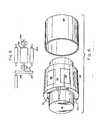
- the final assembly step is to install the outer shell 90 onto the rotor assembly 100, as shown in FIGURE 6.
- the outer shell is typically non-magnetic steel such as INCO-718, a material which is both extremely strong and non-magnetic. Another material which may be used for the shell 90 in certain applications is berillium-copper.
- the shell 90 thickness is kept to a minimum to keep the distance between the magnets 80 and a stator 300 of the device ( Figure 8) as small as possible.
- the shell 90 thickness may vary from .1 cms to .7 cms. Factors in determining the required shell thickness include the diameter of the rotor assembly 100, the speed at which the device will operate and the related centrifugal force operating on the rotor assembly 100.
- the shell 90 is an interference fit on the rotor assembly 100.
- the preferred method for installation is to put the rotor assembly 100 in dry ice, to heat the shell 90 and immediately install the shell. 90 onto the rotor assembly 100.
- the shell 90 is then immediately cooled by directing water onto the shell 90 and the rotor assembly 100 to reduce the possibility of heat damage to the magnets 80.
- the rotor assembly 100 and the shell 90 may then be balanced by drilling holes 110 in the side of the aluminium casting portion 60 of the rotor assembly 100.
- FIGURE 7 shows a rotor assembly 200 containing three separate sets of magnets which may be manufactured according to the present invention.
- the rotor assembly 200 is covered with a shell 190.
- Such a rotor assembly containing multiple sets of magnets is virtually impossible to manufacture utilising the spacer and ring technique, but is quite simple to manufacture using the teachings of the present invention.
- the resulting rotor assembly 200 has sufficient shaft stiffness to ensure that the flexure critical speed is above the desired operating speed.
- the preferred technique is to die cast the aluminium coating 60 onto the shaft 10.
- the die (not shown) is constructed so that it has retractable blocks, and when the shaft 10 is mounted in the die, the blocks are moved inwardly adjacent the flat surfaces 30 on the shaft 10.
- the molten aluminium is then injected into the die, and the retractable blocks are removed from the die, which may then be opened to remove the shaft 10 containing the aluminium coating 60.
- the device is then machined and finished exactly as described above.
- a rotor constructed according to the teachings of this disclosure is in a turboalternator, that is, a rotor assembly 250 driven at high speed by a turbine wheel 260, as illustrated in FIGURE 8.
- the rotor assembly 250 is supported by bearings 270 and 280, and is connected to, and drives,the turbine wheel 260.
- a nozzle 290 directs hot gas onto the turbine wheel 260.
- the stator 300 is mounted around the rotor assembly 250.
- a rotor assembly manufactured according to the above teachings is not very susceptible to excess heat buildup in the magnets, thus effectively eliminating failure of the device due to destruction of the permanent magnets. Since rings and spacers are eliminated by the casting of aluminium directly onto the steel shaft, the requirements of high tolerance machining of components is substantially reduced, along with the high rejection rate of rotors with components not fitting properly. The re-sulting rotor has excellent rigidity, even allowing for multiple sets of magnets on a single shaft. Finally, the manufacturing technique taught herein substantially reduces the cost of manufacturing rotor assemblies, while resulting in rotor assemblies having uniform high quality.
Landscapes
- Engineering & Computer Science (AREA)
- Power Engineering (AREA)
- Manufacturing & Machinery (AREA)
- Manufacture Of Motors, Generators (AREA)
- Permanent Field Magnets Of Synchronous Machinery (AREA)
- Iron Core Of Rotating Electric Machines (AREA)
Applications Claiming Priority (2)
| Application Number | Priority Date | Filing Date | Title |
|---|---|---|---|
| US515331 | 1983-07-19 | ||
| US06/515,331 US4549341A (en) | 1983-07-19 | 1983-07-19 | Method for producing a permanent magnet rotor |
Publications (2)
| Publication Number | Publication Date |
|---|---|
| EP0134670A1 true EP0134670A1 (fr) | 1985-03-20 |
| EP0134670B1 EP0134670B1 (fr) | 1988-06-01 |
Family
ID=24050909
Family Applications (1)
| Application Number | Title | Priority Date | Filing Date |
|---|---|---|---|
| EP84304861A Expired EP0134670B1 (fr) | 1983-07-19 | 1984-07-17 | Méthode de fabrication d'un rotor à aimant permanent |
Country Status (5)
| Country | Link |
|---|---|
| US (1) | US4549341A (fr) |
| EP (1) | EP0134670B1 (fr) |
| JP (1) | JPS6035939A (fr) |
| CA (1) | CA1205506A (fr) |
| DE (1) | DE3471848D1 (fr) |
Cited By (13)
| Publication number | Priority date | Publication date | Assignee | Title |
|---|---|---|---|---|
| EP0187478A1 (fr) * | 1984-12-06 | 1986-07-16 | AlliedSignal Inc. | Rotor à aimant permanent p. ex. pour générateurs et procédé d'assemblage |
| GB2172443A (en) * | 1985-03-13 | 1986-09-17 | Dowty Fuel Syst Ltd | Electrical machines |
| EP0212552A3 (en) * | 1985-08-14 | 1987-05-13 | Kollmorgen Technologies Corporation | Composite sleeve for an electric motor and method for producing same |
| FR2606949A1 (fr) * | 1986-11-14 | 1988-05-20 | Ragonot Ind Sa | Rotor a aimants permanents pour moteur electrique, et moteur muni d'un tel rotor |
| WO1998033260A1 (fr) * | 1997-01-24 | 1998-07-30 | Commonwealth Scientific And Industrial Research Organisation | Electromoteurs tres rapides ameliores |
| WO1998034324A1 (fr) * | 1997-01-29 | 1998-08-06 | Turbocorp Limited | Perfectionnements concernant les arbres de rotors grande vitesse |
| DE19846924A1 (de) * | 1998-10-12 | 2000-04-13 | Sachsenwerk Gmbh | Permanentmagneterregte Baugruppe einer elektrischen Maschine und Verfahren zu ihrer Herstellung |
| AU735783B2 (en) * | 1997-01-29 | 2001-07-12 | Danfoss A/S | Improvements in high speed rotor shafts |
| AU743860B2 (en) * | 1997-01-24 | 2002-02-07 | Danfoss A/S | Improvements in high speed electric motors |
| GB2388479B (en) * | 2002-04-26 | 2007-01-03 | Bowman Power Systems Ltd | Rotors for electromagnetic machines |
| US8343572B2 (en) | 2007-08-13 | 2013-01-01 | Ashish Varade | Composition of electrode material in the form of a coating and a process thereof |
| EP3422540A1 (fr) * | 2017-06-06 | 2019-01-02 | Simeti Group Limited | Procédé de collage d'aimants segmentés à l'enveloppe intérieure d'un corps de rotor et équipement permettant de mettre en oeuvre ce procédé |
| WO2022048831A1 (fr) * | 2020-09-04 | 2022-03-10 | Sew-Eurodrive Gmbh & Co. Kg | Moteur électrique à rotor |
Families Citing this family (39)
| Publication number | Priority date | Publication date | Assignee | Title |
|---|---|---|---|---|
| US4930201A (en) * | 1985-08-14 | 1990-06-05 | Kollmorgen Corporation | Method for manufacturing a composite sleeve for an electric motor |
| US4777397A (en) * | 1986-08-15 | 1988-10-11 | Marathon Electric Manufacturing Corp. | Permanent magnet generator apparatus including a consequent pole rotor |
| JPH0832147B2 (ja) * | 1986-11-21 | 1996-03-27 | 株式会社芝浦製作所 | 電動機の製造方法 |
| JPS63198776A (ja) * | 1987-02-12 | 1988-08-17 | Nissan Motor Co Ltd | 内燃機関用始動電動機 |
| US5065063A (en) * | 1988-03-30 | 1991-11-12 | Aisin Seiki Kabushiki Kaisha | Rotating apparatus |
| US4855630A (en) * | 1988-05-05 | 1989-08-08 | A. O. Smith Corporation | Permanent magnet rotor with magnet retention band |
| US4920634A (en) * | 1988-05-05 | 1990-05-01 | A. O. Smith Corporation | Permanent magnet rotor with magnet retention band |
| US5345669A (en) * | 1988-06-08 | 1994-09-13 | General Electric Company | Method of making a permanent magnet rotor |
| US5237737A (en) * | 1988-06-08 | 1993-08-24 | General Electric Company | Method of making a permanent magnet rotor |
| US5563463A (en) * | 1988-06-08 | 1996-10-08 | General Electric Company | Permanent magnet rotor |
| US5144735A (en) * | 1988-06-08 | 1992-09-08 | General Electric Company | Apparatus for assembling a permanent magnet rotor |
| US5040286A (en) * | 1988-06-08 | 1991-08-20 | General Electric Company | Method for making permanent magnet rotor |
| JPH0417537A (ja) * | 1990-05-11 | 1992-01-22 | Daikin Ind Ltd | 電動機の回転子 |
| US5166569A (en) * | 1990-12-04 | 1992-11-24 | Sundstrand Corporation | Rotor containment assembly for dynamoelectric machines |
| JPH04364346A (ja) * | 1991-06-11 | 1992-12-16 | Mitsubishi Electric Corp | 車両用交流発電機の回転子のバランス調整方法 |
| GB9510994D0 (en) * | 1995-05-31 | 1995-07-26 | Turbo Genset The Company Ltd | Rotary electrical machines |
| US5758709A (en) * | 1995-12-04 | 1998-06-02 | General Electric Company | Method of fabricating a rotor for an electric motor |
| FR2744854B1 (fr) * | 1996-02-08 | 1998-03-13 | Gec Alsthom Moteurs Sa | Procede de fabrication d'un rotor magnetoelectrique a griffes, rotor fabrique par un tel procede |
| FR2746558B1 (fr) * | 1996-03-22 | 1998-04-24 | Gec Alsthom Moteurs Sa | Rotor magnetoelectrique a griffes, procede de fabrication d'un tel rotor |
| JP2992265B2 (ja) * | 1997-04-29 | 1999-12-20 | エルジー電子株式会社 | 圧縮機用モータのマグネット配設構造 |
| KR19990048726A (ko) * | 1997-12-10 | 1999-07-05 | 구자홍 | 리니어 모터의 마그네트 고정구조 |
| US6481090B1 (en) * | 2001-06-25 | 2002-11-19 | Electric Boat Corporation | Installation and removal of energized permanent magnets in permanent magnet rotors |
| JP2005328601A (ja) * | 2004-05-13 | 2005-11-24 | Minebea Co Ltd | 電動シャッター又は電動ブラインド用チューブモータ |
| DE602005018605D1 (de) * | 2005-04-22 | 2010-02-11 | Infranor Holding S A | System zur Befestigung von Dauermagneten |
| US7183683B2 (en) * | 2005-06-23 | 2007-02-27 | Peopleflo Manufacturing Inc. | Inner magnet of a magnetic coupling |
| US7549205B2 (en) * | 2005-06-24 | 2009-06-23 | Peopleflo Manufacturing Inc. | Assembly and method for pre-stressing a magnetic coupling canister |
| US20070138891A1 (en) * | 2005-12-19 | 2007-06-21 | Emerson Electric Co. | Magnet retention and positioning sleeve for surface mounted rotor assemblies |
| US7673380B2 (en) | 2007-04-23 | 2010-03-09 | Varco I/P, Inc. | Methods for making rotors for permanent magnet motors |
| BE1018010A3 (nl) | 2008-06-13 | 2010-03-02 | Atlas Copco Airpower Nv | Werkwijze voor het met een klempassing monteren van een bus rond een gedeelte van een as. |
| CN102946173B (zh) * | 2012-09-25 | 2015-01-07 | 宁波菲仕运动控制技术有限公司 | 一种磁瓦外套热压工装 |
| US20140140857A1 (en) * | 2012-11-20 | 2014-05-22 | Turbogen, Llc | Rotor assembly and method of using same |
| US20150022041A1 (en) * | 2013-07-18 | 2015-01-22 | Honeywell International Inc. | Method of cooling a generator or motor rotor with end disks and a hybrid shaft assembly |
| US10267315B2 (en) * | 2013-11-28 | 2019-04-23 | Acd, Llc | Cryogenic submerged pump for LNG, light hydrocarbon and other electrically non-conducting and non-corrosive fluids |
| CN106233581A (zh) * | 2014-02-03 | 2016-12-14 | 坎里格钻探技术有限公司 | 电动机中永磁体的联接 |
| US20150333584A1 (en) * | 2014-05-15 | 2015-11-19 | Calnetix Technologies, Llc | High speed brushless dc electric machine |
| US10742082B2 (en) * | 2014-12-31 | 2020-08-11 | Ingersoll-Rand Industrial U.S., Inc. | Fixation system for a permanent magnet rotor |
| US11364757B2 (en) | 2019-06-28 | 2022-06-21 | Ree Automotive Ltd | Device and method for double-arm suspension and in-wheel steering |
| US11480032B2 (en) * | 2020-03-02 | 2022-10-25 | Weatherford Technology Holdings, Llc | Debris collection tool |
| EP4037158B1 (fr) | 2021-02-02 | 2025-07-30 | Black & Decker, Inc. | Moteur sans balai comprenant un pont de palier imbriqué |
Citations (5)
| Publication number | Priority date | Publication date | Assignee | Title |
|---|---|---|---|---|
| FR1237215A (fr) * | 1959-06-16 | 1960-07-29 | Fr D App De Prec Soc | Rotor multipolaire pour générateur magnéto-électrique |
| FR2457031A1 (fr) * | 1979-05-15 | 1980-12-12 | Lucas Industries Ltd | Procede d'assemblage d'un rotor a aimants permanents |
| DE8031234U1 (de) * | 1980-11-24 | 1981-04-02 | Siemens AG, 1000 Berlin und 8000 München | Dauermagneterregter laeufer fuer eine elektrische maschine |
| FR2503950A1 (fr) * | 1981-04-10 | 1982-10-15 | Goig Florencio | Perfectionnements apportes aux rotors notamment pour l'excitation d'alternateurs destines a l'allumage de moteurs pour vehicules a deux roues ou plus de deux roues |
| GB2117188A (en) * | 1982-03-24 | 1983-10-05 | Okuma Machinery Works Ltd | A permanent magnet rotor for synchronous motors |
Family Cites Families (18)
| Publication number | Priority date | Publication date | Assignee | Title |
|---|---|---|---|---|
| US1535330A (en) * | 1919-07-17 | 1925-04-28 | Sperry Gyroscope Co Ltd | Method of centrifugal casting |
| US3083311A (en) * | 1956-11-08 | 1963-03-26 | Krasnow Shelley | Converters and circuits for high frequency fluorescent lighting |
| US2432436A (en) * | 1943-09-16 | 1947-12-09 | Wayne J Morrill | Permanent magnet rotor |
| US2571318A (en) * | 1944-07-07 | 1951-10-16 | Borg Warner | Fabricated splined shaft |
| US2493102A (en) * | 1946-12-26 | 1950-01-03 | Keefe And Merritt Company O | Rotor for electric machines and method of making the same |
| US2475776A (en) * | 1947-01-11 | 1949-07-12 | Keefe And Merritt Company O | Rotor for dynamoelectric machines |
| US2504823A (en) * | 1948-03-24 | 1950-04-18 | Allis Chalmers Mfg Co | Die cast rotor with tubular inserts embedden in destructible material |
| GB763094A (en) * | 1954-02-09 | 1956-12-05 | British Thomson Houston Co Ltd | Improvements relating to magneto electric machines |
| DE1093000B (de) * | 1956-03-23 | 1960-11-17 | Wipac Dev Ltd | Schwungradlaeufer fuer elektrische Stromerzeuger mit mehreren Dauermagneten |
| US3132270A (en) * | 1959-09-29 | 1964-05-05 | Phelon Co Inc | Rotor annulus for electric generator |
| US3077026A (en) * | 1959-11-12 | 1963-02-12 | Gen Motors Corp | Method of making a permanent magnet rotor |
| US3368275A (en) * | 1962-07-03 | 1968-02-13 | Syncro Corp | Casting, machining, and assembling a magnetic motor ring structure |
| US3292126A (en) * | 1964-08-24 | 1966-12-13 | Buck Mfg Company | Permanent magnet pulley |
| US3531670A (en) * | 1968-09-16 | 1970-09-29 | Bendix Corp | Rotary electrical apparatus having metallic sleeve for embracing the peripheral sections of permanent magnet rotor |
| US3581394A (en) * | 1969-05-13 | 1971-06-01 | Russell E Phelon | Rotor annulus for electric generator |
| US3979821A (en) * | 1975-05-09 | 1976-09-14 | Kollmorgen Corporation | Method of manufacturing rare earth permanent magnet rotor |
| US4011120A (en) * | 1975-05-02 | 1977-03-08 | Tecumseh Products Company | Method for fastening ceramic magnets to a flywheel using centrifugal force |
| EP0013157B1 (fr) * | 1978-12-26 | 1986-10-15 | The Garrett Corporation | Rotors à aimant permanent, notamment pour machines dynamo-électriques |
-
1983
- 1983-07-19 US US06/515,331 patent/US4549341A/en not_active Expired - Lifetime
-
1984
- 1984-06-05 CA CA000455883A patent/CA1205506A/fr not_active Expired
- 1984-07-17 EP EP84304861A patent/EP0134670B1/fr not_active Expired
- 1984-07-17 DE DE8484304861T patent/DE3471848D1/de not_active Expired
- 1984-07-18 JP JP59147729A patent/JPS6035939A/ja active Pending
Patent Citations (5)
| Publication number | Priority date | Publication date | Assignee | Title |
|---|---|---|---|---|
| FR1237215A (fr) * | 1959-06-16 | 1960-07-29 | Fr D App De Prec Soc | Rotor multipolaire pour générateur magnéto-électrique |
| FR2457031A1 (fr) * | 1979-05-15 | 1980-12-12 | Lucas Industries Ltd | Procede d'assemblage d'un rotor a aimants permanents |
| DE8031234U1 (de) * | 1980-11-24 | 1981-04-02 | Siemens AG, 1000 Berlin und 8000 München | Dauermagneterregter laeufer fuer eine elektrische maschine |
| FR2503950A1 (fr) * | 1981-04-10 | 1982-10-15 | Goig Florencio | Perfectionnements apportes aux rotors notamment pour l'excitation d'alternateurs destines a l'allumage de moteurs pour vehicules a deux roues ou plus de deux roues |
| GB2117188A (en) * | 1982-03-24 | 1983-10-05 | Okuma Machinery Works Ltd | A permanent magnet rotor for synchronous motors |
Non-Patent Citations (1)
| Title |
|---|
| PATENT ABSTRACTS OF JAPAN, vol. 5, no. 125, 12 August 1981, & JP-A-56-62054 (HITACHI SEISAKUSHO K.K.) 27-05-1981 * |
Cited By (14)
| Publication number | Priority date | Publication date | Assignee | Title |
|---|---|---|---|---|
| EP0187478A1 (fr) * | 1984-12-06 | 1986-07-16 | AlliedSignal Inc. | Rotor à aimant permanent p. ex. pour générateurs et procédé d'assemblage |
| GB2172443A (en) * | 1985-03-13 | 1986-09-17 | Dowty Fuel Syst Ltd | Electrical machines |
| EP0212552A3 (en) * | 1985-08-14 | 1987-05-13 | Kollmorgen Technologies Corporation | Composite sleeve for an electric motor and method for producing same |
| FR2606949A1 (fr) * | 1986-11-14 | 1988-05-20 | Ragonot Ind Sa | Rotor a aimants permanents pour moteur electrique, et moteur muni d'un tel rotor |
| AU743860B2 (en) * | 1997-01-24 | 2002-02-07 | Danfoss A/S | Improvements in high speed electric motors |
| US6194852B1 (en) | 1997-01-24 | 2001-02-27 | Commonwealth Scientific And Industrial Research Organisation | High speed electric motors |
| WO1998033260A1 (fr) * | 1997-01-24 | 1998-07-30 | Commonwealth Scientific And Industrial Research Organisation | Electromoteurs tres rapides ameliores |
| WO1998034324A1 (fr) * | 1997-01-29 | 1998-08-06 | Turbocorp Limited | Perfectionnements concernant les arbres de rotors grande vitesse |
| AU735783B2 (en) * | 1997-01-29 | 2001-07-12 | Danfoss A/S | Improvements in high speed rotor shafts |
| DE19846924A1 (de) * | 1998-10-12 | 2000-04-13 | Sachsenwerk Gmbh | Permanentmagneterregte Baugruppe einer elektrischen Maschine und Verfahren zu ihrer Herstellung |
| GB2388479B (en) * | 2002-04-26 | 2007-01-03 | Bowman Power Systems Ltd | Rotors for electromagnetic machines |
| US8343572B2 (en) | 2007-08-13 | 2013-01-01 | Ashish Varade | Composition of electrode material in the form of a coating and a process thereof |
| EP3422540A1 (fr) * | 2017-06-06 | 2019-01-02 | Simeti Group Limited | Procédé de collage d'aimants segmentés à l'enveloppe intérieure d'un corps de rotor et équipement permettant de mettre en oeuvre ce procédé |
| WO2022048831A1 (fr) * | 2020-09-04 | 2022-03-10 | Sew-Eurodrive Gmbh & Co. Kg | Moteur électrique à rotor |
Also Published As
| Publication number | Publication date |
|---|---|
| JPS6035939A (ja) | 1985-02-23 |
| DE3471848D1 (en) | 1988-07-07 |
| US4549341A (en) | 1985-10-29 |
| EP0134670B1 (fr) | 1988-06-01 |
| CA1205506A (fr) | 1986-06-03 |
Similar Documents
| Publication | Publication Date | Title |
|---|---|---|
| EP0134670B1 (fr) | Méthode de fabrication d'un rotor à aimant permanent | |
| US4625135A (en) | Permanent magnet rotor | |
| US5220233A (en) | Dynamoelectric machines | |
| US4691131A (en) | Stator laminate impregnation in a liquid-cooled motor | |
| US4667123A (en) | Two pole permanent magnet rotor construction for toothless stator electrical machine | |
| US5334899A (en) | Polyphase brushless DC and AC synchronous machines | |
| US5021698A (en) | Axial field electrical generator | |
| US7042118B2 (en) | Permanent magnet rotor construction wherein relative movement between components is prevented | |
| US4617726A (en) | Maximum stiffness permanent magnet rotor and construction method | |
| EP0341317A1 (fr) | Structure de rotor pour moteur a induction a grande vitesse | |
| US8946969B2 (en) | Rotor of an asynchronous machine with retaining element | |
| CN109155576B (zh) | 水力发电机和用于制造和运行水力发电机的方法 | |
| US5592039A (en) | AC and DC motor-generator set having stators with annular end plate water cooling channels | |
| CN110932438A (zh) | 具有端轴的用于异步电力机器的转子 | |
| CA2284249A1 (fr) | Procede et appareil de reduction de pertes par ventilation dans un equipement rotatif et moteur/generateur electrique utilisant cet appareil | |
| JP2709403B2 (ja) | 回転式電気機械 | |
| CN112974867A (zh) | 一种气浮电主轴和钻机 | |
| US3191079A (en) | Heavy dynamoelectric machine having nylon bearings | |
| WO2019116389A1 (fr) | Stator unitaire, rotor fendu et leur dispositif à réluctance commutée | |
| EP3635847B1 (fr) | Broches d'usinage équipées de moteurs à induction à courant alternatif et arbres destinés à de telles broches | |
| JP2004516795A (ja) | 発電機ロータコイル端の冷却を増大させるための高熱伝導性スペースブロック | |
| CA1194915A (fr) | Rotor pour dispositifs electromagnetiques a champ axial et methodes de fabrication | |
| GB2338350A (en) | Cooling laminated assemblies of electrical rotating machines | |
| CN113424399A (zh) | 用于环形电机的转子、相应的环形电机和制造转子的方法 | |
| KR100317141B1 (ko) | 고투자율 분말이 함유된 고분자 수지를 이용한 농형 회전자 |
Legal Events
| Date | Code | Title | Description |
|---|---|---|---|
| PUAI | Public reference made under article 153(3) epc to a published international application that has entered the european phase |
Free format text: ORIGINAL CODE: 0009012 |
|
| AK | Designated contracting states |
Designated state(s): CH DE FR GB IT LI SE |
|
| 17P | Request for examination filed |
Effective date: 19850917 |
|
| 17Q | First examination report despatched |
Effective date: 19860606 |
|
| ITF | It: translation for a ep patent filed | ||
| GRAA | (expected) grant |
Free format text: ORIGINAL CODE: 0009210 |
|
| AK | Designated contracting states |
Kind code of ref document: B1 Designated state(s): CH DE FR GB IT LI SE |
|
| REF | Corresponds to: |
Ref document number: 3471848 Country of ref document: DE Date of ref document: 19880707 |
|
| ET | Fr: translation filed | ||
| PLBE | No opposition filed within time limit |
Free format text: ORIGINAL CODE: 0009261 |
|
| STAA | Information on the status of an ep patent application or granted ep patent |
Free format text: STATUS: NO OPPOSITION FILED WITHIN TIME LIMIT |
|
| 26N | No opposition filed | ||
| PGFP | Annual fee paid to national office [announced via postgrant information from national office to epo] |
Ref country code: CH Payment date: 19890814 Year of fee payment: 6 |
|
| PG25 | Lapsed in a contracting state [announced via postgrant information from national office to epo] |
Ref country code: LI Effective date: 19900731 Ref country code: CH Effective date: 19900731 |
|
| REG | Reference to a national code |
Ref country code: CH Ref legal event code: PL |
|
| ITTA | It: last paid annual fee | ||
| PGFP | Annual fee paid to national office [announced via postgrant information from national office to epo] |
Ref country code: GB Payment date: 19920706 Year of fee payment: 9 |
|
| PGFP | Annual fee paid to national office [announced via postgrant information from national office to epo] |
Ref country code: FR Payment date: 19920707 Year of fee payment: 9 |
|
| PGFP | Annual fee paid to national office [announced via postgrant information from national office to epo] |
Ref country code: SE Payment date: 19920713 Year of fee payment: 9 |
|
| PGFP | Annual fee paid to national office [announced via postgrant information from national office to epo] |
Ref country code: DE Payment date: 19920727 Year of fee payment: 9 |
|
| PG25 | Lapsed in a contracting state [announced via postgrant information from national office to epo] |
Ref country code: GB Effective date: 19930717 |
|
| PG25 | Lapsed in a contracting state [announced via postgrant information from national office to epo] |
Ref country code: SE Effective date: 19930718 |
|
| GBPC | Gb: european patent ceased through non-payment of renewal fee |
Effective date: 19930717 |
|
| PG25 | Lapsed in a contracting state [announced via postgrant information from national office to epo] |
Ref country code: FR Effective date: 19940331 |
|
| PG25 | Lapsed in a contracting state [announced via postgrant information from national office to epo] |
Ref country code: DE Effective date: 19940401 |
|
| REG | Reference to a national code |
Ref country code: FR Ref legal event code: ST |
|
| EUG | Se: european patent has lapsed |
Ref document number: 84304861.2 Effective date: 19940210 |