EP0137659A2 - Geschwindigkeits-Lage-Servomechanismus mit Verstärkungssteuerung - Google Patents
Geschwindigkeits-Lage-Servomechanismus mit Verstärkungssteuerung Download PDFInfo
- Publication number
- EP0137659A2 EP0137659A2 EP84305614A EP84305614A EP0137659A2 EP 0137659 A2 EP0137659 A2 EP 0137659A2 EP 84305614 A EP84305614 A EP 84305614A EP 84305614 A EP84305614 A EP 84305614A EP 0137659 A2 EP0137659 A2 EP 0137659A2
- Authority
- EP
- European Patent Office
- Prior art keywords
- servo
- mode
- gain
- velocity
- relatively high
- Prior art date
- Legal status (The legal status is an assumption and is not a legal conclusion. Google has not performed a legal analysis and makes no representation as to the accuracy of the status listed.)
- Granted
Links
Images
Classifications
-
- G—PHYSICS
- G05—CONTROLLING; REGULATING
- G05B—CONTROL OR REGULATING SYSTEMS IN GENERAL; FUNCTIONAL ELEMENTS OF SUCH SYSTEMS; MONITORING OR TESTING ARRANGEMENTS FOR SUCH SYSTEMS OR ELEMENTS
- G05B19/00—Program-control systems
- G05B19/02—Program-control systems electric
- G05B19/18—Numerical control [NC], i.e. automatically operating machines, in particular machine tools, e.g. in a manufacturing environment, so as to execute positioning, movement or co-ordinated operations by means of program data in numerical form
- G05B19/19—Numerical control [NC], i.e. automatically operating machines, in particular machine tools, e.g. in a manufacturing environment, so as to execute positioning, movement or co-ordinated operations by means of program data in numerical form characterised by positioning or contouring control systems, e.g. to control position from one programmed point to another or to control movement along a programmed continuous path
- G05B19/39—Numerical control [NC], i.e. automatically operating machines, in particular machine tools, e.g. in a manufacturing environment, so as to execute positioning, movement or co-ordinated operations by means of program data in numerical form characterised by positioning or contouring control systems, e.g. to control position from one programmed point to another or to control movement along a programmed continuous path using a combination of the means covered by at least two of the preceding groups G05B19/21, G05B19/27 and G05B19/33
-
- B—PERFORMING OPERATIONS; TRANSPORTING
- B41—PRINTING; LINING MACHINES; TYPEWRITERS; STAMPS
- B41J—TYPEWRITERS; SELECTIVE PRINTING MECHANISMS, i.e. MECHANISMS PRINTING OTHERWISE THAN FROM A FORME; CORRECTION OF TYPOGRAPHICAL ERRORS
- B41J1/00—Typewriters or selective printing mechanisms characterised by the mounting, arrangement or disposition of the types or dies
- B41J1/22—Typewriters or selective printing mechanisms characterised by the mounting, arrangement or disposition of the types or dies with types or dies mounted on carriers rotatable for selection
- B41J1/24—Typewriters or selective printing mechanisms characterised by the mounting, arrangement or disposition of the types or dies with types or dies mounted on carriers rotatable for selection the plane of the type or die face being perpendicular to the axis of rotation
- B41J1/28—Carriers stationary for impression, e.g. with the types or dies not moving relative to the carriers
- B41J1/30—Carriers stationary for impression, e.g. with the types or dies not moving relative to the carriers with the types or dies moving relative to the carriers or mounted on flexible carriers
-
- G—PHYSICS
- G05—CONTROLLING; REGULATING
- G05B—CONTROL OR REGULATING SYSTEMS IN GENERAL; FUNCTIONAL ELEMENTS OF SUCH SYSTEMS; MONITORING OR TESTING ARRANGEMENTS FOR SUCH SYSTEMS OR ELEMENTS
- G05B2219/00—Program-control systems
- G05B2219/30—Nc systems
- G05B2219/41—Servomotor, servo controller till figures
- G05B2219/41021—Variable gain
-
- G—PHYSICS
- G05—CONTROLLING; REGULATING
- G05B—CONTROL OR REGULATING SYSTEMS IN GENERAL; FUNCTIONAL ELEMENTS OF SUCH SYSTEMS; MONITORING OR TESTING ARRANGEMENTS FOR SUCH SYSTEMS OR ELEMENTS
- G05B2219/00—Program-control systems
- G05B2219/30—Nc systems
- G05B2219/42—Servomotor, servo controller kind till VSS
- G05B2219/42104—Loop switch, speed loop then position loop, mode switch
-
- G—PHYSICS
- G05—CONTROLLING; REGULATING
- G05B—CONTROL OR REGULATING SYSTEMS IN GENERAL; FUNCTIONAL ELEMENTS OF SUCH SYSTEMS; MONITORING OR TESTING ARRANGEMENTS FOR SUCH SYSTEMS OR ELEMENTS
- G05B2219/00—Program-control systems
- G05B2219/30—Nc systems
- G05B2219/45—Nc applications
- G05B2219/45187—Printer
Definitions
- This invention relates to servo control systems for use in electro-mechanical printing devices of the type employing a rotary print wheel, sometimes termed a “daisy wheel printer", wherein the print wheel is both rotated and translated by a pair of motors under control of an electronic control system.
- position feedback signals generated by a position encoder associated to the controlled element are used to provide the necessary feedback information specifying the instantaneous position of the controlled element.
- These signals are coupled to a control unit in which the position information is used to determine certain key parameters, -such as direction of print wheel rotation, incremental linear or angular distance from the present position to the next desired position, actual velocity of the controlled element, required incremental velocity, and the like.
- the control unit supervises the operating mode of each servo system, i.e., whether velocity or position mode, and generates the necessary servo control signals for switching the operationbetween the- two distinct modes.
- the servo system uses one of the analog position feedback signals to monitor excursions of the controlled element away from the desired HOME position in order to generate corrective position signals to the motor driving the controlled element in order to counteract any such deviations.
- the invention comprises a method of operating a rotary printer dual mode servo system having a velocity mode and a position mode, the method comprising the steps of operating the servo system in the velocity mode with a first relatively high gain, switching the servo system to the position mode, operating the servo system in the position mode at the relatively high gain for a maximum predetermined time period, and reducing the gain of the servo system to a relatively low value whenever the maximum predetermined time period has elapsed without resumption of the velocity mode.
- the step of reducing the gain of the servo system includes the step of inserting a second R-C network into the gain establishing network of the system.
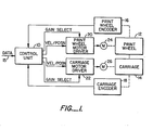
- Fig. 1 illustrates in block diagram form a rotary printer control system incorporating the invention.
- a control unit 10 for a rotary print wheel schematically depicted as element 12 and a print wheel and hammer carriage, schematically depicted as element 14, receives data signals via a data input line 15 specifying the text content to be printed.
- the source of such data on input conductor 15 may be a typewriter keyboard, an associated word processing computer, a remote computer or the like.
- the print wheel motor driver 20 and carriage motor driver 22 are similar units which generate, in response to input velocity/position control signals, appropriate driving currents for their respective associated motors 24 and 26, so that the print wheel 12 and carriage 14 are respectively rotated and translated at the proper design velocities (when the servo is operated in the velocity mode) and maintained in a relatively stationary position when the HOME position is achieved (when the servo is operated in the position mode).
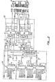
- the print wheel motor driver 20, and carriage motor driver 22 are illustrated in detail and are seen to comprise a pair of identical type L292 motor driver units available from SGS of Scottsdale, Arizona.
- the relatively high gain operation of the upper motor driver is provided by an R-C network comprising resistor 31 and capacitor 32, and a similar R-C network comprising resistor 35 and capacitor 36 is used to provide a similar relatively high gain value for the lower motor driver.
- the reduction in gain to the relatively low value is accomplished by switching in an additional R-C network in parallel with the permanently connected R-C network in response to the GAIN signal.
- an analog position signal A generated by tachometer 61 from the PWA input signal is coupled through FET switch 71 and summed with the velocity signal output from tachometer 61 to maintain the print wheel 12 in the HOME position.
- the operation of the carriage motor servo is identical in operation to that described above, with lower FET switches 73, 74 being used for the desired carriage velocity and desired carriage position signal summing with the actual carriage velocity signal.
Landscapes
- Engineering & Computer Science (AREA)
- Human Computer Interaction (AREA)
- Manufacturing & Machinery (AREA)
- Physics & Mathematics (AREA)
- General Physics & Mathematics (AREA)
- Automation & Control Theory (AREA)
- Character Spaces And Line Spaces In Printers (AREA)
- Control Of Electric Motors In General (AREA)
- Control Of Position Or Direction (AREA)
Priority Applications (1)
| Application Number | Priority Date | Filing Date | Title |
|---|---|---|---|
| AT84305614T ATE38184T1 (de) | 1983-09-27 | 1984-08-17 | Geschwindigkeits-lage-servomechanismus mit verstaerkungssteuerung. |
Applications Claiming Priority (2)
| Application Number | Priority Date | Filing Date | Title |
|---|---|---|---|
| US536553 | 1983-09-27 | ||
| US06/536,553 US4551664A (en) | 1983-09-27 | 1983-09-27 | Velocity-position servo with improved gain control |
Publications (3)
| Publication Number | Publication Date |
|---|---|
| EP0137659A2 true EP0137659A2 (de) | 1985-04-17 |
| EP0137659A3 EP0137659A3 (en) | 1985-07-17 |
| EP0137659B1 EP0137659B1 (de) | 1988-10-26 |
Family
ID=24138981
Family Applications (1)
| Application Number | Title | Priority Date | Filing Date |
|---|---|---|---|
| EP84305614A Expired EP0137659B1 (de) | 1983-09-27 | 1984-08-17 | Geschwindigkeits-Lage-Servomechanismus mit Verstärkungssteuerung |
Country Status (6)
| Country | Link |
|---|---|
| US (1) | US4551664A (de) |
| EP (1) | EP0137659B1 (de) |
| JP (1) | JPS60109843A (de) |
| KR (1) | KR860002200B1 (de) |
| AT (1) | ATE38184T1 (de) |
| DE (1) | DE3474791D1 (de) |
Cited By (1)
| Publication number | Priority date | Publication date | Assignee | Title |
|---|---|---|---|---|
| EP0260138A3 (en) * | 1986-09-10 | 1989-05-31 | Fujitsu Limited | Servo control system |
Families Citing this family (11)
| Publication number | Priority date | Publication date | Assignee | Title |
|---|---|---|---|---|
| US4721895A (en) * | 1983-11-22 | 1988-01-26 | Qume Corporation | Multi-speed analog servo |
| GB2164152B (en) * | 1984-06-02 | 1988-07-06 | Citizen Watch Co Ltd | Physical quantity indicating device by a pointer |
| US4710865A (en) * | 1984-11-14 | 1987-12-01 | Canon Kabushiki Kaisha | Control system for positioning an object using switching from a speed control mode to a position control mode with adjustable brain |
| US4810941A (en) * | 1986-04-17 | 1989-03-07 | Canon Kabushiki Kaisha | Control system for a servomotor |
| JP3832712B2 (ja) * | 2000-09-21 | 2006-10-11 | セイコーエプソン株式会社 | 印刷制御装置および制御方法ならびに印刷制御プログラムを記録した記録媒体 |
| US6940252B2 (en) * | 2001-01-31 | 2005-09-06 | Canon Kabushiki Kaisha | DC motor control method and apparatus |
| JP3658339B2 (ja) * | 2001-05-17 | 2005-06-08 | キヤノン株式会社 | モータの制御のための方法及び装置 |
| US6611119B2 (en) * | 2001-08-30 | 2003-08-26 | Lockheed Martin Corporation | Switching processes for control of servos |
| US6707269B2 (en) * | 2001-09-11 | 2004-03-16 | Seagate Technology Llc | Motor control circuit with adaptive dynamic range selection |
| JP4666970B2 (ja) * | 2004-07-28 | 2011-04-06 | キヤノン株式会社 | 搬送装置及び該装置を備えた記録装置 |
| US9211741B2 (en) * | 2012-07-17 | 2015-12-15 | Hewlett-Packard Development Company, L.P. | Position encoder systems |
Family Cites Families (6)
| Publication number | Priority date | Publication date | Assignee | Title |
|---|---|---|---|---|
| US3721882A (en) * | 1971-06-25 | 1973-03-20 | Sperry Rand Corp | Positioning system |
| US4021650A (en) * | 1975-11-19 | 1977-05-03 | Xerox Corporation | Velocity command signal generating apparatus |
| JPS53141724A (en) * | 1977-05-16 | 1978-12-09 | Fujitsu Ltd | Type selector for serial printer |
| US4293233A (en) * | 1978-12-06 | 1981-10-06 | Sci Systems, Inc. | Printer control system |
| JPS56119349A (en) * | 1980-02-23 | 1981-09-18 | Fanuc Ltd | Controlling device of main shaft orientation |
| US4486693A (en) * | 1982-07-06 | 1984-12-04 | Contitronix, Inc. | Motor velocity control |
-
1983
- 1983-09-27 US US06/536,553 patent/US4551664A/en not_active Expired - Fee Related
-
1984
- 1984-08-01 JP JP59160293A patent/JPS60109843A/ja active Pending
- 1984-08-17 DE DE8484305614T patent/DE3474791D1/de not_active Expired
- 1984-08-17 AT AT84305614T patent/ATE38184T1/de active
- 1984-08-17 EP EP84305614A patent/EP0137659B1/de not_active Expired
- 1984-09-12 KR KR1019840005551A patent/KR860002200B1/ko not_active Expired
Cited By (2)
| Publication number | Priority date | Publication date | Assignee | Title |
|---|---|---|---|---|
| EP0260138A3 (en) * | 1986-09-10 | 1989-05-31 | Fujitsu Limited | Servo control system |
| US4924165A (en) * | 1986-09-10 | 1990-05-08 | Fujitsu Limited | Servo control system carrying out coarse control and fine control |
Also Published As
| Publication number | Publication date |
|---|---|
| KR850002810A (ko) | 1985-05-20 |
| EP0137659A3 (en) | 1985-07-17 |
| DE3474791D1 (en) | 1988-12-01 |
| US4551664A (en) | 1985-11-05 |
| ATE38184T1 (de) | 1988-11-15 |
| JPS60109843A (ja) | 1985-06-15 |
| EP0137659B1 (de) | 1988-10-26 |
| KR860002200B1 (ko) | 1986-12-31 |
Similar Documents
| Publication | Publication Date | Title |
|---|---|---|
| US4551664A (en) | Velocity-position servo with improved gain control | |
| EP0134017B1 (de) | Mittels Mikroprozessor kontrolliertes Positionierungssystem | |
| US5485070A (en) | Stepping-motor driving system | |
| US4518907A (en) | Digital motor control method and means | |
| US4446412A (en) | Method and apparatus for controlling stepper motors | |
| EP0230470B1 (de) | System zum schalten und steuern der einheitenanzahl des drehmomentgrenzwerts eines servomotors für eine spritzgiessmaschine | |
| US4887012A (en) | Injection control apparatus for injection molding machine | |
| US4375609A (en) | Analog/digital drive speed control circuit | |
| EP0120436A3 (en) | Method and device for controlling the driving motor of a bell ringing machine | |
| EP0116912A1 (de) | Verfahren zur Regelung der Motorgeschwindigkeit | |
| US4523137A (en) | Dual mode printer servo with improved velocity signal generator | |
| US5661488A (en) | Antenna drive apparatus equipped with a stepping motor | |
| ATE68283T1 (de) | Glockenlaeutemaschine. | |
| JP2712355B2 (ja) | 送液ポンプの駆動制御装置 | |
| EP0909016A2 (de) | Verfahren zur Steuerung eines Servomotors | |
| JPS60161169A (ja) | 電子式タイプライタ−の印字圧制御装置 | |
| JPS60236781A (ja) | シリアルプリンタの制御方式 | |
| JP3431334B2 (ja) | 電動機制御システム | |
| JPS6156713B2 (de) | ||
| EP0057541A1 (de) | Einzelschleifensteuerungssysteme | |
| JPS6173594A (ja) | ステツピングモ−タ駆動方式 | |
| JPH0265478A (ja) | 電源供給システム | |
| JPH0264716A (ja) | パルスモータ式位置決め装置 | |
| KR100219850B1 (ko) | 피엘씨와 인버터 통신에 의한 위치 제어장치 및 방법 | |
| KR100300975B1 (ko) | 유도전동기구동용인버터시스템및그출력주파수조정방법 |
Legal Events
| Date | Code | Title | Description |
|---|---|---|---|
| PUAI | Public reference made under article 153(3) epc to a published international application that has entered the european phase |
Free format text: ORIGINAL CODE: 0009012 |
|
| AK | Designated contracting states |
Designated state(s): AT BE CH DE FR GB IT LI LU NL SE |
|
| PUAL | Search report despatched |
Free format text: ORIGINAL CODE: 0009013 |
|
| RHK1 | Main classification (correction) |
Ipc: B41J 1/30 |
|
| AK | Designated contracting states |
Designated state(s): AT BE CH DE FR GB IT LI LU NL SE |
|
| 17P | Request for examination filed |
Effective date: 19851223 |
|
| 17Q | First examination report despatched |
Effective date: 19870130 |
|
| RAP1 | Party data changed (applicant data changed or rights of an application transferred) |
Owner name: GENICOM CORPORATION |
|
| GRAA | (expected) grant |
Free format text: ORIGINAL CODE: 0009210 |
|
| AK | Designated contracting states |
Kind code of ref document: B1 Designated state(s): AT BE CH DE FR GB IT LI LU NL SE |
|
| PG25 | Lapsed in a contracting state [announced via postgrant information from national office to epo] |
Ref country code: SE Effective date: 19881026 Ref country code: NL Effective date: 19881026 Ref country code: LI Effective date: 19881026 Ref country code: CH Effective date: 19881026 Ref country code: BE Effective date: 19881026 Ref country code: AT Effective date: 19881026 |
|
| REF | Corresponds to: |
Ref document number: 38184 Country of ref document: AT Date of ref document: 19881115 Kind code of ref document: T |
|
| ITF | It: translation for a ep patent filed | ||
| REF | Corresponds to: |
Ref document number: 3474791 Country of ref document: DE Date of ref document: 19881201 |
|
| ET | Fr: translation filed | ||
| REG | Reference to a national code |
Ref country code: CH Ref legal event code: PL |
|
| NLV1 | Nl: lapsed or annulled due to failure to fulfill the requirements of art. 29p and 29m of the patents act | ||
| PGFP | Annual fee paid to national office [announced via postgrant information from national office to epo] |
Ref country code: FR Payment date: 19890808 Year of fee payment: 6 |
|
| PLBE | No opposition filed within time limit |
Free format text: ORIGINAL CODE: 0009261 |
|
| STAA | Information on the status of an ep patent application or granted ep patent |
Free format text: STATUS: NO OPPOSITION FILED WITHIN TIME LIMIT |
|
| ITTA | It: last paid annual fee | ||
| PG25 | Lapsed in a contracting state [announced via postgrant information from national office to epo] |
Ref country code: LU Free format text: LAPSE BECAUSE OF NON-PAYMENT OF DUE FEES Effective date: 19890831 |
|
| PGFP | Annual fee paid to national office [announced via postgrant information from national office to epo] |
Ref country code: GB Payment date: 19890831 Year of fee payment: 6 |
|
| PGFP | Annual fee paid to national office [announced via postgrant information from national office to epo] |
Ref country code: DE Payment date: 19890929 Year of fee payment: 6 |
|
| 26N | No opposition filed | ||
| PG25 | Lapsed in a contracting state [announced via postgrant information from national office to epo] |
Ref country code: GB Effective date: 19900817 |
|
| GBPC | Gb: european patent ceased through non-payment of renewal fee | ||
| PG25 | Lapsed in a contracting state [announced via postgrant information from national office to epo] |
Ref country code: FR Effective date: 19910430 |
|
| PG25 | Lapsed in a contracting state [announced via postgrant information from national office to epo] |
Ref country code: DE Effective date: 19910501 |
|
| REG | Reference to a national code |
Ref country code: FR Ref legal event code: ST |