EP0140170A2 - Système d'admission pour moteurs à combustion interne - Google Patents
Système d'admission pour moteurs à combustion interne Download PDFInfo
- Publication number
- EP0140170A2 EP0140170A2 EP84111541A EP84111541A EP0140170A2 EP 0140170 A2 EP0140170 A2 EP 0140170A2 EP 84111541 A EP84111541 A EP 84111541A EP 84111541 A EP84111541 A EP 84111541A EP 0140170 A2 EP0140170 A2 EP 0140170A2
- Authority
- EP
- European Patent Office
- Prior art keywords
- fuel
- passage
- injector
- intake system
- induction passage
- Prior art date
- Legal status (The legal status is an assumption and is not a legal conclusion. Google has not performed a legal analysis and makes no representation as to the accuracy of the status listed.)
- Withdrawn
Links
- 238000002485 combustion reaction Methods 0.000 title claims abstract description 12
- 239000000446 fuel Substances 0.000 claims abstract description 176
- 230000006698 induction Effects 0.000 claims abstract description 43
- 238000011144 upstream manufacturing Methods 0.000 claims description 17
- 238000002347 injection Methods 0.000 claims description 13
- 239000007924 injection Substances 0.000 claims description 13
- 241000239290 Araneae Species 0.000 claims description 12
- XLYOFNOQVPJJNP-UHFFFAOYSA-N water Substances O XLYOFNOQVPJJNP-UHFFFAOYSA-N 0.000 claims description 4
- 239000000498 cooling water Substances 0.000 claims description 3
- 238000010438 heat treatment Methods 0.000 claims 3
- 230000004048 modification Effects 0.000 description 12
- 238000012986 modification Methods 0.000 description 12
- 230000009467 reduction Effects 0.000 description 6
- 230000008901 benefit Effects 0.000 description 5
- 239000002828 fuel tank Substances 0.000 description 3
- 239000007788 liquid Substances 0.000 description 3
- 239000000203 mixture Substances 0.000 description 3
- 230000002093 peripheral effect Effects 0.000 description 3
- 238000010276 construction Methods 0.000 description 2
- 239000007791 liquid phase Substances 0.000 description 2
- 239000012808 vapor phase Substances 0.000 description 2
- 230000001154 acute effect Effects 0.000 description 1
- 230000015572 biosynthetic process Effects 0.000 description 1
- 238000005352 clarification Methods 0.000 description 1
- 238000004140 cleaning Methods 0.000 description 1
- 230000003247 decreasing effect Effects 0.000 description 1
- 230000006735 deficit Effects 0.000 description 1
- 238000010586 diagram Methods 0.000 description 1
- 238000004512 die casting Methods 0.000 description 1
- 230000009977 dual effect Effects 0.000 description 1
- 238000001704 evaporation Methods 0.000 description 1
- 230000008020 evaporation Effects 0.000 description 1
- 238000004519 manufacturing process Methods 0.000 description 1
- 239000002245 particle Substances 0.000 description 1
- 230000004044 response Effects 0.000 description 1
- 239000000725 suspension Substances 0.000 description 1
Images


Classifications
-
- F—MECHANICAL ENGINEERING; LIGHTING; HEATING; WEAPONS; BLASTING
- F02—COMBUSTION ENGINES; HOT-GAS OR COMBUSTION-PRODUCT ENGINE PLANTS
- F02M—SUPPLYING COMBUSTION ENGINES IN GENERAL WITH COMBUSTIBLE MIXTURES OR CONSTITUENTS THEREOF
- F02M35/00—Combustion-air cleaners, air intakes, intake silencers, or induction systems specially adapted for, or arranged on, internal-combustion engines
- F02M35/10—Air intakes; Induction systems
- F02M35/1015—Air intakes; Induction systems characterised by the engine type
- F02M35/10183—Engines having intake ducts fed from a separate carburettor or injector, the idling system being considered as a separate carburettor
-
- F—MECHANICAL ENGINEERING; LIGHTING; HEATING; WEAPONS; BLASTING
- F02—COMBUSTION ENGINES; HOT-GAS OR COMBUSTION-PRODUCT ENGINE PLANTS
- F02B—INTERNAL-COMBUSTION PISTON ENGINES; COMBUSTION ENGINES IN GENERAL
- F02B27/00—Use of kinetic or wave energy of charge in induction systems, or of combustion residues in exhaust systems, for improving quantity of charge or for increasing removal of combustion residues
-
- F—MECHANICAL ENGINEERING; LIGHTING; HEATING; WEAPONS; BLASTING
- F02—COMBUSTION ENGINES; HOT-GAS OR COMBUSTION-PRODUCT ENGINE PLANTS
- F02M—SUPPLYING COMBUSTION ENGINES IN GENERAL WITH COMBUSTIBLE MIXTURES OR CONSTITUENTS THEREOF
- F02M35/00—Combustion-air cleaners, air intakes, intake silencers, or induction systems specially adapted for, or arranged on, internal-combustion engines
- F02M35/10—Air intakes; Induction systems
- F02M35/10006—Air intakes; Induction systems characterised by the position of elements of the air intake system in direction of the air intake flow, i.e. between ambient air inlet and supply to the combustion chamber
- F02M35/10072—Intake runners
-
- F—MECHANICAL ENGINEERING; LIGHTING; HEATING; WEAPONS; BLASTING
- F02—COMBUSTION ENGINES; HOT-GAS OR COMBUSTION-PRODUCT ENGINE PLANTS
- F02M—SUPPLYING COMBUSTION ENGINES IN GENERAL WITH COMBUSTIBLE MIXTURES OR CONSTITUENTS THEREOF
- F02M35/00—Combustion-air cleaners, air intakes, intake silencers, or induction systems specially adapted for, or arranged on, internal-combustion engines
- F02M35/10—Air intakes; Induction systems
- F02M35/10209—Fluid connections to the air intake system; their arrangement of pipes, valves or the like
- F02M35/10216—Fuel injectors; Fuel pipes or rails; Fuel pumps or pressure regulators
-
- F—MECHANICAL ENGINEERING; LIGHTING; HEATING; WEAPONS; BLASTING
- F02—COMBUSTION ENGINES; HOT-GAS OR COMBUSTION-PRODUCT ENGINE PLANTS
- F02M—SUPPLYING COMBUSTION ENGINES IN GENERAL WITH COMBUSTIBLE MIXTURES OR CONSTITUENTS THEREOF
- F02M35/00—Combustion-air cleaners, air intakes, intake silencers, or induction systems specially adapted for, or arranged on, internal-combustion engines
- F02M35/10—Air intakes; Induction systems
- F02M35/10242—Devices or means connected to or integrated into air intakes; Air intakes combined with other engine or vehicle parts
- F02M35/10268—Heating, cooling or thermal insulating means
-
- F—MECHANICAL ENGINEERING; LIGHTING; HEATING; WEAPONS; BLASTING
- F02—COMBUSTION ENGINES; HOT-GAS OR COMBUSTION-PRODUCT ENGINE PLANTS
- F02M—SUPPLYING COMBUSTION ENGINES IN GENERAL WITH COMBUSTIBLE MIXTURES OR CONSTITUENTS THEREOF
- F02M35/00—Combustion-air cleaners, air intakes, intake silencers, or induction systems specially adapted for, or arranged on, internal-combustion engines
- F02M35/10—Air intakes; Induction systems
- F02M35/10242—Devices or means connected to or integrated into air intakes; Air intakes combined with other engine or vehicle parts
- F02M35/10281—Means to remove, re-atomise or redistribute condensed fuel; Means to avoid fuel particles from separating from the mixture
-
- F—MECHANICAL ENGINEERING; LIGHTING; HEATING; WEAPONS; BLASTING
- F02—COMBUSTION ENGINES; HOT-GAS OR COMBUSTION-PRODUCT ENGINE PLANTS
- F02M—SUPPLYING COMBUSTION ENGINES IN GENERAL WITH COMBUSTIBLE MIXTURES OR CONSTITUENTS THEREOF
- F02M55/00—Fuel-injection apparatus characterised by their fuel conduits or their venting means; Arrangements of conduits between fuel tank and pump F02M37/00
- F02M55/007—Venting means
-
- F—MECHANICAL ENGINEERING; LIGHTING; HEATING; WEAPONS; BLASTING
- F02—COMBUSTION ENGINES; HOT-GAS OR COMBUSTION-PRODUCT ENGINE PLANTS
- F02M—SUPPLYING COMBUSTION ENGINES IN GENERAL WITH COMBUSTIBLE MIXTURES OR CONSTITUENTS THEREOF
- F02M69/00—Low-pressure fuel-injection apparatus ; Apparatus with both continuous and intermittent injection; Apparatus injecting different types of fuel
- F02M69/04—Injectors peculiar thereto
- F02M69/042—Positioning of injectors with respect to engine, e.g. in the air intake conduit
- F02M69/043—Positioning of injectors with respect to engine, e.g. in the air intake conduit for injecting into the intake conduit upstream of an air throttle valve
-
- Y—GENERAL TAGGING OF NEW TECHNOLOGICAL DEVELOPMENTS; GENERAL TAGGING OF CROSS-SECTIONAL TECHNOLOGIES SPANNING OVER SEVERAL SECTIONS OF THE IPC; TECHNICAL SUBJECTS COVERED BY FORMER USPC CROSS-REFERENCE ART COLLECTIONS [XRACs] AND DIGESTS
- Y02—TECHNOLOGIES OR APPLICATIONS FOR MITIGATION OR ADAPTATION AGAINST CLIMATE CHANGE
- Y02T—CLIMATE CHANGE MITIGATION TECHNOLOGIES RELATED TO TRANSPORTATION
- Y02T10/00—Road transport of goods or passengers
- Y02T10/10—Internal combustion engine [ICE] based vehicles
- Y02T10/12—Improving ICE efficiencies
Definitions
- the present invention relates to an intake system for supplying an internal combustion engine with fuel and air and, more particularly, to an intake system of the type having a fuel injector.
- Injection type fuel supplying system for internal combustion engines offers various advantages such as cleaning of exhaust emissions, saving of fuel, improvements in the engine output and in the driveability, and so forth. For this reason, this type of system is becoming popular as the fuel supplying system for automotive internal combustion engines.
- the fuel injection type fuel supplying systems can be sorted into two types; namely, a multi-point injection type system in which fuel is injected through fuel injectors which are annexed to respective cylinders of an engine, and a single-point injection type system in which the fuel is injected through a single fuel injector which is disposed upstream of an intake manifold.
- the fuel in the fuel passage is heated to generate vapor. Consequently, the fuel injector injects not only the liquid phase of the fuel but also the vapor phase of the fuel stagnant in the fuel passage in the vicinity of the fuel injector. This means that the net amount of fuel supplied into the induction passage is decreased to cause a corresponding reduction in the engine output and impairment of the driveability. Furthermore, when the fuel vapor pressure is excessively high or when the volume of the fuel vapor is excessively large, the driver often finds it difficult to re-start the engine after a stop thereof.
- Japanese Patent Laid-Open Publication No. 79666/1983 discloses an intake system which injects fuel in the vertical direction. This intake system, however, encounters the following problems:
- an object of the invention is to provide an intake system having a substantially horizontal induction passage starting from a throttle body to the intake manifold and a fuel injector adapted to inject the fuel substantially horizontally into the induction passage.
- the intake system of the invention permits a substantial reduction of the height difference between the air cleaner and the intake ports of the engine, well meeting the current demand for reduction in the bonnet height.
- the horizontally injected fuel does not impinge upon the induction passage wall but is sufficiently atomized and mixed with the air in the induction passage to form an air-fuel mixture suited to the combustion, thus attaining a good emission control.
- FIGs. 1 to 4 show a first embodiment of the intake system in accordance with the invention.
- This intake system has an intake manifold 12 connected to an internal combustion engine which is generally designated at a reference numeral 10 and mounted on an automobile (not shown).
- the intake manifold 12 has a common upstream portion 12a and downstream end branches 12b branching from the common upstream portion 12a and connected to intake ports (not shown) of respective cylinders.
- the common upstream portion 12a is connected to an air cleaner 18 by an induction passage 16 which is laid substantially horizontally.
- the induction passage 16 is defined by a first duct 17a connected to the upstream end opening 12c of the intake manifold 12, a surge tank 14 connected to the upstream end of the duct 17c, a second duct 17b connected to the inlet side of the surge tank 14 and a throttle body 20 connected to the upstream end of the duct 17b.
- the throttle body 20 accomodates a throttle valve 22 and an injector 24 disposed upstream of the throttle valve 22.
- the injector 24 is disposed substantially horizontally in the manner to be described in detail later.
- the fuel injector 24 is adapted to be supplied with fuel from a fuel tank 26 through a fuel pump 28, a filter 30 and a fuel pressure damper 32.
- a fuel pressure regulator valve 34 is disposed in a fuel return passage which extends from the injector back to the fuel tank 26.
- the fuel injector 24 injects the fuel in response to an injector opening signal which is given by a digital computer 36.
- the digital computer 36 conducts a computation to determine and deliver optimum valve opening signals in accordance with parameters representing the state of operation of the engine, such as the air flow rate into the engine 10, the engine cooling water temperature, the engine speed, 0 2 content of the engine exhaust gas, and so forth. In Fig. 1, these parameters are represented by arrows as inputs to the computer 36.
- the throttle valve 22 is rotatably mounted in the throttle body 20.
- the injector 24 has a substantially cylindrical form and is disposed in the induction passage 16 coaxially therewith. Note, however, that the axis of the injector 24 need not strictly coincide with the axis of the induction passage 16 and the advantage of the invention is attainable provided that the axis of the injector 24 extends substantially in parallel with the axis of the induction passage 16.
- the injector 24 is housed in a housing portion 40 in a holder 38 which projects into the induction passage 16 from the inner surface of the portion of the induction passage 16 upstream of the throttle body 20.
- a cover 42 abutting the rear end of the injector 24 is fixed to the rear surface of the holder 38 by bolts, not shown, to fix the injector 24 to the holder 38.
- the injector 24 itself may be a conventional one such as one disclosed in the specification of the United States Patent No. 4,186,708 to Bowler. Thus, detailed description will not be needed for the construction and operation of the fuel injector 24.
- An opening is formed in the front wall of the holder 38 which forms the forward wall of the housing portion 40 mentioned before.
- the front end portion 24A of the injector 24 projects through this opening forwardly, i.e., towards the throttle valve 22, with a liquid-tight seal formed between the inner peripheral surface of the opening and the outer peripheral surface of the front end portion 24A of the injector 24.
- an injection orifice is formed in the forward end of the injector 24.
- a fuel inlet chamber 44 and a fuel outlet chamber 46 are formed between the holder 38 and the fuel injection valve 24.
- the fuel inlet chamber 44 and the fuel outlet chamber 46 are communicated with each other through a fuel returning passage (not shown) formed in the body of the fuel injector 24.
- the fuel inlet chamber 44 and the fuel outlet chamber 46 are connected respectively to fuel inlet passage 48 and fuel outlet passage 50 which are formed in the holder 38.
- the fuel inlet passage 48 and the fuel outlet passage 50 extend upwardly above the horizontal plane which includes the axis of the injector 24 and at an acute angle to the axis of the injector 24.
- the fuel inlet passage 48 and the fuel outlet passage 50 are partially communicated with each other through a passage 52 intended to remove bubbles.
- a fuel inlet port 54 and a fuel outlet port 56 are formed in the upper peripheral wall of the throttle body 20 and communicated with the fuel inlet passage 48 and the fuel outlet passage 50, respectively.
- the holder 38 is formed as a member independent of the throttle body 20 and is connected thereto by means of, for example, bolts, for a reason concerning the die-casting technic.
- the fuel pumped by the fuel pump 28 is delivered to the fuel inlet port 54 formed in the throttle body 20 and is introduced to the fuel inlet chamber 44 through the fuel inlet passage 48 formed in the holder 38.
- a part of the fuel is injected into the induction passage 16 while the other part of the fuel is returned to the fuel tank 26 through the fuel outlet chamber 46, the fuel outlet passage 50 and the fuel outlet port 56.
- the flow of this fuel is indicated by arrows in Fig. 4.
- the induction passage 16 is formed as a substantially horizontal passage and the fuel injector 24 is disposed substantially horizontally, as described above, almost no liquid film is formed by the fuel injected by the injector but the fuel is finely atomized into particles which are mixed with the air to form a moderate air-fuel mixture to be sucked into the combustion chambers.
- the fuel may not be injected when bubbles of fuel vapor stagnate in or around the fuel injector 24.
- the intake system of the invention is free from this problem because all the fuel passages such as the fuel inlet and outlet passages 48 and 50 communicating with the fuel inlet and outlet chambers 44 and 46 as well as the fuel inlet port 54 and the fuel outlet port 56 extend upwardly from a level above the horizontal plane which contains the axis of the fuel injector 24 so as to allow the bubbles of fuel vapor to ascend through these passages thus avoiding stagnation of bubbles of fuel vapor within and arround the injector 24.
- a passage 58 for heated water is formed under the induction passage 16.
- This passage is communicated with a cooling water jacket in the engine 10 so that the water heated by the engine is circulated through this passage 58 to promote the evaporation of the fuel adhered to the bottom surface of the induction passage, thus effectively preventing formation of liquid fuel film on the wall surface of the induction passage.
- the passage 58 for the heated water extends to a portion near the forward end of the injector 24.
- This intake system can be fabricated and assembled easily because the holder 38 and the throttle body 20 are prepared as separate members.
- Figs. 5 to 7 show a modification of the first embodiment described hereinbefore.
- the parts or members the same or functionally equivalent to those of the first embodiment are designated by the same reference numerals, and detailed description of such parts and members is omitted to simplify the description.
- the holder 38 secured to the throttle body 20 is modified such that the fuel inlet passage 48 extends in the horizontal plane containing the axis of the injector 24, while the fuel outlet passage 50 extends upwardly above the above-mentioned horizontal plane.
- the fuel inlet port 54 extends horizontally from the holder 38, while the fuel outlet port 56 projects upwardly.
- the inner surface of the throttle body 20 defining a portion of the induction passage 16 diverges its upstream end from the cylindrical portion accomodating the throttle valve 22, and the holder 38 is attached to the diverged upstream end of the throttle body 20.
- the holder 38 has a generally tubular form with three radial spiders disposed therein.
- the fuel inlet passage 48 is formed in one of the three spiders, while the fuel outlet passage 50 is formed in another spider.
- Fig. 8 shows a second modification in which the throttle body 20 and the holder 38 are integral.
- the fuel inlet passage 48 formed in the holder 38 extends in a substantially vertical plane containing the axis of the injector 24 from the lower side of the holder 38 upwardly to the housing portion 40.
- the fuel outlet passage 50 extends upwardly from the housing portion 40 within the above-mentioned vertical plane and is connected to the fuel outlet port 56.
- the fuel flows through the fuel inlet passage 48 and the fuel outlet passage 50 generally upwardly.
- the bubbles of fuel vapor if any, can smoothly move upwardly from the injector 24 towards the outlet passage 50, due to the buoyancy and the dynamic force of the upward flow of fuel, so that the undesirable injection of vapor phase of fuel from the injector into the induction passage 16 is avoided almost perfectly.
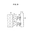
- Fig. 9 shows a second embodiment of the intake system in accordance with the invention applied to a 4-cylinder in-line engine.
- the intake system has a dual arrangement such that each intake system supplies the mixture to the combustion chambers of two cylinders.
- Each of two intake systems can have a construction same as that of the first embodiment or either one of the modifications explained hereinbefore.
Landscapes
- Engineering & Computer Science (AREA)
- Chemical & Material Sciences (AREA)
- Combustion & Propulsion (AREA)
- Mechanical Engineering (AREA)
- General Engineering & Computer Science (AREA)
- Fuel-Injection Apparatus (AREA)
Applications Claiming Priority (4)
| Application Number | Priority Date | Filing Date | Title |
|---|---|---|---|
| JP58178043A JPS6073050A (ja) | 1983-09-28 | 1983-09-28 | 内燃機関用燃料噴射装置 |
| JP178043/83 | 1983-09-28 | ||
| JP3858584A JPS60184963A (ja) | 1984-03-02 | 1984-03-02 | 燃料供給装置 |
| JP38585/84 | 1984-03-02 |
Publications (2)
| Publication Number | Publication Date |
|---|---|
| EP0140170A2 true EP0140170A2 (fr) | 1985-05-08 |
| EP0140170A3 EP0140170A3 (fr) | 1987-04-01 |
Family
ID=26377850
Family Applications (1)
| Application Number | Title | Priority Date | Filing Date |
|---|---|---|---|
| EP84111541A Withdrawn EP0140170A3 (fr) | 1983-09-28 | 1984-09-27 | Système d'admission pour moteurs à combustion interne |
Country Status (3)
| Country | Link |
|---|---|
| US (1) | US4589381A (fr) |
| EP (1) | EP0140170A3 (fr) |
| CA (1) | CA1224369A (fr) |
Cited By (9)
| Publication number | Priority date | Publication date | Assignee | Title |
|---|---|---|---|---|
| EP0219746A1 (fr) * | 1985-10-04 | 1987-04-29 | Hitachi, Ltd. | Système d'injection de carburant |
| EP0196100A3 (en) * | 1985-03-29 | 1988-04-20 | Hitachi, Ltd. | Fuel injection supply system for multi-cylinder internal combustion engine |
| EP0193773A3 (fr) * | 1985-03-06 | 1989-02-08 | Hitachi, Ltd. | Dispositif d'injection de combustible |
| WO1990006436A1 (fr) * | 1988-11-30 | 1990-06-14 | Gentec B.V. | Dispositif d'injection d'un flux de carburant liquide |
| GB2291470A (en) * | 1994-07-18 | 1996-01-24 | Outboard Marine Corp | Fuel injected two-stroke engine fuel system |
| WO2009034338A3 (fr) * | 2007-09-14 | 2009-06-04 | Scion Sprays Ltd | Moteur à combustion interne à système d'injection de carburant |
| EP2243938A1 (fr) * | 2009-04-06 | 2010-10-27 | Behr GmbH & Co. KG | Tuyau d'aspiration pour un moteur à combustion |
| WO2017133728A1 (fr) * | 2016-02-01 | 2017-08-10 | Schulz, Holger | Procédé et système d'optimisation du fonctionnement de moteurs à combustion interne munis d'une admission d'air et de carburant |
| US12085216B2 (en) | 2022-02-17 | 2024-09-10 | Arctic Cat Inc. | Multi-use fuel filler tube |
Families Citing this family (6)
| Publication number | Priority date | Publication date | Assignee | Title |
|---|---|---|---|---|
| US4805564A (en) * | 1987-09-22 | 1989-02-21 | Sharon Manufacturing Company | Engine intake manifold assembly |
| JP2760820B2 (ja) * | 1988-12-02 | 1998-06-04 | 株式会社日立製作所 | エンジンの吸気温度加減法 |
| JPH04128567A (ja) * | 1990-09-20 | 1992-04-30 | Mazda Motor Corp | エンジンの吸気装置 |
| FI93139C (fi) * | 1991-11-11 | 1995-02-27 | Waertsilae Diesel Int | Kytkentäjärjestely paineväliaineita varten isoissa dieselmoottoreissa |
| US6341597B1 (en) | 1998-11-03 | 2002-01-29 | Siemens Automotive Corporation | Fuel injection system for high vapor pressure liquid fuel |
| US6142123A (en) * | 1998-12-14 | 2000-11-07 | Cannondale Corporation | Motorcycle |
Family Cites Families (12)
| Publication number | Priority date | Publication date | Assignee | Title |
|---|---|---|---|---|
| US3024774A (en) * | 1959-02-05 | 1962-03-13 | Int Harvester Co | Tuned intake manifold |
| JPS5052428A (fr) * | 1973-09-10 | 1975-05-09 | ||
| JPS51119422A (en) * | 1975-04-10 | 1976-10-20 | Nissan Motor Co Ltd | Air suction heating system of torch ignition type engine |
| US4064696A (en) * | 1975-05-13 | 1977-12-27 | Autoipari Kutato Intezet | Live-gas conduit system for turbocharged six-cylinder engines |
| US4235375A (en) * | 1978-02-07 | 1980-11-25 | The Bendix Corporation | Fuel injection valve and single point system |
| GB2074233B (en) * | 1978-02-07 | 1983-02-02 | Bendix Corp | Fuel-handling arrangement in an ic engine fuel-injection system |
| US4212277A (en) * | 1978-03-06 | 1980-07-15 | The Bendix Corporation | Economy throttle body for hot fuel handling |
| HU175877B (en) * | 1978-07-07 | 1980-11-28 | Autoipari Kutato Intezet | Fresh gas duct system of resanator for internal combustion piston engines |
| JPS609408Y2 (ja) * | 1979-07-09 | 1985-04-03 | 日産自動車株式会社 | 内燃機関の吸気装置 |
| DE3032067A1 (de) * | 1980-08-26 | 1982-04-15 | Robert Bosch Gmbh, 7000 Stuttgart | Kraftstoffeinspritzanlage |
| DE3141154C2 (de) * | 1981-10-16 | 1993-10-21 | Bosch Gmbh Robert | Kraftstoffeinspritzanlage |
| DE3229716C2 (de) * | 1982-08-10 | 1995-01-26 | Bosch Gmbh Robert | Kraftstoffeinspritzvorrichtung |
-
1984
- 1984-09-26 US US06/654,456 patent/US4589381A/en not_active Expired - Fee Related
- 1984-09-26 CA CA000464070A patent/CA1224369A/fr not_active Expired
- 1984-09-27 EP EP84111541A patent/EP0140170A3/fr not_active Withdrawn
Cited By (10)
| Publication number | Priority date | Publication date | Assignee | Title |
|---|---|---|---|---|
| EP0193773A3 (fr) * | 1985-03-06 | 1989-02-08 | Hitachi, Ltd. | Dispositif d'injection de combustible |
| EP0196100A3 (en) * | 1985-03-29 | 1988-04-20 | Hitachi, Ltd. | Fuel injection supply system for multi-cylinder internal combustion engine |
| EP0219746A1 (fr) * | 1985-10-04 | 1987-04-29 | Hitachi, Ltd. | Système d'injection de carburant |
| WO1990006436A1 (fr) * | 1988-11-30 | 1990-06-14 | Gentec B.V. | Dispositif d'injection d'un flux de carburant liquide |
| GB2291470A (en) * | 1994-07-18 | 1996-01-24 | Outboard Marine Corp | Fuel injected two-stroke engine fuel system |
| WO2009034338A3 (fr) * | 2007-09-14 | 2009-06-04 | Scion Sprays Ltd | Moteur à combustion interne à système d'injection de carburant |
| US8479708B2 (en) | 2007-09-14 | 2013-07-09 | Robert Bosch Gmbh | Internal combustion engine with a fuel injection system |
| EP2243938A1 (fr) * | 2009-04-06 | 2010-10-27 | Behr GmbH & Co. KG | Tuyau d'aspiration pour un moteur à combustion |
| WO2017133728A1 (fr) * | 2016-02-01 | 2017-08-10 | Schulz, Holger | Procédé et système d'optimisation du fonctionnement de moteurs à combustion interne munis d'une admission d'air et de carburant |
| US12085216B2 (en) | 2022-02-17 | 2024-09-10 | Arctic Cat Inc. | Multi-use fuel filler tube |
Also Published As
| Publication number | Publication date |
|---|---|
| CA1224369A (fr) | 1987-07-21 |
| US4589381A (en) | 1986-05-20 |
| EP0140170A3 (fr) | 1987-04-01 |
Similar Documents
| Publication | Publication Date | Title |
|---|---|---|
| US4589381A (en) | Intake system for internal combustion engine | |
| EP2261496B1 (fr) | Dispositif d'alimentation en carburant | |
| KR100359702B1 (ko) | 백본형 자동이륜차의 연료분사 장치 | |
| US5735248A (en) | Fuel injection method for gas fuel engine | |
| US5012787A (en) | Fuel injection system | |
| JP2938204B2 (ja) | 自動二輪車用4サイクルエンジンの吸気装置 | |
| EP0732497B1 (fr) | Système d'injection de carburant d'un moteur à combustion interne | |
| US20020170518A1 (en) | V-type 2-cylinder engine | |
| US6932061B2 (en) | Fuel routing apparatus for a vehicular fuel tank, and fuel tank incorporating same | |
| US7584745B2 (en) | Carburetor electronic fuel injection plenum | |
| CA2204749A1 (fr) | Dispositif de reglage de carburant evapore dans un moteur a combustion interne | |
| US4516538A (en) | Intake manifold for internal combustion engines | |
| US20070144491A1 (en) | Fuel injection system for engine | |
| US3489128A (en) | Fuel supply installation for injection-type internal combustion engines | |
| JPH10196440A (ja) | 燃料噴射装置 | |
| JP3757432B2 (ja) | 燃料供給装置およびデリバリパイプ | |
| JP2797353B2 (ja) | 燃料分岐管 | |
| US12429021B2 (en) | Fuel injection throttle body assembly having a fuel distribution sleeve | |
| JPS6073050A (ja) | 内燃機関用燃料噴射装置 | |
| KR200162129Y1 (ko) | 자동차의 연료공급 파이프 | |
| KR950001985Y1 (ko) | 모세관을 설치한 공기보조분사 시스템 | |
| JPS5810154A (ja) | 燃料噴射式火花点火内燃機関のサ−ジタンク装置 | |
| US4341191A (en) | Fuel injection type carburetor | |
| JPH07293393A (ja) | 燃料噴射装置 | |
| JPS5815760A (ja) | 低速用インジエクタを有する燃料供給装置 |
Legal Events
| Date | Code | Title | Description |
|---|---|---|---|
| PUAI | Public reference made under article 153(3) epc to a published international application that has entered the european phase |
Free format text: ORIGINAL CODE: 0009012 |
|
| AK | Designated contracting states |
Designated state(s): CH DE FR GB IT LI NL SE |
|
| PUAL | Search report despatched |
Free format text: ORIGINAL CODE: 0009013 |
|
| AK | Designated contracting states |
Kind code of ref document: A3 Designated state(s): CH DE FR GB IT LI NL SE |
|
| 17P | Request for examination filed |
Effective date: 19870403 |
|
| 17Q | First examination report despatched |
Effective date: 19871005 |
|
| STAA | Information on the status of an ep patent application or granted ep patent |
Free format text: STATUS: THE APPLICATION HAS BEEN WITHDRAWN |
|
| 18W | Application withdrawn |
Withdrawal date: 19880209 |
|
| RIN1 | Information on inventor provided before grant (corrected) |
Inventor name: TAKAYAMA, TERUO |