EP0144246A2 - Herstellungsverfahren für Gitter für Farbkathodenstrahlröhren - Google Patents
Herstellungsverfahren für Gitter für Farbkathodenstrahlröhren Download PDFInfo
- Publication number
- EP0144246A2 EP0144246A2 EP84308495A EP84308495A EP0144246A2 EP 0144246 A2 EP0144246 A2 EP 0144246A2 EP 84308495 A EP84308495 A EP 84308495A EP 84308495 A EP84308495 A EP 84308495A EP 0144246 A2 EP0144246 A2 EP 0144246A2
- Authority
- EP
- European Patent Office
- Prior art keywords
- pair
- damper wire
- members
- grid elements
- fixing
- Prior art date
- Legal status (The legal status is an assumption and is not a legal conclusion. Google has not performed a legal analysis and makes no representation as to the accuracy of the status listed.)
- Granted
Links
Images

Classifications
-
- H—ELECTRICITY
- H01—ELECTRIC ELEMENTS
- H01J—ELECTRIC DISCHARGE TUBES OR DISCHARGE LAMPS
- H01J9/00—Apparatus or processes specially adapted for the manufacture, installation, removal, maintenance of electric discharge tubes, discharge lamps, or parts thereof; Recovery of material from discharge tubes or lamps
- H01J9/02—Manufacture of electrodes or electrode systems
- H01J9/14—Manufacture of electrodes or electrode systems of non-emitting electrodes
- H01J9/142—Manufacture of electrodes or electrode systems of non-emitting electrodes of shadow-masks for colour television tubes
-
- H—ELECTRICITY
- H01—ELECTRIC ELEMENTS
- H01J—ELECTRIC DISCHARGE TUBES OR DISCHARGE LAMPS
- H01J29/00—Details of cathode-ray tubes or of electron-beam tubes of the types covered by group H01J31/00
- H01J29/46—Arrangements of electrodes and associated parts for generating or controlling the ray or beam, e.g. electron-optical arrangement
- H01J29/80—Arrangements for controlling the ray or beam after passing the main deflection system, e.g. for post-acceleration or post-concentration, for colour switching
-
- H—ELECTRICITY
- H01—ELECTRIC ELEMENTS
- H01J—ELECTRIC DISCHARGE TUBES OR DISCHARGE LAMPS
- H01J2229/00—Details of cathode ray tubes or electron beam tubes
- H01J2229/07—Shadow masks
- H01J2229/0727—Aperture plate
- H01J2229/0738—Mitigating undesirable mechanical effects
- H01J2229/0744—Vibrations
-
- H—ELECTRICITY
- H01—ELECTRIC ELEMENTS
- H01J—ELECTRIC DISCHARGE TUBES OR DISCHARGE LAMPS
- H01J2229/00—Details of cathode ray tubes or electron beam tubes
- H01J2229/07—Shadow masks
- H01J2229/0727—Aperture plate
- H01J2229/075—Beam passing apertures, e.g. geometrical arrangements
- H01J2229/0755—Beam passing apertures, e.g. geometrical arrangements characterised by aperture shape
- H01J2229/0761—Uniaxial masks having parallel slit apertures, i.e. Trinitron type
Definitions
- This invention relates to methods of manufacturing electron beam selection electrodes, in particular, aperture grilles for colour cathode ray tubes, and to aperture grilles for colour cathode ray tubes.
- An aperture grille which is a kind of electron beam selection electrode, is formed by laying grid elements on a frame with predetermined spaces therebetween.
- the structure of this type of aperture grille is disclosed, for example, in U.S. patent No. 3,638,063.
- a damper wire is provided for preventing vibration, and is stretched on a surface of the grid elements laid on the frame.
- an electron beam selection electrode of a colour cathode ray tube which electrode includes a pair of arm members with a plurality of grid elements attached thereto and extended therebetween, and a pair of supporting members for said pair of arm members, the method comprising:
- a damped aperture grille comprising a pair of arm members with a plurality of grid elements attached thereto and extending therebetween generally perpendicularly thereto, a pair of transverse members connecting the ends of said arm members and maintaining said arm members in substantially fixed relation, a damper wire extending across said grid elements generally parallel to said arm members, and means tensioning and supporting said wire against said grid elements; characterised in that: said tensioning and supporting means comprises a pair of spring elements, each spring element being secured at one end to a respective end of said damper wire passing over the respective end-most gric member, and extending therefrom to a respective support arm where the other end of said spring element is attached in a spring-stressed condition applying in turn spring tension to said damper wire.
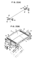
- FIG. 2B As an electron beam selection electrode according to the present invention, a so-called aperture grille including grid elements laid on a frame is used as shown in Figure 2B.
- a pair of fixing members 11 are each formed of a spring element. Portions 12 to be engaged with end portions 8 of grid elements 5 are bent to L-shape, and portions 13 to be fixed to a frame 6 are slightly bent in the reverse direction to the L-shaped portions 12. Then, the pair of fixing members 11 are arranged at positions corresponding to the length of a tungsten damper wire 1 to be stretched on the grid elements 5.
- a pair of thin film tapes 14 of stainless steel are placed on the damper wire 1 on the fixing members 11, and the damper wire 1 is seam welded to the fixing members 11 through the thin film tapes 14 over a distance of 5 to 6 mm, by means of a pair of roller electrodes 15 driven in a direction perpendicular to the damper wire 1 as shown in Figure 2(A).
- the thickness of the thin film tapes 14 is preferably about 70 microns, for example. After seam welding, unnecessary portions of the thin film tapes 14 are trimmed off.
- both the fixing members 11 with the damper wire 1 secured thereto are placed on the surface of the grid elements 5 of the aperture grille 7, and the L-shaped portions 12 of the fixing members 11 are engaged with the end portions 8 of the grid elements 5.
- the portions 13 of the fixing members 11 are simultaneously fixed to the frame 6 by spot welding with a spot welding machine 16.
- the engagement of the L-shaped portions 12 of the fixing members 11 with the end portions 8 of the grid elements 5 is released.
- the L-shaped portions 12 of the fixing members 11 then move outwardly away from the end portions 8 in a direction parallel to a surface of the grid elements 5. Accordingly the damper wire 1 is easily and securely stretched on the aperture grille.
- the damper wire 1 is single in the preferred embodiment, two or more damper wires may be provided if required.
- the damper wire 1 is welded through the thin film tapes 14 to the fixing members 11, there is no possibility of faulty embedding of the damper wire 1 into the fixing members 11 as in the prior art. Moreover, as the above-mentioned welding is carried out with use of roller type electrodes 15, there is no possibility that a particular portion of the electrodes 15 is significantly deformed. Accordingly, it is possible easily and surely to carry out stretching of the damper wire 1 between the two fixing members 11, and fixing of both the fixing members 11 to the frame 6. Further, as the L-shaped portions 12 are engaged with the end portions 8 of the grid elements 5, the fixing members 11 may be accurately positioned with respect to a direction (Z direction) perpendicular to a surface of the grid elements 5. Accordingly, it is possible to eliminate displacement of the grid elements 5 due to the damper wire 1 upon installation of the damper wire 1, thereby eliminating mislanding due to stretching of the damper wire 1.
Landscapes
- Engineering & Computer Science (AREA)
- Manufacturing & Machinery (AREA)
- Electrodes For Cathode-Ray Tubes (AREA)
Applications Claiming Priority (2)
| Application Number | Priority Date | Filing Date | Title |
|---|---|---|---|
| JP58232064A JPS60127639A (ja) | 1983-12-08 | 1983-12-08 | カラ−陰極線管の製法 |
| JP232064/83 | 1983-12-08 |
Publications (3)
| Publication Number | Publication Date |
|---|---|
| EP0144246A2 true EP0144246A2 (de) | 1985-06-12 |
| EP0144246A3 EP0144246A3 (en) | 1985-07-10 |
| EP0144246B1 EP0144246B1 (de) | 1989-02-08 |
Family
ID=16933411
Family Applications (1)
| Application Number | Title | Priority Date | Filing Date |
|---|---|---|---|
| EP84308495A Expired EP0144246B1 (de) | 1983-12-08 | 1984-12-06 | Herstellungsverfahren für Gitter für Farbkathodenstrahlröhren |
Country Status (4)
| Country | Link |
|---|---|
| US (1) | US4682965A (de) |
| EP (1) | EP0144246B1 (de) |
| JP (1) | JPS60127639A (de) |
| DE (1) | DE3476720D1 (de) |
Cited By (1)
| Publication number | Priority date | Publication date | Assignee | Title |
|---|---|---|---|---|
| GB2260856A (en) * | 1991-10-24 | 1993-04-28 | Sony Corp | Colour selecting structure for a cathode-ray tube |
Families Citing this family (5)
| Publication number | Priority date | Publication date | Assignee | Title |
|---|---|---|---|---|
| JPH07254359A (ja) * | 1994-03-16 | 1995-10-03 | Sony Corp | ダンパーワイヤ張架方法とダンパーワイヤ張架装置 |
| JPH09251837A (ja) * | 1996-03-15 | 1997-09-22 | Sony Corp | 陰極線管の製造方法 |
| JP3089627B1 (ja) * | 1999-06-15 | 2000-09-18 | ソニー株式会社 | 色選別体およびその振動防止方法並びに陰極線菅 |
| US6879093B2 (en) * | 2000-12-22 | 2005-04-12 | Thomson Licensing S.A. | Damper wire spring for a cathode ray tube |
| US6566799B1 (en) * | 2001-11-15 | 2003-05-20 | Thomson Licensing, S.A. | Cathode ray tubes having damper wire support springs |
Family Cites Families (4)
| Publication number | Priority date | Publication date | Assignee | Title |
|---|---|---|---|---|
| US2279451A (en) * | 1939-11-09 | 1942-04-14 | Du Pont | Electric blasting initiator |
| SE348317B (de) * | 1968-01-11 | 1972-08-28 | Sony Corp Kk | |
| FR2106913A5 (fr) * | 1970-09-29 | 1972-05-05 | France-Couleur | Procede et installation pour monter des fils paralleles et tendus entre deux cotes opposes d'un cadre |
| NL169806C (nl) * | 1972-02-07 | 1982-08-16 | Hoechst Ag | Draadvormige sproei-elektrode voor een corona-ontladingsinrichting. |
-
1983
- 1983-12-08 JP JP58232064A patent/JPS60127639A/ja active Granted
-
1984
- 1984-12-04 US US06/678,038 patent/US4682965A/en not_active Expired - Lifetime
- 1984-12-06 EP EP84308495A patent/EP0144246B1/de not_active Expired
- 1984-12-06 DE DE8484308495T patent/DE3476720D1/de not_active Expired
Cited By (4)
| Publication number | Priority date | Publication date | Assignee | Title |
|---|---|---|---|---|
| GB2260856A (en) * | 1991-10-24 | 1993-04-28 | Sony Corp | Colour selecting structure for a cathode-ray tube |
| US5382871A (en) * | 1991-10-24 | 1995-01-17 | Sony Corporation | Color selecting structure for a cathode-ray tube |
| GB2260856B (en) * | 1991-10-24 | 1995-09-13 | Sony Corp | Colour selecting structure for a cathode-ray tube |
| DE4235925C2 (de) * | 1991-10-24 | 2003-05-28 | Sony Corp | Farbauswahlmaske für eine Katodenstrahlröhre |
Also Published As
| Publication number | Publication date |
|---|---|
| JPS60127639A (ja) | 1985-07-08 |
| DE3476720D1 (en) | 1989-03-16 |
| US4682965A (en) | 1987-07-28 |
| EP0144246B1 (de) | 1989-02-08 |
| JPH0468729B2 (de) | 1992-11-04 |
| EP0144246A3 (en) | 1985-07-10 |
Similar Documents
| Publication | Publication Date | Title |
|---|---|---|
| EP0198475B1 (de) | Farbwahlelektrode für eine Kathodenstrahlröhre | |
| KR20030075221A (ko) | 텐션 마스크 프레임 조립체의 제조방법 및 그 제조방치 | |
| KR900003902B1 (ko) | 칼라 표시관 | |
| EP0144246A2 (de) | Herstellungsverfahren für Gitter für Farbkathodenstrahlröhren | |
| US5204583A (en) | Filament supporter for use in vacuum fluorescent display tubes and method for filament installation | |
| US6188169B1 (en) | Aperture grill supporting frame and manufacturing method thereof | |
| JP2985797B2 (ja) | カラー陰極線管、陰極線管の色選別機構及び色選別機構用フレーム | |
| EP1116257B1 (de) | Schlitzmaskenstruktur für kathodenstrahlröhre | |
| JP3422098B2 (ja) | 色選別装置及びカラー陰極線管 | |
| US6604974B2 (en) | Method and apparatus for applying crosswires to a tension focus mask | |
| KR100206282B1 (ko) | 음극선관의 텐션새도우마스크와 프레임로딩용 위치설정핀 설치방법 | |
| CA1169479A (en) | Method of manufacturing a colour television display tube and colour television display tube manufactured according to the method | |
| JPS6062039A (ja) | 補強形ブラウン管 | |
| US5951351A (en) | Method for manufacturing an electron gun | |
| JP2000067748A (ja) | カラー陰極線管の製造方法 | |
| JP2000011912A (ja) | 陰極線管の色選別機構 | |
| JPH097505A (ja) | カラー陰極線管の色選別電極装置の製造方法 | |
| JPH10188794A (ja) | フラットアパーチャーグリル | |
| JPH10302662A (ja) | 陰極線管の色選別機構 | |
| JPS5816738B2 (ja) | ブラウン管電子銃のヒ−タ組立方法 | |
| JPH04289631A (ja) | 陰極線管の色選別電極のダンパ線張設方法 | |
| JPH09147759A (ja) | カラー陰極線管用色選別電極構体、カラー陰極線管用色選別電極構体の組立方法及びカラー陰極線管用色選別電極構体の組立装置 | |
| JPH06103913A (ja) | カラーブラウン管の内部磁気シールド取付構造 | |
| JPH04289635A (ja) | カラーブラウン管色選別電極用フレーム | |
| JPH08335441A (ja) | 色選択電極およびダンパー線の固定方法 |
Legal Events
| Date | Code | Title | Description |
|---|---|---|---|
| PUAI | Public reference made under article 153(3) epc to a published international application that has entered the european phase |
Free format text: ORIGINAL CODE: 0009012 |
|
| PUAL | Search report despatched |
Free format text: ORIGINAL CODE: 0009013 |
|
| AK | Designated contracting states |
Designated state(s): DE FR GB |
|
| AK | Designated contracting states |
Designated state(s): DE FR GB |
|
| 17P | Request for examination filed |
Effective date: 19851122 |
|
| 17Q | First examination report despatched |
Effective date: 19870615 |
|
| GRAA | (expected) grant |
Free format text: ORIGINAL CODE: 0009210 |
|
| AK | Designated contracting states |
Kind code of ref document: B1 Designated state(s): DE FR GB |
|
| REF | Corresponds to: |
Ref document number: 3476720 Country of ref document: DE Date of ref document: 19890316 |
|
| ET | Fr: translation filed | ||
| PLBE | No opposition filed within time limit |
Free format text: ORIGINAL CODE: 0009261 |
|
| STAA | Information on the status of an ep patent application or granted ep patent |
Free format text: STATUS: NO OPPOSITION FILED WITHIN TIME LIMIT |
|
| 26N | No opposition filed | ||
| REG | Reference to a national code |
Ref country code: GB Ref legal event code: IF02 |
|
| PGFP | Annual fee paid to national office [announced via postgrant information from national office to epo] |
Ref country code: GB Payment date: 20031203 Year of fee payment: 20 |
|
| PGFP | Annual fee paid to national office [announced via postgrant information from national office to epo] |
Ref country code: FR Payment date: 20031210 Year of fee payment: 20 |
|
| PGFP | Annual fee paid to national office [announced via postgrant information from national office to epo] |
Ref country code: DE Payment date: 20031218 Year of fee payment: 20 |
|
| PG25 | Lapsed in a contracting state [announced via postgrant information from national office to epo] |
Ref country code: GB Free format text: LAPSE BECAUSE OF EXPIRATION OF PROTECTION Effective date: 20041205 |
|
| REG | Reference to a national code |
Ref country code: GB Ref legal event code: PE20 |