EP0145935A1 - Verfahren und Vorrichtung zur Ermittlung der Position und Geschwindigkeit eines bewegten Körpers - Google Patents
Verfahren und Vorrichtung zur Ermittlung der Position und Geschwindigkeit eines bewegten Körpers Download PDFInfo
- Publication number
- EP0145935A1 EP0145935A1 EP84113427A EP84113427A EP0145935A1 EP 0145935 A1 EP0145935 A1 EP 0145935A1 EP 84113427 A EP84113427 A EP 84113427A EP 84113427 A EP84113427 A EP 84113427A EP 0145935 A1 EP0145935 A1 EP 0145935A1
- Authority
- EP
- European Patent Office
- Prior art keywords
- velocity
- encoder
- pulse
- width
- detecting
- Prior art date
- Legal status (The legal status is an assumption and is not a legal conclusion. Google has not performed a legal analysis and makes no representation as to the accuracy of the status listed.)
- Granted
Links
- 238000000034 method Methods 0.000 title claims abstract description 35
- 238000005070 sampling Methods 0.000 claims abstract description 19
- 238000001514 detection method Methods 0.000 description 26
- 238000010586 diagram Methods 0.000 description 6
- NCGICGYLBXGBGN-UHFFFAOYSA-N 3-morpholin-4-yl-1-oxa-3-azonia-2-azanidacyclopent-3-en-5-imine;hydrochloride Chemical compound Cl.[N-]1OC(=N)C=[N+]1N1CCOCC1 NCGICGYLBXGBGN-UHFFFAOYSA-N 0.000 description 2
- 238000010276 construction Methods 0.000 description 2
- 230000000694 effects Effects 0.000 description 2
- 238000007493 shaping process Methods 0.000 description 2
- 230000001360 synchronised effect Effects 0.000 description 2
- 230000003247 decreasing effect Effects 0.000 description 1
- 230000000630 rising effect Effects 0.000 description 1
- 239000004065 semiconductor Substances 0.000 description 1
- 230000004304 visual acuity Effects 0.000 description 1
Images


Classifications
-
- G—PHYSICS
- G01—MEASURING; TESTING
- G01P—MEASURING LINEAR OR ANGULAR SPEED, ACCELERATION, DECELERATION, OR SHOCK; INDICATING PRESENCE, ABSENCE, OR DIRECTION, OF MOVEMENT
- G01P3/00—Measuring linear or angular speed; Measuring differences of linear or angular speeds
- G01P3/42—Devices characterised by the use of electric or magnetic means
- G01P3/44—Devices characterised by the use of electric or magnetic means for measuring angular speed
- G01P3/48—Devices characterised by the use of electric or magnetic means for measuring angular speed by measuring frequency of generated current or voltage
- G01P3/481—Devices characterised by the use of electric or magnetic means for measuring angular speed by measuring frequency of generated current or voltage of pulse signals
- G01P3/489—Digital circuits therefor
-
- G—PHYSICS
- G01—MEASURING; TESTING
- G01D—MEASURING NOT SPECIALLY ADAPTED FOR A SPECIFIC VARIABLE; ARRANGEMENTS FOR MEASURING TWO OR MORE VARIABLES NOT COVERED IN A SINGLE OTHER SUBCLASS; TARIFF METERING APPARATUS; MEASURING OR TESTING NOT OTHERWISE PROVIDED FOR
- G01D5/00—Mechanical means for transferring the output of a sensing member; Means for converting the output of a sensing member to another variable where the form or nature of the sensing member does not constrain the means for converting; Transducers not specially adapted for a specific variable
- G01D5/12—Mechanical means for transferring the output of a sensing member; Means for converting the output of a sensing member to another variable where the form or nature of the sensing member does not constrain the means for converting; Transducers not specially adapted for a specific variable using electric or magnetic means
- G01D5/244—Mechanical means for transferring the output of a sensing member; Means for converting the output of a sensing member to another variable where the form or nature of the sensing member does not constrain the means for converting; Transducers not specially adapted for a specific variable using electric or magnetic means influencing characteristics of pulses or pulse trains; generating pulses or pulse trains
- G01D5/246—Mechanical means for transferring the output of a sensing member; Means for converting the output of a sensing member to another variable where the form or nature of the sensing member does not constrain the means for converting; Transducers not specially adapted for a specific variable using electric or magnetic means influencing characteristics of pulses or pulse trains; generating pulses or pulse trains by varying the duration of individual pulses
-
- G—PHYSICS
- G01—MEASURING; TESTING
- G01P—MEASURING LINEAR OR ANGULAR SPEED, ACCELERATION, DECELERATION, OR SHOCK; INDICATING PRESENCE, ABSENCE, OR DIRECTION, OF MOVEMENT
- G01P3/00—Measuring linear or angular speed; Measuring differences of linear or angular speeds
- G01P3/42—Devices characterised by the use of electric or magnetic means
- G01P3/44—Devices characterised by the use of electric or magnetic means for measuring angular speed
-
- Y—GENERAL TAGGING OF NEW TECHNOLOGICAL DEVELOPMENTS; GENERAL TAGGING OF CROSS-SECTIONAL TECHNOLOGIES SPANNING OVER SEVERAL SECTIONS OF THE IPC; TECHNICAL SUBJECTS COVERED BY FORMER USPC CROSS-REFERENCE ART COLLECTIONS [XRACs] AND DIGESTS
- Y10—TECHNICAL SUBJECTS COVERED BY FORMER USPC
- Y10S—TECHNICAL SUBJECTS COVERED BY FORMER USPC CROSS-REFERENCE ART COLLECTIONS [XRACs] AND DIGESTS
- Y10S388/00—Electricity: motor control systems
- Y10S388/90—Specific system operational feature
- Y10S388/901—Sample and hold
-
- Y—GENERAL TAGGING OF NEW TECHNOLOGICAL DEVELOPMENTS; GENERAL TAGGING OF CROSS-SECTIONAL TECHNOLOGIES SPANNING OVER SEVERAL SECTIONS OF THE IPC; TECHNICAL SUBJECTS COVERED BY FORMER USPC CROSS-REFERENCE ART COLLECTIONS [XRACs] AND DIGESTS
- Y10—TECHNICAL SUBJECTS COVERED BY FORMER USPC
- Y10S—TECHNICAL SUBJECTS COVERED BY FORMER USPC CROSS-REFERENCE ART COLLECTIONS [XRACs] AND DIGESTS
- Y10S388/00—Electricity: motor control systems
- Y10S388/907—Specific control circuit element or device
- Y10S388/912—Pulse or frequency counter
-
- Y—GENERAL TAGGING OF NEW TECHNOLOGICAL DEVELOPMENTS; GENERAL TAGGING OF CROSS-SECTIONAL TECHNOLOGIES SPANNING OVER SEVERAL SECTIONS OF THE IPC; TECHNICAL SUBJECTS COVERED BY FORMER USPC CROSS-REFERENCE ART COLLECTIONS [XRACs] AND DIGESTS
- Y10—TECHNICAL SUBJECTS COVERED BY FORMER USPC
- Y10S—TECHNICAL SUBJECTS COVERED BY FORMER USPC CROSS-REFERENCE ART COLLECTIONS [XRACs] AND DIGESTS
- Y10S388/00—Electricity: motor control systems
- Y10S388/907—Specific control circuit element or device
- Y10S388/915—Sawtooth or ramp waveform generator
Definitions
- This invention relates to a method and an apparatus for detecting the position and the velocity, in particular to a method and an apparatus suitable for detecting low speed rotation with high precision by pulse-width modulating original signals coming from an encoder.
- FIG. 1 A method for controlling digitally the velocity of a moving or rotating body such as an electric motor is explained by referring to the block diagram representing a prior art velocity control apparatus shown in Fig. 1.
- reference numeral 1 denotes a microcomputer
- 2 a velocity command section receiving orders from a host system
- 3 a gating circuit for supplying electric current command calculated by the microcomputer 1 to an electric power converter 4
- 5 a control motor
- Reference numeral 6 represents a pulse generator, which generates n pulses per turn and generates an output pulse PLG and which is connected directly to the control motor
- 7 denotes a velocity detection circuit.
- a signal processing circuit is necessary in order to obtain a velocity detection value N f as a digital value from the microcomputer 1 by counting pulses coming from the pulse generator 6.
- the number of pulses P N relating to the counted value becomes smaller and the resolving power is lowered with decreasing velocity.
- FIG. 2 is a block diagram representing a velocity detection circuit used in the velocity detection method previously developed by the inventors of the present invention by using encoder pulses
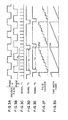
- Figs. 3A - 3G are time charts for the velocity detection
- Figs. 4A - 4G are time charts for the low velocity detection.
- the microcomputer is made up of a CPU 101, a ROM 102 and a RAM 103, as indicated in Fig. 2, and effects control for velocity detection and operations.
- the velocity can be obtained by using the number of pulses P N during a certain time interval and its time width T d according to the following equation (1) in which K1 is a constant, which is determined by the number of encoder pulses per turn.
- the encoder is, in general, mounted on the shaft of a servo-motor and generates 2 encoder pulse signals having different phases, i.e. phase A and phase B, which are different by 90° from each other, as indicated in Figs. 3A and 3B.
- Reference numeral 108 represents an encoder pulse shaping circuit, which detects rising and falling edges of the encoder pulse signals having different phases and generates signals T 1 indicated in Fig. 3.
- reference numeral 104 represents a sampling timer connected to a data bus 110 of the microcomputer, which timer generates signals T 2' indicated in Fig. 3D having a width corresponding to the sampling time interval T s for detecting the velocity.
- Reference numeral 105 represents a pulse counter connected to the data bus 110, which counter counts the number of encoder pulse signals T 1 during the sampling time interval T s , as indicated in Fig. 3F.
- Reference numeral 107 is a synchronizing circuit, which latches by using the encoder pulse signal T 1 the signals T 2 to be used for sampling. Output of this synchronizing circuit 107 is signals T 3 indicated in Fig. 3E.
- Reference numeral 106 represents a time width timer connected to the data bus 110 of the microcomputer as in the case of the sampling timer 104 and the pulse counter 105 and it measures the time width T d of the output signals T 3 of the synchronizing circuit 107 as shown in Fig. 3G.
- Data about the time width T d thus measured are taken through the data bus 110 in the microcomputer.
- the microcomputer carries out operations according to the equation (1) mentioned above, using the data about the number of encoder pulses P N and those about the time width T d , which are taken therein, as indicated above, in order to detect the velocity V F .
- Figs. 4A - 4G are time charts for low speed rotation.
- the sampling time T S cannot be synchronized with the encoder pulse signal T 1 (domain )
- the time width T d is excessively long, although it is synchronized (domain A).
- an object of this invention is to provide a method for detecting the position and the velocity of a displacing body, which works stably for low velocity detection and permits to detect it within a sampling time interval and apparatus for detecting the position and the velocity, which can be used for implementing the method.
- a method for detecting the position and the velocity by using an encoder mounted directly on the displacing body comprises the steps of pulse-width modulating original signals of the encoder by using a sampling carrier wave and measuring the width of the pulses generated by pulse-width modulating the original signal to detect the position.
- an apparatus for detecting the position and the velocity of a moving body by using an encoder mounted directly on the moving body comprises a carrier wave generation circuit for generating a carrier wave, a pulse width modulation circuit which pulse-width modulates the original signals coming from the encoder by using the carrier wave, a pulse width timer which measures the width of the pulses generated by pulse-width modulating the original signals, and a microcomputer connected to the pulse width timer.
- the device is constructed as follows.
- an encoder generates original signals varying sinusoidally and encoder pulses are produced by shaping these encoder original signals.
- these encoder original signals varying sinusoidally are utilized for the velocity detection.
- these encoder original signals are modulated by using a sampling carrier wave according to pulse width modulation techniques.
- the time-length of the width of the pulses thus modulated is measured in order to detect the position of the encoder original signals and the velocity of the moving body is detected on the basis of the variations of the position.
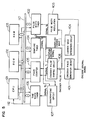
- Fig. 5 is a block diagram showing the construction of an apparatus for detecting the position and the velocity for implementing the method for detecting the position and the velocity according to an embodiment of the invention
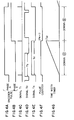
- Fig. 6 is a time chart for low speed detection, when the apparatus shown in Fig. 5 is used
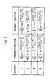
- Fig. 7 is a scheme showing the position for every quadrant used for calculation of phase data
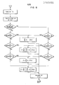
- Fig. 8 is a flow chart for calculating the position according the method of the present invention.
- reference numeral 401 denotes an encoder pulse generation circuit, which generates encoder pulses from encoder original signals.
- Reference numeral 404 denotes a carrier wave generation circuit which generates carrier wave pulses having a width corresponding to a sampling time T S and forms a sawtooth shaped sampling carrier wave
- 403 is a pulse width modulation circuit which compares the sampling carrier wave with phase A encoder original signals and generates pulse-width modulated signals S 1 .
- Reference numeral 402 is a pulse width timer connected to the data bus 110 of a microcomputer, which timer measures the pulse width T E representing the width in time of the pulse width modulated signals S 1 which are output signals of the pulse width modulation circuit 403 and measured data about the pulse width T E thus obtained are taken in the CPU 101.
- the velocity V F can be calculated from the following equation (3) by using ⁇ (k) and e(k-1) obtained as above, where, ⁇ (k-1) is position data obtained the last time.
- Fig. 8 is a flow chart for calculating the position data ⁇ (k) according to Fig. 7.
- A(k) in the equation (2) is abbreviated to A.
- the pulse width timer 402 requests interruption to the CPU 101 for each period of the carrier wave and upon reception of the interruption request the CPU 101 carries out calculations according to the flow chart shown in Fig. 8.
- the CPU 101 fetches the data about the pulse width T E , calculates A(k) according to the equation (2), determines the direction of the rotation, forward or reverse, and finally calculates the position data ⁇ (k) in each of the quadrants.
- sin -1 can be obtained by calculation, but taking the operation speed of the CPU 101 used into account, it is also possible to use a table of values of sin -1 to obtain the values of sin- l .
- the velocity can be calculated according to the equation (3) in the main routine.
- the velocity can be detected for every sampling with a high precision.
- this invention a wide range velocity detection can be carried out for each sampling.
- this invention has an advantage that speed control response is increased for low speed rotation. Furthermore, detection of standstill of the motor (zero speed detection), which was impossible by the method previously developed by the inventors, is possible by this method. Thus, this invention contributes greatly to improvement of the controllability. Moreover, in the position control for a servo-motor the position detection can be effected for fine positions, and thus this invention has an eminent effect that precision of the position control is increased.
- this invention can be easily applied also to a linearly moving body, such as a linear motor, an XY table, a linear scale, etc.
Landscapes
- Physics & Mathematics (AREA)
- General Physics & Mathematics (AREA)
- Transmission And Conversion Of Sensor Element Output (AREA)
- Control Of Position Or Direction (AREA)
- Control Of Electric Motors In General (AREA)
Applications Claiming Priority (2)
| Application Number | Priority Date | Filing Date | Title |
|---|---|---|---|
| JP58208221A JPH0627653B2 (ja) | 1983-11-08 | 1983-11-08 | 位置、速度検出方法及び装置 |
| JP208221/83 | 1983-11-08 |
Publications (2)
| Publication Number | Publication Date |
|---|---|
| EP0145935A1 true EP0145935A1 (de) | 1985-06-26 |
| EP0145935B1 EP0145935B1 (de) | 1988-02-24 |
Family
ID=16552672
Family Applications (1)
| Application Number | Title | Priority Date | Filing Date |
|---|---|---|---|
| EP84113427A Expired EP0145935B1 (de) | 1983-11-08 | 1984-11-07 | Verfahren und Vorrichtung zur Ermittlung der Position und Geschwindigkeit eines bewegten Körpers |
Country Status (4)
| Country | Link |
|---|---|
| US (1) | US4628314A (de) |
| EP (1) | EP0145935B1 (de) |
| JP (1) | JPH0627653B2 (de) |
| DE (1) | DE3469458D1 (de) |
Cited By (11)
| Publication number | Priority date | Publication date | Assignee | Title |
|---|---|---|---|---|
| DE3618891A1 (de) * | 1986-06-05 | 1987-12-10 | Siemens Ag | Verfahren zur ermittlung von lageistwerten einer sich drehenden vorrichtung und schaltungsanordnung zur durchfuehrung des verfahrens |
| FR2601764A1 (fr) * | 1986-07-21 | 1988-01-22 | Eimco Secoma | Capteur de position du piston pour perforatrice, et dispositif de controle comportant application de ce capteur |
| EP0274841A3 (de) * | 1986-12-09 | 1990-04-11 | Renishaw plc | Verarbeitung von verschiedenen Signalen |
| EP0358989A3 (en) * | 1988-08-24 | 1990-04-11 | Hitachi, Ltd. | Position or speed sensing apparatus and method |
| WO1991005298A1 (de) * | 1989-09-27 | 1991-04-18 | Robert Bosch Gmbh | Verfahren und vorrichtung zur nachbildung der geschwindigkeit bei inkrementalen messsystemen |
| EP0162268B1 (de) * | 1984-04-12 | 1991-07-24 | Hitachi, Ltd. | Verfahren und Vorrichtung zur Stellungs-/Geschwindigkeitsermittlung |
| FR2679338A1 (fr) * | 1991-07-20 | 1993-01-22 | Westland Aerostructures Ltd | Capteur de vitesse de roue de vehicule, procede de production d'impulsions de marquage dans un dispositif de mesure et procede de mesure de la vitesse de rotation d'un objet en rotation. |
| DE3891423C1 (de) * | 1988-10-20 | 1997-01-23 | Kayaba Industry Co Ltd | Verfahren zum Verarbeiten von Positionssignalen |
| EP0814247A3 (de) * | 1996-06-18 | 1999-10-13 | Robert Bosch Gmbh | Drehzahlsignalausgabe |
| WO2007136854A3 (en) * | 2006-05-19 | 2008-04-03 | Watlow Electric Mfg | Sensor adaptors and methods |
| US7496469B2 (en) | 2006-05-19 | 2009-02-24 | Watlow Electric Manufacturing Company | Temperature sensor adaptors and methods |
Families Citing this family (15)
| Publication number | Priority date | Publication date | Assignee | Title |
|---|---|---|---|---|
| JPS63263418A (ja) * | 1987-04-22 | 1988-10-31 | Kayaba Ind Co Ltd | 位置検出信号処理方式 |
| JP2637158B2 (ja) * | 1988-04-21 | 1997-08-06 | カヤバ工業株式会社 | 位置検出信号の処理方式 |
| JPH0239208A (ja) * | 1988-07-28 | 1990-02-08 | Fanuc Ltd | 原点復帰方法 |
| US4939675A (en) * | 1988-12-22 | 1990-07-03 | Chrysler Corporation | Digital system for controlling mechanical instrument gauges |
| US4879754A (en) * | 1989-03-14 | 1989-11-07 | Matsushita Electric Industrial Co., Ltd. | Speed controller |
| US5160886A (en) * | 1991-02-14 | 1992-11-03 | Carlen Controls, Inc. | Permanent magnet resolver for producing a resolver-to-digital converter compatible output |
| JP2833401B2 (ja) * | 1993-03-23 | 1998-12-09 | 三菱電機株式会社 | 駆動制御装置 |
| US5517099A (en) * | 1993-06-15 | 1996-05-14 | International Modern Technologies, Inc. | Method and apparatus for robust integral-pulse control of a servodrive of unknown dynamics |
| US5630008A (en) * | 1993-12-28 | 1997-05-13 | Mitsumi Electric Co., Ltd. | Control circuit for driving motor with reduced power consumption and disk unit having the control circuit |
| JP3700325B2 (ja) * | 1997-05-21 | 2005-09-28 | 松下電器産業株式会社 | 駆動源制御方法 |
| DE19937155A1 (de) * | 1999-08-06 | 2001-03-15 | Bosch Gmbh Robert | System zur Erzeugung eines Signals zur Überlagerung von Informationen |
| US7722362B2 (en) | 2006-06-22 | 2010-05-25 | Watlow Electric Manufacturing Company | Sensor adaptor circuit housing incapsulating connection of an input connector with a wire |
| CN101893457B (zh) * | 2010-06-22 | 2011-07-27 | 南京航空航天大学 | 连续运动高精度全参数检测方法 |
| US8932143B2 (en) | 2012-10-12 | 2015-01-13 | Mattel, Inc. | Control system for a child swing |
| DE102014216295A1 (de) | 2014-08-15 | 2016-02-18 | Continental Teves Ag & Co. Ohg | Auflösungserhöhung im Drehzahlsignal zwischen Drehzahlpulsen |
Citations (8)
| Publication number | Priority date | Publication date | Assignee | Title |
|---|---|---|---|---|
| DE1925100A1 (de) * | 1968-05-17 | 1969-11-27 | Sony Corp | Vorrichtung zur Bewegungsmessung |
| FR2131719A5 (de) * | 1971-03-30 | 1972-11-10 | Fiat Spa | |
| US3714538A (en) * | 1971-09-13 | 1973-01-30 | Cincinnati Milacron Inc | Velocimeter |
| US4019145A (en) * | 1976-06-24 | 1977-04-19 | Rockwell International Corporation | Synchro rate generator |
| US4228396A (en) * | 1978-05-26 | 1980-10-14 | Dataproducts Corporation | Electronic tachometer and combined brushless motor commutation and tachometer system |
| EP0059433A1 (de) * | 1981-02-28 | 1982-09-08 | Hitachi, Ltd. | Vorrichtung zur Geschwindigkeitsermittlung |
| EP0059244A2 (de) * | 1981-03-02 | 1982-09-08 | Siemens Aktiengesellschaft | Vorrichtung zur Drehzahlerfassung |
| DE3123002A1 (de) * | 1981-06-10 | 1983-01-05 | Siemens AG, 1000 Berlin und 8000 München | Verfahren und einrichtung zur drehzahlmessung einer mit einem rotierenden impulsgeber gekuppelten welle |
Family Cites Families (11)
| Publication number | Priority date | Publication date | Assignee | Title |
|---|---|---|---|---|
| US3616692A (en) * | 1969-09-08 | 1971-11-02 | Leach Corp | Data acquisition system |
| US3670324A (en) * | 1970-03-27 | 1972-06-13 | John B Trevor | Analog-digital shaft position encoder |
| JPS5129416A (en) * | 1974-09-03 | 1976-03-12 | Mitsubishi Gas Chemical Co | Hidorajin karubonirukagobutsuno seizohoho |
| US4038588A (en) * | 1976-02-03 | 1977-07-26 | The United States Of America As Represented By The Secretary Of The Air Force | Precision amplitude control system for a high q torsion pendulum |
| SU702478A1 (ru) * | 1977-09-30 | 1979-12-05 | Всесоюзный Научно-Исследовательский Кинофотоинститут (Никфи) | Частотно-регулируемый электропривод с широтно-импульсной модул цией |
| JPS5541581A (en) * | 1978-09-20 | 1980-03-24 | Canon Inc | Servo control system |
| US4288730A (en) * | 1978-09-25 | 1981-09-08 | General Motors Corporation | Proportional and integral solenoid armature positioning control system |
| JPS618378Y2 (de) * | 1980-01-21 | 1986-03-14 | ||
| US4323829A (en) * | 1980-07-28 | 1982-04-06 | Barry M. Fish | Capacitive sensor control system |
| US4481468A (en) * | 1981-05-14 | 1984-11-06 | Toshiba Kikai Kabushiki Kaisha | Velocity detecting apparatus having a two-phase resolver |
| US4468617A (en) * | 1982-02-11 | 1984-08-28 | General Electric Company | Velocity sensor and method of producing a velocity signal |
-
1983
- 1983-11-08 JP JP58208221A patent/JPH0627653B2/ja not_active Expired - Lifetime
-
1984
- 1984-11-07 EP EP84113427A patent/EP0145935B1/de not_active Expired
- 1984-11-07 US US06/668,893 patent/US4628314A/en not_active Expired - Fee Related
- 1984-11-07 DE DE8484113427T patent/DE3469458D1/de not_active Expired
Patent Citations (8)
| Publication number | Priority date | Publication date | Assignee | Title |
|---|---|---|---|---|
| DE1925100A1 (de) * | 1968-05-17 | 1969-11-27 | Sony Corp | Vorrichtung zur Bewegungsmessung |
| FR2131719A5 (de) * | 1971-03-30 | 1972-11-10 | Fiat Spa | |
| US3714538A (en) * | 1971-09-13 | 1973-01-30 | Cincinnati Milacron Inc | Velocimeter |
| US4019145A (en) * | 1976-06-24 | 1977-04-19 | Rockwell International Corporation | Synchro rate generator |
| US4228396A (en) * | 1978-05-26 | 1980-10-14 | Dataproducts Corporation | Electronic tachometer and combined brushless motor commutation and tachometer system |
| EP0059433A1 (de) * | 1981-02-28 | 1982-09-08 | Hitachi, Ltd. | Vorrichtung zur Geschwindigkeitsermittlung |
| EP0059244A2 (de) * | 1981-03-02 | 1982-09-08 | Siemens Aktiengesellschaft | Vorrichtung zur Drehzahlerfassung |
| DE3123002A1 (de) * | 1981-06-10 | 1983-01-05 | Siemens AG, 1000 Berlin und 8000 München | Verfahren und einrichtung zur drehzahlmessung einer mit einem rotierenden impulsgeber gekuppelten welle |
Cited By (13)
| Publication number | Priority date | Publication date | Assignee | Title |
|---|---|---|---|---|
| EP0162268B1 (de) * | 1984-04-12 | 1991-07-24 | Hitachi, Ltd. | Verfahren und Vorrichtung zur Stellungs-/Geschwindigkeitsermittlung |
| DE3618891A1 (de) * | 1986-06-05 | 1987-12-10 | Siemens Ag | Verfahren zur ermittlung von lageistwerten einer sich drehenden vorrichtung und schaltungsanordnung zur durchfuehrung des verfahrens |
| FR2601764A1 (fr) * | 1986-07-21 | 1988-01-22 | Eimco Secoma | Capteur de position du piston pour perforatrice, et dispositif de controle comportant application de ce capteur |
| EP0274841A3 (de) * | 1986-12-09 | 1990-04-11 | Renishaw plc | Verarbeitung von verschiedenen Signalen |
| EP0358989A3 (en) * | 1988-08-24 | 1990-04-11 | Hitachi, Ltd. | Position or speed sensing apparatus and method |
| US5019773A (en) * | 1988-08-24 | 1991-05-28 | Hitachi, Ltd. | Method and apparatus for detecting positions and/or speed of a moving body using two phase signals |
| DE3891423C1 (de) * | 1988-10-20 | 1997-01-23 | Kayaba Industry Co Ltd | Verfahren zum Verarbeiten von Positionssignalen |
| WO1991005298A1 (de) * | 1989-09-27 | 1991-04-18 | Robert Bosch Gmbh | Verfahren und vorrichtung zur nachbildung der geschwindigkeit bei inkrementalen messsystemen |
| FR2679338A1 (fr) * | 1991-07-20 | 1993-01-22 | Westland Aerostructures Ltd | Capteur de vitesse de roue de vehicule, procede de production d'impulsions de marquage dans un dispositif de mesure et procede de mesure de la vitesse de rotation d'un objet en rotation. |
| EP0814247A3 (de) * | 1996-06-18 | 1999-10-13 | Robert Bosch Gmbh | Drehzahlsignalausgabe |
| WO2007136854A3 (en) * | 2006-05-19 | 2008-04-03 | Watlow Electric Mfg | Sensor adaptors and methods |
| US7496469B2 (en) | 2006-05-19 | 2009-02-24 | Watlow Electric Manufacturing Company | Temperature sensor adaptors and methods |
| US7496481B2 (en) | 2006-05-19 | 2009-02-24 | Watlow Electric Manufacturing Company | Sensor adaptors and methods |
Also Published As
| Publication number | Publication date |
|---|---|
| EP0145935B1 (de) | 1988-02-24 |
| JPH0627653B2 (ja) | 1994-04-13 |
| DE3469458D1 (en) | 1988-03-31 |
| US4628314A (en) | 1986-12-09 |
| JPS60100718A (ja) | 1985-06-04 |
Similar Documents
| Publication | Publication Date | Title |
|---|---|---|
| EP0145935B1 (de) | Verfahren und Vorrichtung zur Ermittlung der Position und Geschwindigkeit eines bewegten Körpers | |
| JPH08261794A (ja) | エンコーダ装置及びサーボモーター制御装置 | |
| EP0162268A1 (de) | Verfahren und Vorrichtung zur Stellungs-/Geschwindigkeitsermittlung | |
| EP0078854A1 (de) | Geschwindigkeitsdetektor | |
| EP0232609B1 (de) | Mess- und Regelvorrichtung | |
| EP0134029B1 (de) | Drehzahlregelanordnung und Motorregelsystem | |
| JPH08128855A (ja) | 速度検出装置 | |
| JP2941790B1 (ja) | パルス計数器 | |
| JPH061279B2 (ja) | デイジタル式速度検出装置 | |
| JP4463533B2 (ja) | ロータリエンコーダ検出装置 | |
| KR880001593B1 (ko) | 교류 전동기의 속도 제어장치 | |
| JPH0583978A (ja) | サーボモータの磁極位置検出装置 | |
| JPH09196976A (ja) | 周波数検出方法 | |
| KR910009090B1 (ko) | 디지탈방식의 리졸버/디지탈변환장치 | |
| JPS6319831B2 (de) | ||
| JP2600975B2 (ja) | 同期電動機の速度制御方式 | |
| JPH07318575A (ja) | 回転速度検出方法および装置ならびに回転速度制御方法 および装置 | |
| SU662867A1 (ru) | Устройство измерени скорости вращени бесконтактного двигател посто нного тока | |
| KR19990001541A (ko) | 속도검출방법 및 장치 | |
| SU1027743A1 (ru) | Устройство дл вывода графической информации | |
| JPH0786414B2 (ja) | 位置や速度を検出する装置 | |
| JPH01218378A (ja) | 同期制御装置 | |
| JPH11206173A (ja) | 同期電動機の位相検出方法 | |
| JPH0340596B2 (de) | ||
| JPS58120168A (ja) | 速度検出方法 |
Legal Events
| Date | Code | Title | Description |
|---|---|---|---|
| PUAI | Public reference made under article 153(3) epc to a published international application that has entered the european phase |
Free format text: ORIGINAL CODE: 0009012 |
|
| 17P | Request for examination filed |
Effective date: 19841107 |
|
| AK | Designated contracting states |
Designated state(s): DE FR GB IT SE |
|
| 17Q | First examination report despatched |
Effective date: 19860917 |
|
| GRAA | (expected) grant |
Free format text: ORIGINAL CODE: 0009210 |
|
| AK | Designated contracting states |
Kind code of ref document: B1 Designated state(s): DE FR GB IT SE |
|
| REF | Corresponds to: |
Ref document number: 3469458 Country of ref document: DE Date of ref document: 19880331 |
|
| ET | Fr: translation filed | ||
| ITF | It: translation for a ep patent filed | ||
| PLBE | No opposition filed within time limit |
Free format text: ORIGINAL CODE: 0009261 |
|
| STAA | Information on the status of an ep patent application or granted ep patent |
Free format text: STATUS: NO OPPOSITION FILED WITHIN TIME LIMIT |
|
| PGFP | Annual fee paid to national office [announced via postgrant information from national office to epo] |
Ref country code: DE Payment date: 19881230 Year of fee payment: 5 |
|
| 26N | No opposition filed | ||
| PGFP | Annual fee paid to national office [announced via postgrant information from national office to epo] |
Ref country code: SE Payment date: 19890927 Year of fee payment: 6 |
|
| PG25 | Lapsed in a contracting state [announced via postgrant information from national office to epo] |
Ref country code: GB Effective date: 19891107 |
|
| GBPC | Gb: european patent ceased through non-payment of renewal fee | ||
| PG25 | Lapsed in a contracting state [announced via postgrant information from national office to epo] |
Ref country code: FR Effective date: 19900731 |
|
| PG25 | Lapsed in a contracting state [announced via postgrant information from national office to epo] |
Ref country code: DE Effective date: 19900801 |
|
| REG | Reference to a national code |
Ref country code: FR Ref legal event code: ST |
|
| PG25 | Lapsed in a contracting state [announced via postgrant information from national office to epo] |
Ref country code: SE Effective date: 19901108 |
|
| EUG | Se: european patent has lapsed |
Ref document number: 84113427.3 Effective date: 19910705 |