EP0146914A2 - Commande électromotrice pour le réglage du support de tête ou de jambes d'un meuble de couchage - Google Patents
Commande électromotrice pour le réglage du support de tête ou de jambes d'un meuble de couchage Download PDFInfo
- Publication number
- EP0146914A2 EP0146914A2 EP84115781A EP84115781A EP0146914A2 EP 0146914 A2 EP0146914 A2 EP 0146914A2 EP 84115781 A EP84115781 A EP 84115781A EP 84115781 A EP84115781 A EP 84115781A EP 0146914 A2 EP0146914 A2 EP 0146914A2
- Authority
- EP
- European Patent Office
- Prior art keywords
- spindle
- truncated cone
- drive
- sleeve
- push tube
- Prior art date
- Legal status (The legal status is an assumption and is not a legal conclusion. Google has not performed a legal analysis and makes no representation as to the accuracy of the status listed.)
- Granted
Links
Images


Classifications
-
- F—MECHANICAL ENGINEERING; LIGHTING; HEATING; WEAPONS; BLASTING
- F16—ENGINEERING ELEMENTS AND UNITS; GENERAL MEASURES FOR PRODUCING AND MAINTAINING EFFECTIVE FUNCTIONING OF MACHINES OR INSTALLATIONS; THERMAL INSULATION IN GENERAL
- F16H—GEARING
- F16H25/00—Gearings comprising primarily only cams, cam-followers and screw-and-nut mechanisms
- F16H25/18—Gearings comprising primarily only cams, cam-followers and screw-and-nut mechanisms for conveying or interconverting oscillating or reciprocating motions
- F16H25/20—Screw mechanisms
- F16H25/2021—Screw mechanisms with means for avoiding overloading
-
- A—HUMAN NECESSITIES
- A47—FURNITURE; DOMESTIC ARTICLES OR APPLIANCES; COFFEE MILLS; SPICE MILLS; SUCTION CLEANERS IN GENERAL
- A47C—CHAIRS; SOFAS; BEDS
- A47C20/00—Head-, foot- or like rests for beds, sofas or the like
- A47C20/04—Head-, foot- or like rests for beds, sofas or the like with adjustable inclination
- A47C20/041—Head-, foot- or like rests for beds, sofas or the like with adjustable inclination by electric motors
-
- F—MECHANICAL ENGINEERING; LIGHTING; HEATING; WEAPONS; BLASTING
- F16—ENGINEERING ELEMENTS AND UNITS; GENERAL MEASURES FOR PRODUCING AND MAINTAINING EFFECTIVE FUNCTIONING OF MACHINES OR INSTALLATIONS; THERMAL INSULATION IN GENERAL
- F16H—GEARING
- F16H25/00—Gearings comprising primarily only cams, cam-followers and screw-and-nut mechanisms
- F16H25/18—Gearings comprising primarily only cams, cam-followers and screw-and-nut mechanisms for conveying or interconverting oscillating or reciprocating motions
- F16H25/20—Screw mechanisms
- F16H2025/2062—Arrangements for driving the actuator
- F16H2025/2071—Disconnecting drive source from the actuator, e.g. using clutches for release of drive connection during manual control
-
- F—MECHANICAL ENGINEERING; LIGHTING; HEATING; WEAPONS; BLASTING
- F16—ENGINEERING ELEMENTS AND UNITS; GENERAL MEASURES FOR PRODUCING AND MAINTAINING EFFECTIVE FUNCTIONING OF MACHINES OR INSTALLATIONS; THERMAL INSULATION IN GENERAL
- F16H—GEARING
- F16H25/00—Gearings comprising primarily only cams, cam-followers and screw-and-nut mechanisms
- F16H25/18—Gearings comprising primarily only cams, cam-followers and screw-and-nut mechanisms for conveying or interconverting oscillating or reciprocating motions
- F16H25/20—Screw mechanisms
- F16H2025/2062—Arrangements for driving the actuator
- F16H2025/2084—Perpendicular arrangement of drive motor to screw axis
-
- F—MECHANICAL ENGINEERING; LIGHTING; HEATING; WEAPONS; BLASTING
- F16—ENGINEERING ELEMENTS AND UNITS; GENERAL MEASURES FOR PRODUCING AND MAINTAINING EFFECTIVE FUNCTIONING OF MACHINES OR INSTALLATIONS; THERMAL INSULATION IN GENERAL
- F16H—GEARING
- F16H25/00—Gearings comprising primarily only cams, cam-followers and screw-and-nut mechanisms
- F16H25/18—Gearings comprising primarily only cams, cam-followers and screw-and-nut mechanisms for conveying or interconverting oscillating or reciprocating motions
- F16H25/20—Screw mechanisms
- F16H2025/2062—Arrangements for driving the actuator
- F16H2025/209—Arrangements for driving the actuator using worm gears
Definitions
- the present invention relates to an electric motor drive for adjusting the head or foot wedge of a piece of reclining furniture, which drive has an electric motor which drives a worm wheel via a worm, which in turn is drive-connected to a threaded spindle which engages in a push tube in such a way that a rotational movement of the electric motor is converted into a linear movement of the push tube.
- a so-called linear drive is usually used for the electromotive adjustment of a head or foot wedge of a piece of reclining furniture.
- This has a push and pull motor which is fixedly connected to the reclining furniture frame and has a linearly displaceable rod which is usually connected to the part to be adjusted via a linkage.
- the adjustment movement is controlled via manually operated control elements.
- In the known drives there is a positive connection between the part to be adjusted and the drive motor.
- the aim of the invention is to remedy the disadvantage mentioned.
- the electromotive drive according to the invention is characterized by the features of claim 1.
- a couch furniture frame is generally designated by the reference number 20.
- This reclining furniture has an adjustable head wedge 21.
- This head wedge 21 is articulated at a pivot point 22.
- the reference number 23 denotes the electric motor drive, a linear drive.
- the drive has a push or pull rod 3, which is also referred to as a push tube.
- This push tube 3 is articulated via a linkage arrangement with a pivot point 24 at 25 on the frame part 27 to be pivoted.
- the reference numerals 28 and 29 denote further, non-stationary articulation points of the individual link members. If the push tube moves in the direction of arrow A, the pivotable frame part 27 is pivoted in the direction of arrow B about the pivot point 22.
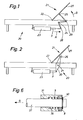
- FIG. 2 Another embodiment is shown in FIG. 2.
- the electromotive drive 23, which is firmly connected to the reclining furniture frame 20, is connected to its push or pressure pipe 3 via a swivel arm 30 mounted at the pivot point 24 with rollers 26.
- the pivotable frame part 27 rests on these rollers 26.
- These rollers 26 can be guided in a rail (not shown), so that here too the frame part 27 is forcibly guided in both directions of rotation.
- the pivoting part 27 can rest loosely on the rollers 26, so that the clockwise pivoting movement of the same takes place when the rollers 26 are lowered only by the action of gravity. It can also be seen here that a person can clamp between the same and the fixed frame part when the frame part 27 is lowered.
- FIG. 3 a sectional view of an embodiment of the electric motor drive is shown.
- the electric motor is generally designated by the reference number 7.
- the shaft of the electric motor 7 is connected to a worm 1.
- This worm 1 meshes with a worm wheel 2.
- This worm wheel is arranged on a sleeve 31.
- the sleeve 31 is supported by a roller bearing 32 in the housing 33.
- a tab 34 is connected to the housing 33 via cap screws 35.
- the drive is connected to the respective recliner furniture frame via this bracket 34.
- an annular space 36 is formed in the sleeve 31, in which an helical compression spring 9 serving as a return spring is arranged.
- the sleeve 31 is penetrated by a stub shaft 37, which with a Spindle 4 is rotatably connected.
- a truncated cone 6 is formed between the stub shaft 37 and the spindle 4, which truncated cone 6 forms a coupling half.
- the sleeve 31 has a frustoconical section 5 which overlaps the truncated cone 6 and forms the second coupling half.
- the spindle 4 runs in a sleeve 38 provided with an internal thread, via which the so-called push tube 3 is linearly displaced when the spindle 4 is rotated.
- the transmission elements which transmit the linear movement carried out by the push tube to the frame part to be adjusted, are articulated on the bracket 39.
- FIG. 4 in which a part of the sectional view of FIG. 3 is shown.
- the drive is designed in such a way that it has a safety device on tension when working on pressure.
- FIG. 1 In order to raise the frame part 27, that is to say the head part 21, the push tube 3 must exert a pressure. To pivot the frame part 27, the push tube 3 is therefore pressed by the rotation of the spindle 4 in the direction of arrow C of the lower illustration in FIG. 4. A counterforce thus arises, as is apparent to the person skilled in the art from the arrangements shown in FIGS. 1 and 2, which counterforce causes the truncated cone 6 connected to the spindle 4 to be pressed against the hollow truncated cone section 5 of the sleeve 31.
- the coupling halves 5 and 6 are in frictional engagement.
- the frame part 27 of FIG. 1 or 2 is now to be folded down.
- the direction of rotation of the spindle 4 is changed, for example, by changing the pole of the motor 7.
- the spindle now starts the thrust tube 3 from the lower position shown in FIG. 4, in which the front end of the thrust tube 3 facing the worm wheel 2 is at a distance from the housing of the motor or the worm gear against that in FIG. 4 withdraw the position shown above. If the frame part 27 is now opposed by, for example, a person jamming a limb under the frame part 27, a tensile force occurs in the push tube and thus in the spindle 4.
- the truncated cone 6 thus lifts off from the hollow truncated-cone-shaped section 5, so that there is a small space between their conical surfaces and the frictional engagement between these two coupling halves is thus eliminated.
- the frame part 27 will no longer pivot downward, although the motor 7 continues to drive. So that the pinched body part is not injured.
- FIG. 5 This figure shows an arrangement that is the reverse of that of FIG. 4, in that in the embodiment according to FIG. 5 the drive operates on a train and the fuse responds to pressure.
- the thrust tube 3 has the distance from the motor and transmission housing shown in the lower part of FIG. 5.
- the push tube 3 is pulled in the direction of arrow E.
- a counterforce thus arises again here, so that the truncated ball 6 is pulled into a frictional engagement against the frustoconical section 5. If the direction of rotation of the spindle 4 is now changed in order to pivot the frame part 27 down, the push tube 3 begins to move from the position shown in the upper part of FIG.
- FIG. 6 the Ab containing the helical compression spring 9 Section of the drive shown in FIG. 3 on an enlarged scale.
- the part of the stub shaft 37 is drawn which passes through the section of the sleeve 31 containing the helical compression spring 9.
- the helical compression spring 9 is arranged in an annular space 36 of the sleeve 31.
- a pressure bearing 8 is arranged between the front end of the sleeve 31 and a snap ring 40 seated in the stub shaft 37, here a roller bearing, ie a ball bearing.
- One race of the same rests on the sleeve 31 and the other race rests on the snap ring 40.
- the thrust bearing 8 can be inserted loosely.
- the helical compression spring 9 presses against the thrust bearing 8 and exerts a pressure on the snap ring 40.
- the two coupling halves, namely the truncated cone 6 and the frustoconical section 5 abut against one another with slight application of pressure. This ensures that there is also frictional engagement between the two coupling halves mentioned when the direction of rotation of the spindle 4 is such that the coupling is released when resistance occurs. It is evident that small frictional resistances due to the rod bearings and the pivot bearing of the pivotable frame part 27 must also be overcome in this working direction.
Landscapes
- Engineering & Computer Science (AREA)
- General Engineering & Computer Science (AREA)
- Mechanical Engineering (AREA)
- Health & Medical Sciences (AREA)
- General Health & Medical Sciences (AREA)
- Nursing (AREA)
- Chairs For Special Purposes, Such As Reclining Chairs (AREA)
- Lighting Device Outwards From Vehicle And Optical Signal (AREA)
- Orthopedics, Nursing, And Contraception (AREA)
- Gear Transmission (AREA)
- Transmission Devices (AREA)
Priority Applications (1)
| Application Number | Priority Date | Filing Date | Title |
|---|---|---|---|
| AT84115781T ATE41856T1 (de) | 1983-12-22 | 1984-12-19 | Elektromotorischer antrieb zum verstellen des kopf- oder fusskeils eines liegemoebels. |
Applications Claiming Priority (2)
| Application Number | Priority Date | Filing Date | Title |
|---|---|---|---|
| CH6863/83 | 1983-12-22 | ||
| CH6863/83A CH665942A5 (de) | 1983-12-22 | 1983-12-22 | Elektromotorischer antrieb zum verstellen des kopf- oder fusskeils eines liegemoebels. |
Publications (3)
| Publication Number | Publication Date |
|---|---|
| EP0146914A2 true EP0146914A2 (fr) | 1985-07-03 |
| EP0146914A3 EP0146914A3 (en) | 1987-04-08 |
| EP0146914B1 EP0146914B1 (fr) | 1989-04-05 |
Family
ID=4316214
Family Applications (1)
| Application Number | Title | Priority Date | Filing Date |
|---|---|---|---|
| EP84115781A Expired EP0146914B1 (fr) | 1983-12-22 | 1984-12-19 | Commande électromotrice pour le réglage du support de tête ou de jambes d'un meuble de couchage |
Country Status (4)
| Country | Link |
|---|---|
| EP (1) | EP0146914B1 (fr) |
| AT (1) | ATE41856T1 (fr) |
| CH (1) | CH665942A5 (fr) |
| DE (1) | DE3477540D1 (fr) |
Cited By (16)
| Publication number | Priority date | Publication date | Assignee | Title |
|---|---|---|---|---|
| GB2205232A (en) * | 1987-05-28 | 1988-12-07 | Egerton Hospital Equip | Bed with hinged panel safety feature |
| EP0606575A1 (fr) * | 1993-01-15 | 1994-07-20 | Dewert Antriebs- und Systemtechnik GmbH & Co. KG | Dispositif de levage |
| GB2275185A (en) * | 1993-02-02 | 1994-08-24 | Sichelschmidt Stanzwerk | An adjustable bed/seat in the form of an ottoman or recamiere |
| DE4433934A1 (de) * | 1994-09-23 | 1996-03-28 | Micas Gmbh & Co Kg | Vorrichtung zur automatischen Verstellung von Möbelteilen |
| EP0968675A1 (fr) * | 1998-06-29 | 2000-01-05 | Dewert Antriebs- und Systemtechnik GmbH & Co. KG | Entraínement pour meubles avec un électromoteur |
| EP0994553A1 (fr) * | 1998-10-12 | 2000-04-19 | Dewert Antriebs- und Systemtechnik GmbH & Co. KG | Entrainement pour meubles par moteur électrique |
| EP1231412A3 (fr) * | 2001-02-08 | 2003-08-20 | Linak A/S | Verin linéaire |
| WO2004028305A1 (fr) * | 2002-09-16 | 2004-04-08 | Dewert Antriebs- Und Systemtechnik Gmbh & Co. Kg | Entrainement de meuble par moteur electrique |
| EP1561970A3 (fr) * | 2004-02-09 | 2008-06-11 | Ludwig Ehrhardt GmbH | Actionneur linéaire |
| EP2080933A1 (fr) | 2008-01-15 | 2009-07-22 | JTEKT Corporation | Unité de vis sphérique |
| EP2172672A1 (fr) * | 2008-10-02 | 2010-04-07 | Rational AG | Dispositif d'engrenage destiné à la liaison d'une unité d'entraînement motorisée à vérin, procédé de liaison d'une unité d'entraînement motorisée à vérin et appareil de traitement de produits alimentaires |
| WO2010149558A1 (fr) * | 2009-06-23 | 2010-12-29 | Magna Powertrain Ag & Co Kg | Actionneur |
| US8375814B2 (en) | 2009-01-28 | 2013-02-19 | Stabilus Gmbh | Drive device |
| EP3657991A1 (fr) * | 2017-07-28 | 2020-06-03 | Motus Mechanics Ltd | Meubles réglables |
| IT202200011123A1 (it) * | 2022-05-26 | 2023-11-26 | Compact Italia S R L | Attuatore lineare a trazione controllata |
| US12575682B2 (en) | 2015-03-11 | 2026-03-17 | Motus Mechanics Ltd. | Adjustable furniture |
Families Citing this family (2)
| Publication number | Priority date | Publication date | Assignee | Title |
|---|---|---|---|---|
| DE102004058152C5 (de) * | 2004-12-02 | 2008-04-24 | OKIN Gesellschaft für Antriebstechnik mbH | Lagersitz und Antriebseinheit |
| DE102012211508A1 (de) * | 2012-07-03 | 2014-01-09 | Dewertokin Gmbh | Vorrichtung zur Steuerung eines Möbelantriebs |
Family Cites Families (3)
| Publication number | Priority date | Publication date | Assignee | Title |
|---|---|---|---|---|
| CH421382A (de) * | 1965-04-23 | 1966-09-30 | Altorfer Hans | Bettgestell |
| DE2622783C3 (de) * | 1976-05-21 | 1980-07-31 | Hanning Elektro-Werke Gmbh & Co, 4800 Bielefeld | Elektromechanisches Verstellgerät für den Einlegerahmen von Betten |
| CH615333A5 (en) * | 1977-04-04 | 1980-01-31 | Magnetic Elektromotoren Ag | Drive for an adjusting device of a bedstead |
-
1983
- 1983-12-22 CH CH6863/83A patent/CH665942A5/de not_active IP Right Cessation
-
1984
- 1984-12-19 AT AT84115781T patent/ATE41856T1/de not_active IP Right Cessation
- 1984-12-19 EP EP84115781A patent/EP0146914B1/fr not_active Expired
- 1984-12-19 DE DE8484115781T patent/DE3477540D1/de not_active Expired
Cited By (19)
| Publication number | Priority date | Publication date | Assignee | Title |
|---|---|---|---|---|
| GB2205232A (en) * | 1987-05-28 | 1988-12-07 | Egerton Hospital Equip | Bed with hinged panel safety feature |
| GB2205232B (en) * | 1987-05-28 | 1991-04-03 | Egerton Hospital Equip | Bed with hinged panel safety feature |
| EP0606575A1 (fr) * | 1993-01-15 | 1994-07-20 | Dewert Antriebs- und Systemtechnik GmbH & Co. KG | Dispositif de levage |
| GB2275185A (en) * | 1993-02-02 | 1994-08-24 | Sichelschmidt Stanzwerk | An adjustable bed/seat in the form of an ottoman or recamiere |
| GB2275185B (en) * | 1993-02-02 | 1996-11-06 | Sichelschmidt Stanzwerk | An adjustable bed/seat |
| DE4433934A1 (de) * | 1994-09-23 | 1996-03-28 | Micas Gmbh & Co Kg | Vorrichtung zur automatischen Verstellung von Möbelteilen |
| EP0968675A1 (fr) * | 1998-06-29 | 2000-01-05 | Dewert Antriebs- und Systemtechnik GmbH & Co. KG | Entraínement pour meubles avec un électromoteur |
| EP0994553A1 (fr) * | 1998-10-12 | 2000-04-19 | Dewert Antriebs- und Systemtechnik GmbH & Co. KG | Entrainement pour meubles par moteur électrique |
| EP1231412A3 (fr) * | 2001-02-08 | 2003-08-20 | Linak A/S | Verin linéaire |
| WO2004028305A1 (fr) * | 2002-09-16 | 2004-04-08 | Dewert Antriebs- Und Systemtechnik Gmbh & Co. Kg | Entrainement de meuble par moteur electrique |
| EP1561970A3 (fr) * | 2004-02-09 | 2008-06-11 | Ludwig Ehrhardt GmbH | Actionneur linéaire |
| EP2080933A1 (fr) | 2008-01-15 | 2009-07-22 | JTEKT Corporation | Unité de vis sphérique |
| US8424402B2 (en) | 2008-01-15 | 2013-04-23 | Jtekt Corporation | Ball screw unit |
| EP2172672A1 (fr) * | 2008-10-02 | 2010-04-07 | Rational AG | Dispositif d'engrenage destiné à la liaison d'une unité d'entraînement motorisée à vérin, procédé de liaison d'une unité d'entraînement motorisée à vérin et appareil de traitement de produits alimentaires |
| US8375814B2 (en) | 2009-01-28 | 2013-02-19 | Stabilus Gmbh | Drive device |
| WO2010149558A1 (fr) * | 2009-06-23 | 2010-12-29 | Magna Powertrain Ag & Co Kg | Actionneur |
| US12575682B2 (en) | 2015-03-11 | 2026-03-17 | Motus Mechanics Ltd. | Adjustable furniture |
| EP3657991A1 (fr) * | 2017-07-28 | 2020-06-03 | Motus Mechanics Ltd | Meubles réglables |
| IT202200011123A1 (it) * | 2022-05-26 | 2023-11-26 | Compact Italia S R L | Attuatore lineare a trazione controllata |
Also Published As
| Publication number | Publication date |
|---|---|
| DE3477540D1 (en) | 1989-05-11 |
| CH665942A5 (de) | 1988-06-30 |
| EP0146914B1 (fr) | 1989-04-05 |
| EP0146914A3 (en) | 1987-04-08 |
| ATE41856T1 (de) | 1989-04-15 |
Similar Documents
| Publication | Publication Date | Title |
|---|---|---|
| EP0146914B1 (fr) | Commande électromotrice pour le réglage du support de tête ou de jambes d'un meuble de couchage | |
| DE10017978C2 (de) | Möbelantrieb | |
| DE10031737C2 (de) | Möbelantrieb zum Verstellen von Teilen eines Möbels relativ zueinander | |
| EP2974622A1 (fr) | Dispositif d'appui reglable a moteur electrique | |
| DE102014115033A1 (de) | Elektromotorisch verstellbare Stützeinrichtung | |
| EP0364394A2 (fr) | Lit permettant d'ajuster le support des jambes d'une personne | |
| DE102020131206A1 (de) | Elektromotorisch verstellbare Stützeinrichtung | |
| EP3400834A1 (fr) | Ferrure pivotante et meuble | |
| CH683496A5 (de) | Antrieb zum Verstellen eines bewegbaren Teils einer Einrichtung. | |
| EP3954255B1 (fr) | Dispositif d'appui à réglage par moteur électrique | |
| DE102020131204A1 (de) | Elektromotorisch verstellbare Stützeinrichtung | |
| DE4037289A1 (de) | Vorrichtung zum spannen eines treibriemens | |
| DE102007059457A1 (de) | Lastsensitive Antriebskraftübertragungseinrichtung | |
| DE102016116255A1 (de) | Elektromotorischer Möbelantrieb | |
| DE3043665A1 (de) | Halte- und fuehrungsvorrichtung fuer die stoffdrueckerstange von einer naehmaschine | |
| DE10046752C1 (de) | Als Doppelantrieb ausgebildeter Möbelantrieb | |
| DE102004016050B4 (de) | Elektromotorischer Möbelantrieb zum Verstellen von Teilen eines Möbels relativ zueinander | |
| DE2500457C2 (de) | Skibindungsteil | |
| DE202021002184U1 (de) | Matratzenunterfederung mit motorischer Kniewinkelverstellung | |
| DE202021104109U1 (de) | Elektromotorisch verstellbare Stützeinrichtung | |
| DE29902989U1 (de) | Manuelle Verstelleinrichtung eines Antriebes | |
| DE834657C (de) | Selbsttaetiges Geschwindigkeitswechselgetriebe fuer Leichtfahrzeuge, wie Fahrraeder mit Hilfsmotor od. dgl. | |
| DE864538C (de) | Nachgiebiger Grubenstempel | |
| EP1285645A2 (fr) | Elévateur de bain pour personnes âgées et handicapés | |
| DE29600721U1 (de) | Elektromotorischer Möbelantrieb |
Legal Events
| Date | Code | Title | Description |
|---|---|---|---|
| PUAI | Public reference made under article 153(3) epc to a published international application that has entered the european phase |
Free format text: ORIGINAL CODE: 0009012 |
|
| AK | Designated contracting states |
Designated state(s): AT BE CH DE FR GB IT LI LU NL SE |
|
| PUAL | Search report despatched |
Free format text: ORIGINAL CODE: 0009013 |
|
| AK | Designated contracting states |
Kind code of ref document: A3 Designated state(s): AT BE CH DE FR GB IT LI LU NL SE |
|
| 17P | Request for examination filed |
Effective date: 19870926 |
|
| 17Q | First examination report despatched |
Effective date: 19880603 |
|
| GRAA | (expected) grant |
Free format text: ORIGINAL CODE: 0009210 |
|
| ITF | It: translation for a ep patent filed | ||
| AK | Designated contracting states |
Kind code of ref document: B1 Designated state(s): AT BE CH DE FR GB IT LI LU NL SE |
|
| PG25 | Lapsed in a contracting state [announced via postgrant information from national office to epo] |
Ref country code: SE Effective date: 19890405 Ref country code: NL Effective date: 19890405 Ref country code: GB Effective date: 19890405 Ref country code: BE Effective date: 19890405 |
|
| REF | Corresponds to: |
Ref document number: 41856 Country of ref document: AT Date of ref document: 19890415 Kind code of ref document: T |
|
| REF | Corresponds to: |
Ref document number: 3477540 Country of ref document: DE Date of ref document: 19890511 |
|
| ET | Fr: translation filed | ||
| NLV1 | Nl: lapsed or annulled due to failure to fulfill the requirements of art. 29p and 29m of the patents act | ||
| GBV | Gb: ep patent (uk) treated as always having been void in accordance with gb section 77(7)/1977 [no translation filed] | ||
| PG25 | Lapsed in a contracting state [announced via postgrant information from national office to epo] |
Ref country code: AT Effective date: 19891219 |
|
| PG25 | Lapsed in a contracting state [announced via postgrant information from national office to epo] |
Ref country code: LU Free format text: LAPSE BECAUSE OF NON-PAYMENT OF DUE FEES Effective date: 19891231 |
|
| PLBE | No opposition filed within time limit |
Free format text: ORIGINAL CODE: 0009261 |
|
| STAA | Information on the status of an ep patent application or granted ep patent |
Free format text: STATUS: NO OPPOSITION FILED WITHIN TIME LIMIT |
|
| 26N | No opposition filed | ||
| PGFP | Annual fee paid to national office [announced via postgrant information from national office to epo] |
Ref country code: FR Payment date: 19921125 Year of fee payment: 9 |
|
| PGFP | Annual fee paid to national office [announced via postgrant information from national office to epo] |
Ref country code: DE Payment date: 19921211 Year of fee payment: 9 |
|
| ITTA | It: last paid annual fee | ||
| PG25 | Lapsed in a contracting state [announced via postgrant information from national office to epo] |
Ref country code: FR Effective date: 19940831 |
|
| PG25 | Lapsed in a contracting state [announced via postgrant information from national office to epo] |
Ref country code: DE Effective date: 19940901 |
|
| REG | Reference to a national code |
Ref country code: FR Ref legal event code: ST |
|
| PGFP | Annual fee paid to national office [announced via postgrant information from national office to epo] |
Ref country code: CH Payment date: 19941216 Year of fee payment: 11 |
|
| PG25 | Lapsed in a contracting state [announced via postgrant information from national office to epo] |
Ref country code: LI Effective date: 19951231 Ref country code: CH Effective date: 19951231 |
|
| REG | Reference to a national code |
Ref country code: CH Ref legal event code: PL |