EP0147936A2 - Nachrichtenanzeigegerät - Google Patents
Nachrichtenanzeigegerät Download PDFInfo
- Publication number
- EP0147936A2 EP0147936A2 EP84307832A EP84307832A EP0147936A2 EP 0147936 A2 EP0147936 A2 EP 0147936A2 EP 84307832 A EP84307832 A EP 84307832A EP 84307832 A EP84307832 A EP 84307832A EP 0147936 A2 EP0147936 A2 EP 0147936A2
- Authority
- EP
- European Patent Office
- Prior art keywords
- message
- status
- display
- displayed
- messages
- Prior art date
- Legal status (The legal status is an assumption and is not a legal conclusion. Google has not performed a legal analysis and makes no representation as to the accuracy of the status listed.)
- Granted
Links
Images







Classifications
-
- G—PHYSICS
- G09—EDUCATION; CRYPTOGRAPHY; DISPLAY; ADVERTISING; SEALS
- G09G—ARRANGEMENTS OR CIRCUITS FOR CONTROL OF INDICATING DEVICES USING STATIC MEANS TO PRESENT VARIABLE INFORMATION
- G09G3/00—Control arrangements or circuits, of interest only in connection with visual indicators other than cathode-ray tubes
-
- G—PHYSICS
- G06—COMPUTING OR CALCULATING; COUNTING
- G06F—ELECTRIC DIGITAL DATA PROCESSING
- G06F3/00—Input arrangements for transferring data to be processed into a form capable of being handled by the computer; Output arrangements for transferring data from processing unit to output unit, e.g. interface arrangements
- G06F3/14—Digital output to display device ; Cooperation and interconnection of the display device with other functional units
- G06F3/147—Digital output to display device ; Cooperation and interconnection of the display device with other functional units using display panels
Definitions
- the present invention relates to a message display device for displaying a message representing the operating status of and/or operating instructions for an electronic apparatus such as a copying machine, a facsimile machine, a word processor, a printer or the like (hereinafter simply referred to as "a copying machine or the like"), in which the language to be displayed can be easily changed and the contents of the. message to be displayed can be readily altered without changing message-display control software.
- a message display device provided with a display section constituted by message display tubes or a message display panel at a console section of a copying machine or the like, whereby a message representing the status of and/or operating instructions for the copying machine or the like is selected in accordance with a program of a control ROM from among messages stored in the form of character strings in a message ROM of a message display control section, and the thus-selected message is displayed on a display section of the console section.
- the kinds of message to be displayed can be increased in accordance with the capacity of the message ROM so that the status of and/or operating instructions for the copying machine or the like can be fully elaborated to provide an excellent operating capability for the operator.
- a message display device for displaying a message representing the status of and/or operating instructions for an electronic apparatus, said device comprising:
- the status memory means may store, for every unit display, message numbers of messages to be displayed and corresponding output formats of the messages.
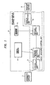
- Fig. 1 shows a first embodiment of the present invention.
- the message display device includes an apparatus control section 1, a message display controller 2 having a status judgement/control unit 3, a status memory 4, a message memory 5, and a message display section 6.
- the apparatus control section 1 acts to control the operation of an electronic apparatus such as a copying machine or the like and produces a control signal, hereinafter referred to as a status signal, in accordance with the operating status of the machine, conditions of paper jam, lack of copying paper, shortage of toner, etc., or operating instructions, for example, the setting of the number of copies, the setting of a reduction/magnification factor, etc.
- the message-display controller 2 is used for informing the message display section 6 of the message to be displayed in accordance with the status signal and for judging the status in response to the status signal generated by the status judgement/control unit. On the basis of the result of this judgement, the message number of the message to be displayed corresponding to the judged status is read out from the status memory 4, the message to be displayed corresponding to the detected message number is selected out of message memory 5, and an instruction is issued to the message display section 6 to instruct it to display the selected message.
- the message display control section 2 is constituted by the three sections as described above.
- a judgement section 7 judges the status in response to the status signal
- a message-number detecting section 8 detects the message number of the message to be displayed
- a message selecting section 9 selects the message corresponding to the message number
- a display instruction section 10 issues an output instruction.
- the status memory 4 stores messages to be displayed in the form of message number, each message corresponding to a particular case where display is to be effected, each case including a message to be displayed in accordance with a status.
- the message memory 5 stores messages to be displayed and serial numbers, that is, message numbers, defined corresponding to the messages.
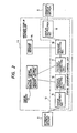
- Fig. 2 shows a second embodiment of the present invention.
- This arrangement differs from that shown in Fig. 1 in that a status memory stores output formats as well as message numbers, and that a status judgement/controller has an output-format detecting section 17.
- the output format is used for controlling the display format of the message in the case where it is necessary to display two or more messages in accordance with the status of an apparatus, in the case where it is required to change the kind of message to be displayed depending on the level of skill of the operator, or in the case where it is necessary to change the period of display and/or the number of times of display depending on the length or importance of the message.
- the mode of message display is made selectable in accordance with the status of the apparatus on the basis of the output format detected by the output-format detecting section 17.
- the status is judged by a status signal from an apparatus control section 1.
- the message number of the message to be displayed corresponding to the status is read out from a status memory 13, and the output format is detected by the output format detector 17.
- the message to be displayed corresponding to the detected message number is selected from a message memory 14, and an output instruction to display the selected message with the detected format is issued to a message display section 6.
- the arrangement described above is featured in that the apparatus control section 1 is separated from the message-display controller 2/11, in that the message-display controller 2/11 is provided with three components, that is, the message memory 5/14, the status memory 4/13, and the status judgement/control unit 3/12, and in that the status judgement/control unit 3/12 and the message memory 5/14 are accessible using message numbers of the status memory 4/13.
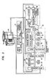
- Fig. 3 shows an embodiment of the arrangement of Fig. 1 which includes a message display section 22 provided on a console 21 of a copying machine 20, a copying-machine control section (microcomputer) 23 for controlling the copying machine 20, a message-display control section 24 receiving a status signal from the control section 23 and producing a display signal in accordance with the status signal, and a drive section 25 for causing the message display section 22 of the console 21 to display a predetermined message on the basis of the display signal form the message-display control section 24.
- the copying-machine control section 23 includes a microcomputer having an input/output interface 26, a program ROM 27, a CPU 28, and an operation-result storing RAM 29.
- the control section 23 receives a sensor signal from the copying machine 20 and an operator-instruction signal from the console 21 and produces a control signal for controlling the operation of the copying machine 20 and a status signal in accordance with the status of the copying machine 20.
- the message-display control section 24 includes an input/output port 31 for fetching the status signal, a status judgement/control unit 32 for judging the status on the basis of the status signal to thereby control the message to be displayed, a message ROM 33 having a message memory 33a storing messages to be displayed and message numbers defined corresponding to the messages and a status memory 33b storing message numbers of the messages to be displayed by the unit of display, and a character generator 34 generating output display signals, for instance, in the well-known 5 x 7 format, for generating character patterns of the message to be displayed.
- the drive section 25 is implemented with a shift register 39 controlled by a timing signal of a timing counter 38 for producing a drive signal in accordance with the character pattern of the character generator 34, an X-driver 40 for dot-lighting a display panel 22 in response to the drive signal of the shift register 39, a decoder 41 for providing a timing signal from which is produced a drive signal in accordance with the drive lighting, and a Y-driver 42 for causing the character pattern of the character generator 34 to be dynamically displayed on the basis of the drive signal of the decoder 41.
- the status judgement/control unit 32 of the message-display control section 24 is constituted by a message control ROM 35 storing programs for processing the status signal to -thereby determine the message to be displayed, a CPU 36 for computing/executing the programs, and an output RAM 37 for storing the result of computing.
- the message ROM 35 is constituted by three modules, that is, a real time monitor 43, a case selection module 44, and a display module 45.
- the real time monitor 43 stores programs for executing the following:
- the case selection module 44 stores programs for executing the following:
- the display module 45 stores programs for executing the following:
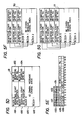
- Figs. 5A to 5G show the arrangement of the message ROM 33 implementing the message memory and the status memory.
- Fig. 5A show an overall memory map of the message ROM 33, the memory area of which is divided among a management section 46, a status memory (hereinafter referred to as a case table) 47, and a message memory 48.
- Fig. 5A show an overall memory map of the message ROM 33, the memory area of which is divided among a management section 46, a status memory (hereinafter referred to as a case table) 47, and a message memory 48.
- 5B shows the management section 46, which includes a total stored-message number area 461 storing the number of messages to be displayed, a case table start LOW address storing area 462 storing respective start LOW addresses of case tables provided for every unit display for instructing the status of and operation for the copying machine, and a message-storing-area start address storing area 463 storing start addresses of the area in which messages to be displayed are stored.
- messages are allocated to storing areas by the number of characters such that the smallest message number of messages of 41 to 60 characters is stored in an area 464 and the smallest message number of messages of 61 to 80 characters is stored in an area 465.
- Fig. 5C shows a case table.
- Such case tables are prepared by the number corresponding to the possible statuses of the copying machine on the assumption that a message to be displayed in accordance with a status of the copying machine is regarded as one unit. For example, if there are provide 120 messages corresponding to various statuses of the copying machine, there are provided 120 case tables.
- Fig. 5C shows a single case table in which an area stores the message number of a message to be displayed corresponding to a status.
- Figs. 5D, 5F and 5G show the arrangement of the message memory section 48 in which messages are stored in areas in accordance with the number of characters of the respective message. This is done due to a limitation on the number of characters of the message which can be displayed.
- Fig. 5D shows a message memory 49 storing messages of 1 to 40 characters. The memory 49 sores messages to be displayed each having a serial number, that is, an individual message number. In order to reduce the messages to be displayed in number, messages each having a blank portion are also stored so that these messages can be rewritten by an input signal from the console 21.
- a message representing a reduction/magnification factor for example, a message such as "READY TO ENLARGE %, PUSH 'START'" as shown in Fig. 5E (which has a blank portion) is stored so that the reduction/magnification factor, for example, 141%, can be rewritten into the blank portion in response to a reduction/magnification factor signal from the console 21.
- the message memory 49 as shown in Fig. 5D has areas 491 and 493 each storing rewriting start byte portions of five bits, areas 492 and 494 each storing the number of rewriting bytes of three bits, and message character sections 495 and 496, respectively, having 20- byte areas for block 0 and 1 messages of 40 characters.
- the upper areas 491 and 492 control the block 0 of the area 495, and the lower areas 493 and 494 control the block 1 of the area 496.
- Fig. 5E shows an example of a control sequence in which the rewriting start byte position of the block 0 of the area 495 is determined by a code (00000) of the area 491 and the number of rewriting bytes is determined by a code (011) of the area 492.
- Figs. 5F and 5G show message memories 50 and 51 storing messages of 60 characters and messages of 80 characters, respectively.
- the above-mentioned message number is a serial number given to every message such that each message number corresponds to one specific message.
- each message number corresponds to one specific message.
- the device In the case it is intended to enable the device to display a message with a selected one of various languages, for example, when display is to be performed in Japanese for a copying machine for Japan while in English for the United States, one and the same message number is given to the messages having the same meaning. This is done because that message number is used for access in the message display device and because doing so makes it possible to perform display without changing the status judgement/control unit and the case table.
- a status signal corresponding to the status is applied to the message-display control section 24 under the synchronized condition by a transfer synchronizing signal (information reception). If there is no abnormality such as noise in the received status signal, the reception is judged to be normal.
- the status signal is processed in the CPU 36 on the basis of the program of the message control ROM 35 of the message-display control section 24 so that the present case is appropriately determined corresponding to the status signal.
- a case table (Fig. 5C) corresponding to the present case is read out of the message ROM 33 and applied to the output RAM 37.
- the output RAM 37 is constituted by an editing RAM and a display RAM.
- the reading out of this case table is performed using an address determined on the basis of storage of the area 462 of the management section 46.
- the message storage address of the message memory section 48 is computed from the message number of the case table on the basis of the above-mentioned case determination and what is stored in the area 463 of the case table 46. On the basis of the result of this computing, the corresponding message is read into the editing RAM.
- a character code of the message is sent from the display RAM to the character generator 34 which then generates a character pattern, which is in turn read out and applied to the shift register 39.
- the shift register 39 drives the X-driver 40 and Y-driver 42 and performs dynamic control such that the message is displayed by the display section 22 for a predetermined period of time.
- the display modes include the following:
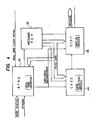
- Fig. 7 shows an embodiment of the arrangement of Fig. 2, which includes a message display section 22, a copying-machine control section 23, and a drive section 25. Since these sections are the same as those shown in Fig. 3, a further description thereof is omitted here.
- the same reference numerals as those used in Fig. 3 are used here to represent the same components.
- a message-display control section 52 includes an input/output port 31 receiving a status signal; a message control ROM 53 ' storing programs for processing the status signal to determine the message number, etc., for the message to be displayed, a message ROM 54 storing case tables, etc., or predetermined messages to be displayed in the form of trains of character codes; a CPU 55 for processing the status signal on the basis of the program of the message control ROM 53, reading a message out of the message ROM 54 on the basis of an address determined on the basis of the message number of a message corresponding to the status of the copying machine 20, and for determining the display code of the read-out message (for example, a display format as to whether the message be displayed at the same time or be displayed in a scroll mode, the display timing, the display time, etc.,); an editing RAM 56 for editing the message read out of the message ROM 54 into a message to be displayed; a display RAM 57 for storing for display the message edited by the editing RAM 57; a non-display timer
- the message control ROM 53 has, in a case selection module, a program for setting output formats, and the message ROM 54 contains, for every case, the message numbers of messages to be displayed together with the output formats thereof. Further, the console 21 is provided with a help button 65 for requesting a help message.
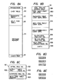
- Fig. 8A to 8L show the arrangement of the message ROM 54.
- Fig. 8A shows an overall memory map including a management section 59, a case table 60, a diagnostic table section 6, a help tree table 62, a message memory section 63, and a check sum 64. Description will be made as to the individual components.
- Fig. 8A shows an overall memory map including a management section 59, a case table 60, a diagnostic table section 6, a help tree table 62, a message memory section 63, and a check sum 64. Description will be made as to the individual components.
- Fig. 8A shows an overall memory map including a management section 59, a case table 60, a diagnostic table section 6, a help tree table 62, a message memory section 63, and a check sum 64. Description will be made as to the individual components.
- Fig. 8A shows an overall memory map including a management section 59, a case table 60, a diagnostic table section 6, a help tree table 62,
- 8B shows the management section 59 including a total message-number storing area 591 which stores the number of messages to be displayed, a case-table start LOW address storing area 592 which stores start LOW addresses of a case table provided for every case indicating the status of and/or operation for the copying machine, a diagnostic table start address storing area 593 storing addresses of a diagnostic table which is provided for every diagnostic mode necessary for maintenance of the copying machine or the like and which stores message numbers of diagnostic messages, a help tree table start address storing area 594 - which stores start addresses of a help tree table storing the message numbers of help messages to be displayed upon depression of the help button 65 by the operator, a message-storing-area start address storing area 595 storing start addresses of the area which stores-messages to be displayed, a 60-character-message smallest message number storing area 596 storing the smallest message number of messages of 41 to 60 characters, a 80-character-message smallest message number storing area 597 storing the smallest
- Fig. 8C shows a case table provided for every case in which the status of and/or operating instruction for the copying machine is judged on the basis of the program of the message control ROM 53.
- an area 601 stores initial-message numbers of messages to be displayed corresponding to the various possible cases
- an area 602 stores the kind of an alternate mode (a mode in which a plurality of messages are displayed alternately)
- an area 603 stores message rank numbers defining a display message on the basis of the number of times of depressing of the help button when the operator depresses the help button 65 in accordance with the status of the copying machine
- an area 604 stores message numbers of alternate messages to be alternately displayed in place of an initial message
- an area 605 stores help tree pointers designating help tree tables which will be described later.
- a mode of fixed display display of only an initial message
- another mode of alternate-l display two messages, that is an initial message and an alternate message, are alternately displayed for 60 seconds
- a further mode of alternate-2 display two messages, that is an initial message and an alternate message, are alternately displayed three times
- FIG. 8F shows the diagnostic table 61 for indexing a diagnostic message number in which message numbers correspond to the respective diagnostic cases 0, 1, 2 ... n.
- Fig. 8G shows the help tree table 62 which stores message numbers of the messages, corresponding to the number of times of depression of the help button 65, in the order of the ranks 1, 2, ... n, and which is provided with an area 621 storing a message number of a help message first produced at each of the respective ranks and another area 622 storing message numbers of messages, each of which is alternately displayed with a help message.
- Figs. 8H, 8I, 8J and 8K show the message memory section, which is arranged in the same manner as that shown in Figs. 5D, 5F and 5G.
- Fig. 8L shows the relation among the areas described above. This relation is apparent from the drawing, and therefore a further description will be omitted.
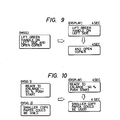
- Figs. 9 and 10 show message display modes.
- Fig. 9 shows a scroll mode
- Fig. 10 shows an alternate mode.
- the message is divided into a plurality of, for example, two, portions which are time-divisionally displayed.
- a message to be displayed "LIFT GREEN HANDLE ON LEFT SIDE AND OPEN COPIER” is divided into two portions “LIFT GREEN HANDLE ON LEFT SIDE AND” and "OPEN COPIER", and each of the two portions is displayed for 4 seconds.
- the alternate mode on the other hand, for example, a first or initial message "READY TO ENLARGE ... 141% PUSH 'START'" and a second or alternate message "SMALLER COPY PAPER COULD BE USED" are alternately displayed each for 4 seconds.
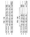
- Figs. 11A and 11B illustrate two kinds of alternate modes.
- Fig. 11A illustrates the above-mentioned alternate-2 display mode in which, after a first message 1 and a second message 2 are alternately displayed three times, each for 4 seconds, the first message 1 or the second message 2 is finally fixedly displayed.
- Fig. 11B depicts the above-mentioned alternate-1 display mode in which, after a first message 1 and a second message 2 are alternately displayed each for 4 seconds during a 60 second period, the first message 1 or the second message 2 is finally fixedly displayed.
- Fig. 11A illustrates the above-mentioned alternate-2 display mode in which, after a first message 1 and a second message 2 are alternately displayed three times, each for 4 seconds, the first message 1 or the second message 2 is finally fixedly displayed.
- Fig. 11B depicts the above-mentioned alternate-1 display mode in which, after a first message 1 and a second message 2 are alternately displayed each for 4 seconds during a 60 second period
- Figs. 12A to 12D show the help mode.
- This help mode is employed when measures needed to be applied to the copying machine cannot be understood by only initial or alternate messages.
- a message for explaining the needed measures in detail is displayed as a help message.
- Such a help message may be advantageously requested on one occasion and not on another occasion depending on the level of skill of the operator, and therefore the help mode display is only started upon depression of the help button 65 on the console 21 of the copying machine 20.
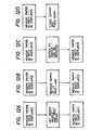
- Figs. 12A to 12D show examples of output messages to be displayed when a paper jam has occurred in the copying machine.
- the message are as follows:
- the message A is an initial message which is to be intially displayed in accordance with the status of the copying machine, while messages B to E are help messages which are to be displayed upon depression of the help button 65.
- messages B to E are help messages which are to be displayed upon depression of the help button 65.
- the message A is displayed.
- the message A is displayed again (Fig. 12A).
- the message C is displayed, and thereafter the message A is displayed again (Fig. 12B).
- the operator does not yet understand the needed measure upon reading the messages A to C, he may again push the help button 65 (the third depression) so that the message D is displayed. Thereafter, the message A is displayed again (Fig. 12C).
- the message E is displayed and the help display is terminated with the display of the message E because there is no further help message (Fig. 12D).
- the help system is arranged such that the help message displayed on depression of the help button 65 is changed depending on the number of times of depression and such that the help rank numbers or the number of times of depression of the help button and the help tree table pointer or the message numbers of messages to be displayed in accordance with the number of times of depression are stored in the areas 603 and 605 in the case table section 60 as shown in Fig. 8C so that a help messages stored in the help tree table section 62 is displayed on the basis of this case table.
- a status signal corresponding to the status is outputted synchronously to the message-display control section 52 synchronized (information reception). If there is no abnormality present such as noise in the received status signal, the reception is judged to be normal during received information checking.
- the status signal is processed in the CPU 55 on the basis of the program of the message control ROM 52 .of the message-display control section 52 so that a present case is determined corresponding to the status signal.
- a case table (Fig. 8C) corresponding to the case is read out of the message ROM 54 and applied to the editing RAM 57, and at the same time, the help tree table (Fig. 8G) is read out on the basis of the help table pointer of the area 605 of the case table and applied to the editing RAM 56.
- the reading-out of these cases and help tree tables is performed in accordance with addresses determined on the basis of the content of the areas 592 and 594 of the management table (Fig. 8B).
- the address of the message corresponding ta the initial message number of the case table area 601 is determined on the basis of the above-mentioned determination of case and the storage of the areas 595, 596 and 597 in the management section 59.
- a message to be displayed is edited on the basis of the output mode 602 of the case table, the help rank number 603, rewriting memory contents 631 and 632 of the message memory section 63.
- the message to be displayed is written into the display RAM 57.
- a 4 - second timer for performing the alternate display is set (similarly, the 4-second timer is set when it is necessary to effect scroll display, and the number of times of alternate display is counted by a counter when 3-times alternate display is performed).
- the character generator 34 produces a character pattern which is read into the shift register 39.
- the shift register 39 drives the X-driver 40 and Y-driver 42, which perform control of the dynamic lighting, so that the initial message is displayed by the display section 22.
- the alternate message is read out and displayed at the display section 22 in the same manner as above.
- Which one of the alternate modes selected between those shown in Figs. llA and 11B is determined on the basis of the contents of the area 602 of the case table (Fig. 8D).
- the message to "be fixedly displayed upon completion of the alternate display is determined also on the basis of the contents of this area 602 (Fig. 8E). Further, on the basis of the contents of the area 603 of the case table, the display of the help messages as shown in Figs. 12A to 12D is controlled.
- a message address bias for example, corresponding to four addresses, is added, and the last half of the message is read out from the message ROM 54 into the display RAM 57 through the editing RAM 56 and then outputted therefrom, and the 4-second timer is newly set.
- the address of the message which is not now being displayed is obtained on the basis of the initial message number and the alternate message number so that the message is read out of the message ROM 54 into the display RAM 57 through the editing RAM 56 and then outputted in the same manner as above, and the 4-second timer is newly set.
- a message is displayed in one of the various output formats in accordance with the status signal.
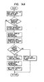
- description will be made with respect to the display output routine (Fig. 14A), the time-out routine (Fig. 14B) of the non-display timer 58 of the message-display control section 52, and the time-out routine (Fig. 14C) of a message output timer (not shown).
- Fig. 14A a message to be displayed is read out of the message ROM 54 into the editing RAM 56 and, if it is necessary to rewrite the message, rewriting is effected as shown in Figs. 8H and 8I.
- the non-display timer 58 is operating when the message to be displayed has been written into the display RAM 57, the non-display timer 58 and the display-inhibition instruction are cleared and the message output timer is set to 4-seconds. The message to be displayed is displayed for these 4 seconds by the display section 22. If the non-display timer 58 is not operating when the message to be displayed has been written into the display RAM 57, on the other hand, the non-display timer 58 is set to 250 milliseconds in order to avoid the influence of the residual image of the preceding display.
- the message output timer is set in accordance with Fig. 14B. This is effected by the message which is now being displayed on the basis of the count of the alternate counter and the existence of an alternate mode. In the case only an initial message is being fixedly displayed, the count of the alternate counter is zero, and since the alternate mode is "0" or does not exist, the message output timer is not set. In the case of an alternate message, on the other hand, the count of the alternate counter is not zero and the message output timer is set. In the case of a scroll display message, since the alternate mode is not "0" while the count of the alternate counter is zero, the message output timer is set.
- the count of the alternate counter is not zero and the message output timer is set in the same manner as above.
- the display inhibition instruction is released and the operation is shifted again to Fig. 14A.
- Fig. 14C shows a flowchart for selecting a message to be displayed next in which a character processing command is checked, and in the case where a message is being displayed in the scroll mode. If the character processing command is not "0", that is, when the message being displayed has 40 or less characters, 40 is added to the message address in order to index 41 to 80 characters. In the case where the character processing command is zero, since the scroll mode has been terminated, the operation is shifted to the alternate processing routine and the message number of a message to be displayed next or the message number of a message to be fixedly displayed is determined.
- the message memory (the message ROM 33/54) need be changed.
- one and the same message number is given to all messages having the same meaning.
- messages to be displayed and/or output formats thereof are changed because of changes in specification, etc., of the apparatus, only the by-status- message memory is changed. That is, since a message corresponding to one case is stored in each of a plurality of message ROMs corresponding to respective various languages with one and the same message number, it is sufficient for the CPU 36/55 to use the single program of the message ROM 35/53.
- the help message "LIFT GREEN HANDLE ON LEFT SIDE AND OPEN COPIER” is altered into “LIFT RED HANDLE ON LEFT SIDE AND OPEN COPIER”, or in more detail, the help message "REMOVE ALL PAPER IN COPIER” is altered to "REMOVE PAPER AT LOCATION A IN COPIER", the altered message is stored in the message ROM with the same message number as that of the initial message so that the CPU 36/55 can read a message corresponding to the case at hand from the message ROM 33/54 on the basis of the common program of the message control ROM 35/53.
- the message display device is arranged such that an apparatus control section for controlling a copying machine or the like and a message-display control section for controlling messages to be displayed are separated from each other, and the message-display control section is divided into a message, a status memory, and a status judgement/control unit so that the message memory and the status judgement/control unit can be accessed by a message number of the status memory.
Landscapes
- Engineering & Computer Science (AREA)
- Theoretical Computer Science (AREA)
- Physics & Mathematics (AREA)
- General Physics & Mathematics (AREA)
- Computer Hardware Design (AREA)
- Human Computer Interaction (AREA)
- General Engineering & Computer Science (AREA)
- Digital Computer Display Output (AREA)
- Controls And Circuits For Display Device (AREA)
- Control Or Security For Electrophotography (AREA)
- Document Processing Apparatus (AREA)
- Storing Facsimile Image Data (AREA)
Applications Claiming Priority (2)
| Application Number | Priority Date | Filing Date | Title |
|---|---|---|---|
| JP58213663A JPS60104992A (ja) | 1983-11-14 | 1983-11-14 | 文章表示装置 |
| JP213663/83 | 1983-11-14 |
Publications (3)
| Publication Number | Publication Date |
|---|---|
| EP0147936A2 true EP0147936A2 (de) | 1985-07-10 |
| EP0147936A3 EP0147936A3 (en) | 1987-09-30 |
| EP0147936B1 EP0147936B1 (de) | 1992-06-03 |
Family
ID=16642893
Family Applications (1)
| Application Number | Title | Priority Date | Filing Date |
|---|---|---|---|
| EP84307832A Expired EP0147936B1 (de) | 1983-11-14 | 1984-11-13 | Nachrichtenanzeigegerät |
Country Status (3)
| Country | Link |
|---|---|
| EP (1) | EP0147936B1 (de) |
| JP (1) | JPS60104992A (de) |
| DE (2) | DE3485760T2 (de) |
Cited By (6)
| Publication number | Priority date | Publication date | Assignee | Title |
|---|---|---|---|---|
| FR2611947A1 (fr) * | 1987-02-27 | 1988-09-09 | Smh Alcatel | Machine a affranchir comportant une alarme |
| EP0281862A1 (de) * | 1987-02-27 | 1988-09-14 | Neopost Industrie | Betriebssystem für eine elektronische Frankiermaschine |
| EP0192119B1 (de) * | 1985-02-06 | 1990-07-25 | Kabushiki Kaisha Toshiba | Bilderzeugungsgerät mit Bedienungspultkontrollfunktion |
| EP0335962A4 (en) * | 1987-10-13 | 1990-12-05 | Motorola, Inc. | Electronic display system |
| CH682785GA3 (de) * | 1985-10-30 | 1993-11-30 | Mitsubishi Electric Corp | Anzeigesteuereinrichtung für einen Aufzug. |
| US5309174A (en) * | 1987-10-13 | 1994-05-03 | Motorola, Inc. | Electronic display system |
Families Citing this family (7)
| Publication number | Priority date | Publication date | Assignee | Title |
|---|---|---|---|---|
| JPS6234274A (ja) * | 1985-08-07 | 1987-02-14 | Sharp Corp | ワ−ドプロセッサ |
| JPS6289987A (ja) * | 1985-10-16 | 1987-04-24 | 富士ゼロックス株式会社 | 文章表示装置 |
| JPS62188793U (de) * | 1986-05-21 | 1987-12-01 | ||
| JPS63194392U (de) * | 1987-06-01 | 1988-12-14 | ||
| JPH0758426B2 (ja) * | 1987-07-20 | 1995-06-21 | 富士通テン株式会社 | 電話機の表示制御装置 |
| JP2571725B2 (ja) * | 1990-09-18 | 1997-01-16 | 東京特殊電線株式会社 | Crtディスプレイ装置 |
| JPH04119062A (ja) * | 1990-09-10 | 1992-04-20 | Fuji Xerox Co Ltd | 異常処理教示装置 |
Family Cites Families (4)
| Publication number | Priority date | Publication date | Assignee | Title |
|---|---|---|---|---|
| JPS5826032B2 (ja) * | 1977-03-15 | 1983-05-31 | 株式会社東芝 | メツセ−ジ表示方式 |
| US4381505A (en) * | 1980-12-10 | 1983-04-26 | The Arthur G. Russell Company, Incorporated | System for displaying alphanumerical messages having stored and real time components |
| JPS58199388A (ja) * | 1982-05-17 | 1983-11-19 | 富士ゼロックス株式会社 | 文章表示装置 |
| US4475806A (en) * | 1982-09-21 | 1984-10-09 | Xerox Corporation | Copier display panel |
-
1983
- 1983-11-14 JP JP58213663A patent/JPS60104992A/ja active Granted
-
1984
- 1984-11-13 EP EP84307832A patent/EP0147936B1/de not_active Expired
- 1984-11-13 DE DE8484307832T patent/DE3485760T2/de not_active Expired - Lifetime
- 1984-11-13 DE DE198484307832T patent/DE147936T1/de active Pending
Cited By (10)
| Publication number | Priority date | Publication date | Assignee | Title |
|---|---|---|---|---|
| EP0192119B1 (de) * | 1985-02-06 | 1990-07-25 | Kabushiki Kaisha Toshiba | Bilderzeugungsgerät mit Bedienungspultkontrollfunktion |
| CH682785GA3 (de) * | 1985-10-30 | 1993-11-30 | Mitsubishi Electric Corp | Anzeigesteuereinrichtung für einen Aufzug. |
| FR2611947A1 (fr) * | 1987-02-27 | 1988-09-09 | Smh Alcatel | Machine a affranchir comportant une alarme |
| EP0281862A1 (de) * | 1987-02-27 | 1988-09-14 | Neopost Industrie | Betriebssystem für eine elektronische Frankiermaschine |
| EP0284779A1 (de) * | 1987-02-27 | 1988-10-05 | Alcatel Satmam | Mit einem Alarm ausgestattete Frankiermaschine |
| FR2617313A1 (fr) * | 1987-02-27 | 1988-12-30 | Smh Alcatel | Systeme d'exploitation d'une machine a affranchir electronique |
| US4905156A (en) * | 1987-02-27 | 1990-02-27 | Societe Anonyme Dite : Smh Alcatel | Franking machine including an alarm |
| US4928249A (en) * | 1987-02-27 | 1990-05-22 | Societe Anonyme Dite : Smh Alcatel | Operating system for an electronic franking machine |
| EP0335962A4 (en) * | 1987-10-13 | 1990-12-05 | Motorola, Inc. | Electronic display system |
| US5309174A (en) * | 1987-10-13 | 1994-05-03 | Motorola, Inc. | Electronic display system |
Also Published As
| Publication number | Publication date |
|---|---|
| DE147936T1 (de) | 1985-12-05 |
| JPS60104992A (ja) | 1985-06-10 |
| DE3485760D1 (de) | 1992-07-09 |
| DE3485760T2 (de) | 1993-04-22 |
| EP0147936A3 (en) | 1987-09-30 |
| JPH0318190B2 (de) | 1991-03-11 |
| EP0147936B1 (de) | 1992-06-03 |
Similar Documents
| Publication | Publication Date | Title |
|---|---|---|
| EP0147936B1 (de) | Nachrichtenanzeigegerät | |
| US4609919A (en) | Sentence displaying apparatus with sentence section | |
| US5548509A (en) | Recording medium and information reading apparatus | |
| US4733354A (en) | Method and apparatus for automated medical diagnosis using decision tree analysis | |
| GB1595654A (en) | Keyboard apparatus | |
| EP0452115B1 (de) | Informationsausgabegerät mit umschaltbarem Programm | |
| US5332320A (en) | Printing apparatus with mode selection | |
| EP1870809A2 (de) | Softwaretestverfahren und Softwaretestvorrichtung | |
| US4789985A (en) | Document processing apparatus having fauet detection capabilities | |
| EP0052723A2 (de) | Verfahren zur vieldirektionalen Positionierung einer Schiebemarke auf einer Anzeigeeinrichtung eines Textverarbeitungssystems | |
| US4358273A (en) | Electronic self-study device | |
| JPH0134384B2 (de) | ||
| JPS63282523A (ja) | 情報処理装置におけるアイコン表示装置 | |
| US4251816A (en) | Method and apparatus for plotting graphics | |
| US5105381A (en) | Word processor with selectable line-lengths which uses memory table for detecting characters not permitted at line-head or line-end | |
| JPH0782310B2 (ja) | 文章表示装置 | |
| US5155848A (en) | Method of searching and displaying selected data and for updating displayed data in a text editing system | |
| JP2520129B2 (ja) | 情報出力装置 | |
| US5949442A (en) | Display device in which display information is smoothly scrolled | |
| CA1249627A (en) | Printer input interface | |
| US5396589A (en) | Character input apparatus for determining the total number of characters which may be written in a predetermined space | |
| KR920009245A (ko) | 화상처리장치 | |
| JP2906413B2 (ja) | イメージ処理装置及びそのフォントファイル管理方法 | |
| US5068585A (en) | Numerical control device | |
| JPH05342291A (ja) | 陳列商品棚割装置 |
Legal Events
| Date | Code | Title | Description |
|---|---|---|---|
| PUAI | Public reference made under article 153(3) epc to a published international application that has entered the european phase |
Free format text: ORIGINAL CODE: 0009012 |
|
| AK | Designated contracting states |
Designated state(s): DE GB |
|
| DET | De: translation of patent claims | ||
| PUAL | Search report despatched |
Free format text: ORIGINAL CODE: 0009013 |
|
| AK | Designated contracting states |
Kind code of ref document: A3 Designated state(s): DE GB |
|
| 17P | Request for examination filed |
Effective date: 19871218 |
|
| 17Q | First examination report despatched |
Effective date: 19891215 |
|
| GRAA | (expected) grant |
Free format text: ORIGINAL CODE: 0009210 |
|
| AK | Designated contracting states |
Kind code of ref document: B1 Designated state(s): DE GB |
|
| REF | Corresponds to: |
Ref document number: 3485760 Country of ref document: DE Date of ref document: 19920709 |
|
| PLBE | No opposition filed within time limit |
Free format text: ORIGINAL CODE: 0009261 |
|
| STAA | Information on the status of an ep patent application or granted ep patent |
Free format text: STATUS: NO OPPOSITION FILED WITHIN TIME LIMIT |
|
| 26N | No opposition filed | ||
| REG | Reference to a national code |
Ref country code: GB Ref legal event code: IF02 |
|
| PGFP | Annual fee paid to national office [announced via postgrant information from national office to epo] |
Ref country code: GB Payment date: 20031112 Year of fee payment: 20 |
|
| PGFP | Annual fee paid to national office [announced via postgrant information from national office to epo] |
Ref country code: DE Payment date: 20031120 Year of fee payment: 20 |
|
| PG25 | Lapsed in a contracting state [announced via postgrant information from national office to epo] |
Ref country code: GB Free format text: LAPSE BECAUSE OF EXPIRATION OF PROTECTION Effective date: 20041112 |
|
| REG | Reference to a national code |
Ref country code: GB Ref legal event code: PE20 |