EP0148677B1 - Magnetisches Roboterhandgelenk - Google Patents
Magnetisches Roboterhandgelenk Download PDFInfo
- Publication number
- EP0148677B1 EP0148677B1 EP84402575A EP84402575A EP0148677B1 EP 0148677 B1 EP0148677 B1 EP 0148677B1 EP 84402575 A EP84402575 A EP 84402575A EP 84402575 A EP84402575 A EP 84402575A EP 0148677 B1 EP0148677 B1 EP 0148677B1
- Authority
- EP
- European Patent Office
- Prior art keywords
- elements
- end piece
- arm
- robot wrist
- magnetized
- Prior art date
- Legal status (The legal status is an assumption and is not a legal conclusion. Google has not performed a legal analysis and makes no representation as to the accuracy of the status listed.)
- Expired
Links
- 210000000707 wrist Anatomy 0.000 title claims description 25
- 230000005291 magnetic effect Effects 0.000 title claims description 14
- 239000002184 metal Substances 0.000 claims description 4
- 230000004907 flux Effects 0.000 claims description 3
- 230000005292 diamagnetic effect Effects 0.000 claims 1
- 238000006073 displacement reaction Methods 0.000 description 5
- 230000007547 defect Effects 0.000 description 2
- 238000010586 diagram Methods 0.000 description 2
- 230000000694 effects Effects 0.000 description 2
- 230000037431 insertion Effects 0.000 description 2
- 238000003780 insertion Methods 0.000 description 2
- 230000005540 biological transmission Effects 0.000 description 1
- 239000000872 buffer Substances 0.000 description 1
- 230000009977 dual effect Effects 0.000 description 1
- 239000011521 glass Substances 0.000 description 1
- 230000005415 magnetization Effects 0.000 description 1
- 238000005096 rolling process Methods 0.000 description 1
- 238000000926 separation method Methods 0.000 description 1
Images
Classifications
-
- B—PERFORMING OPERATIONS; TRANSPORTING
- B23—MACHINE TOOLS; METAL-WORKING NOT OTHERWISE PROVIDED FOR
- B23P—METAL-WORKING NOT OTHERWISE PROVIDED FOR; COMBINED OPERATIONS; UNIVERSAL MACHINE TOOLS
- B23P19/00—Machines for simply fitting together or separating metal parts or objects, or metal and non-metal parts, whether or not involving some deformation; Tools or devices therefor so far as not provided for in other classes
- B23P19/10—Aligning parts to be fitted together
- B23P19/102—Aligning parts to be fitted together using remote centre compliance devices
-
- B—PERFORMING OPERATIONS; TRANSPORTING
- B23—MACHINE TOOLS; METAL-WORKING NOT OTHERWISE PROVIDED FOR
- B23P—METAL-WORKING NOT OTHERWISE PROVIDED FOR; COMBINED OPERATIONS; UNIVERSAL MACHINE TOOLS
- B23P19/00—Machines for simply fitting together or separating metal parts or objects, or metal and non-metal parts, whether or not involving some deformation; Tools or devices therefor so far as not provided for in other classes
- B23P19/10—Aligning parts to be fitted together
- B23P19/12—Alignment of parts for insertion into bores
-
- B—PERFORMING OPERATIONS; TRANSPORTING
- B25—HAND TOOLS; PORTABLE POWER-DRIVEN TOOLS; MANIPULATORS
- B25J—MANIPULATORS; CHAMBERS PROVIDED WITH MANIPULATION DEVICES
- B25J17/00—Joints
- B25J17/02—Wrist joints
- B25J17/0208—Compliance devices
-
- Y—GENERAL TAGGING OF NEW TECHNOLOGICAL DEVELOPMENTS; GENERAL TAGGING OF CROSS-SECTIONAL TECHNOLOGIES SPANNING OVER SEVERAL SECTIONS OF THE IPC; TECHNICAL SUBJECTS COVERED BY FORMER USPC CROSS-REFERENCE ART COLLECTIONS [XRACs] AND DIGESTS
- Y10—TECHNICAL SUBJECTS COVERED BY FORMER USPC
- Y10S—TECHNICAL SUBJECTS COVERED BY FORMER USPC CROSS-REFERENCE ART COLLECTIONS [XRACs] AND DIGESTS
- Y10S403/00—Joints and connections
- Y10S403/01—Magnetic
-
- Y—GENERAL TAGGING OF NEW TECHNOLOGICAL DEVELOPMENTS; GENERAL TAGGING OF CROSS-SECTIONAL TECHNOLOGIES SPANNING OVER SEVERAL SECTIONS OF THE IPC; TECHNICAL SUBJECTS COVERED BY FORMER USPC CROSS-REFERENCE ART COLLECTIONS [XRACs] AND DIGESTS
- Y10—TECHNICAL SUBJECTS COVERED BY FORMER USPC
- Y10T—TECHNICAL SUBJECTS COVERED BY FORMER US CLASSIFICATION
- Y10T403/00—Joints and connections
- Y10T403/32—Articulated members
- Y10T403/32975—Rotatable
Definitions
- a robot generally comprises a wrist suitable for performing a given operation, a wrist which it can move to bring it to a point of defined coordinates to which the axis of the wrist is presented in a direction also defined, for example vertical.
- a robot of this kind can in particular be used to introduce a male part into a bore, the end of the part and / or the opening of the bore being chamfered to facilitate this operation. If the axis of the robot's wrist coincides perfectly with the axis of the bore, it suffices to move the wrist in the direction of this axis to insert the part in the bore. However, in general, the coincidence can only be achieved within the tolerance of the robot; it may therefore happen that the insertion cannot be carried out. Robot wrists are known which allow a male part to be easily inserted into a bore, when the end of the part and / or the opening of the bore are chamfered, and which include an arm connected to the robot, a nozzle.
- French patent 1 504 027 also describes a magnetic centering device comprising on the one hand a magnetic suction cup formed by two concentric rings magnetized radially and separated by an air gap, and on the other hand a center piece which is made of plastic and in the mass of which are embedded at least three bars or metal balls. Glass balls can possibly be interposed between the suction cup and the part to reduce friction and facilitate centering.
- a magnetic device can practically not be used in known robot wrists.
- the present invention relates to a robot wrist of the above type, where the connecting means comprise two magnetic elements in the direction of their axis, which are interposed between the arm and the tip, arranged so as to attract mutually, and separated from each other by balls.
- the balls are preferably magnetized. They thus perform a dual function. In the presence of a lateral force exerted on the tip, they allow freedom of movement; in the absence of lateral force, they transmit the magnetic flux and ensure centering by distributing evenly between the two magnetized faces.
- the opposite faces of the magnetized elements can be flat, the elements being respectively secured to the arms and the end piece.
- the tip can thus move parallel to itself in any direction, having two degrees of freedom.
- the opposite faces of the magnetized elements can also be spherical, one concave and the other convex, the elements being secured respectively to the arm and the end piece. The tip can thus be oriented in any direction relative to the arm.
- the connecting means comprise three different elements magnetized in the direction of their axis, which are superimposed and separated from each other by balls, one of the end elements being integral with the arm while the other is integral with the end piece, the central end piece having a flat face facing a flat face of one of the end elements and a spherical, concave or convex face facing a face spherical, respectively convex or concave, of the other end element.
- the tip thus has four degrees of freedom relative to the arm.
- the opposite faces of the magnetized elements preferably have the same cross section. These elements then tend, under the effect of magnetic forces, to be positioned exactly opposite one another, thus ensuring self-centering of the end piece relative to the arm.
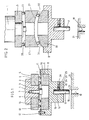
- the robot wrist includes an arm 1 which has a shoulder 2 and an end portion 3 of reduced diameter; the latter is engaged in the bore 4 of a flat disc 5 which is magnetized in the direction of the axis of the arm and of the disc, that is to say that its magnetized faces are its faces perpendicular to this axis.
- the disc is held against the shoulder 2 by a non-magnetic washer 6 fixed by screws 7.
- the robot wrist also includes a tip 8 having a bore 9 in which is disposed a magnetic disc 10, of the same shape and the same section as the disc 5. This disc is held in the bore 9 by a non-magnetic washer 11 fixed by screws 12 on the edge of the nozzle 8.
- the end piece 8 is arranged so that the two discs 5 and 10 are opposite; these discs are fixed so that their opposite faces have opposite polarities and thus tend to attract each other. They are kept separate from each other by metal balls 13 which are interposed between them allowing small displacements of the nozzle 8 parallel to itself relative to the arm 1.
- the washers 7 and 11 serve as buffers inside and outside for these balls and prevent them from escaping.
- the mutual attraction of the two discs 5 and 10 and the transmission of the magnetic flux by the balls 13 ensure self-centering of the end piece 8 relative to the arm 1 and a homogeneous distribution of the balls in the separation interval 14.
- the end piece 8 has, at its end opposite the disc 5, a reduced diameter portion 15 provided with an axial bore 16.
- this bore can be fitted a part 17, for example cylindrical, the end of which has a chamfer 18 and which is intended to be inserted in a bore 19, also provided with a chamfer 20, with a fixed part 21.
- the part 17 can be held in the endpiece by a ball or a support roller 22 on which a spring 23 can exert a thrust by means of a washer 24.
- the latter is integral with a pull rod axial 25 controlled by an electromagnet 26.
- the magnetization of the discs 5 and 10 is such that the attraction force is greater than the weight of the end piece 8 carrying the part 17.
- the transverse force exerted by the chamfer 18 causes a displacement of the end piece by rolling of the balls 13 against the opposite faces of the discs 5 and 10.
- the electromagnet 26 is actuated so that the support washer 24 moves away from the ball or the roller 22, the part no longer held in the bore 16.
- the transverse force exerted on the end piece disappears and this end piece automatically refocuses under the effect of the attraction of the two discs .
- FIG. 2 there is again the arm 1 on which the magnetic disc 5 is fixed. But opposite this is a magnetic part 27 which has a circular planar face 28 facing the disc 5, of the same cross section as this disc, the balls 13 being interposed between this flat face and the disc, and a concave spherical face 29.
- the wrist also comprises another magnetized part 30, fixed in the end piece 8 and having a spherical face convex 31 disposed opposite the spherical face 29 of the part 27, these two faces having the same cross section and having opposite polarities.
- the two faces 29 of the part have the same center located in the vicinity of the end of the part to be introduced 17.
- Metal balls 32 are interposed between the two faces 29 and 31. Washers similar to the washers 6 and 11 and not shown in the drawing prevent the balls 13 and 32 from escaping.
- the part 17 can thus move parallel to itself relative to the arm 1 in any direction while the end piece 8 can pivot in any direction relative to the part 27. It can thus be seen that it it is possible to correct a position defect according to two degrees of freedom and an orientation defect also according to two degrees of freedom.
Landscapes
- Engineering & Computer Science (AREA)
- Mechanical Engineering (AREA)
- Robotics (AREA)
- Manipulator (AREA)
Claims (8)
Applications Claiming Priority (2)
| Application Number | Priority Date | Filing Date | Title |
|---|---|---|---|
| FR8320978A FR2558404B1 (fr) | 1983-12-23 | 1983-12-23 | Poignet de robot magnetique |
| FR8320978 | 1983-12-23 |
Publications (2)
| Publication Number | Publication Date |
|---|---|
| EP0148677A1 EP0148677A1 (de) | 1985-07-17 |
| EP0148677B1 true EP0148677B1 (de) | 1989-03-22 |
Family
ID=9295678
Family Applications (1)
| Application Number | Title | Priority Date | Filing Date |
|---|---|---|---|
| EP84402575A Expired EP0148677B1 (de) | 1983-12-23 | 1984-12-13 | Magnetisches Roboterhandgelenk |
Country Status (4)
| Country | Link |
|---|---|
| US (1) | US4609325A (de) |
| EP (1) | EP0148677B1 (de) |
| DE (1) | DE3477354D1 (de) |
| FR (1) | FR2558404B1 (de) |
Families Citing this family (18)
| Publication number | Priority date | Publication date | Assignee | Title |
|---|---|---|---|---|
| DE8506071U1 (de) * | 1985-03-02 | 1985-05-23 | Sillner, Georg, 8411 Zeitlarn | Wendeeinrichtung für elektrische Radial-Bauelemente |
| US4778329A (en) * | 1986-03-21 | 1988-10-18 | General Motors Corporation | Robot with floating XY plane arm |
| JPH0453914Y2 (de) * | 1986-09-16 | 1992-12-17 | ||
| DE3641368A1 (de) * | 1986-12-03 | 1988-06-09 | Mannesmann Ag | Lagerung fuer einen greifer oder dergleichen |
| US4896431A (en) * | 1987-11-06 | 1990-01-30 | Canon Kabushiki Kaisha | Alignment apparatus |
| US4860864A (en) * | 1987-11-16 | 1989-08-29 | General Motors Corporation | Clutch for robot or like |
| US5020964A (en) * | 1989-11-27 | 1991-06-04 | Ford Motor Company | Method and apparatus for robotic transfer of workpieces |
| US5727717A (en) * | 1991-07-16 | 1998-03-17 | Vigne; Patrick | Magnetically coupled joints for mannequins and forms |
| US5180248A (en) * | 1991-08-05 | 1993-01-19 | Motorola, Inc. | Method and apparatus for correcting misalignments in couplings |
| US7144179B2 (en) * | 2000-01-26 | 2006-12-05 | Fusion Specialties, Inc. | Display form having magnetically attachable parts |
| DE60127241T2 (de) | 2000-01-26 | 2007-11-15 | Fusion Specialties, Inc., Broomfield | Manneqin mit magnetisch befestigbaren teilen |
| DE10244964B4 (de) * | 2002-09-26 | 2013-10-17 | Fraunhofer-Gesellschaft zur Förderung der angewandten Forschung e.V. | Vorrichtung und Verfahren zur automatischen Bestückung von Klemm-Magazinen mit Werkstücken |
| ES1054227Y (es) * | 2003-01-20 | 2003-10-16 | Simon Bernat Amadas | Autocentrador para acoplamiento entre dos cuerpos. |
| JP4286280B2 (ja) * | 2006-12-01 | 2009-06-24 | 株式会社ビーイング | ロボットハンドの過負荷安全装置 |
| CN100448628C (zh) * | 2007-06-20 | 2009-01-07 | 重庆大学 | 机械柔性空间对接平台 |
| DE102014102791A1 (de) * | 2014-03-03 | 2015-09-03 | Bayerische Motoren Werke Aktiengesellschaft | Vakuumgreifer |
| CN115319788A (zh) | 2017-03-06 | 2022-11-11 | 伯克希尔格雷运营股份有限公司 | 用于有效地移动各种物体的系统和方法 |
| WO2023141260A1 (en) | 2022-01-21 | 2023-07-27 | Berkshire Grey Operating Company, Inc. | Systems and methods for object processing with programmable motion devices using yawing grippers |
Family Cites Families (12)
| Publication number | Priority date | Publication date | Assignee | Title |
|---|---|---|---|---|
| US2678228A (en) * | 1951-06-08 | 1954-05-11 | Bausch & Lomb | Diagnostic instrument with magnetic connector |
| BE548557A (de) * | 1955-06-13 | Eckold Walter | ||
| US3079191A (en) * | 1960-02-12 | 1963-02-26 | Walker O S Co Inc | Permanent magnet lifting device |
| FR1504027A (fr) * | 1966-10-21 | 1967-12-01 | Materiel Electromagnetique S I | Dispositif magnétique de centrage |
| US4179783A (en) * | 1974-12-16 | 1979-12-25 | Hitachi, Ltd. | Holding apparatus with elastic mechanism |
| US4098001A (en) * | 1976-10-13 | 1978-07-04 | The Charles Stark Draper Laboratory, Inc. | Remote center compliance system |
| FR2445199A1 (fr) * | 1978-12-27 | 1980-07-25 | Jaz Sa | Poignet elastique monte a la partie terminale d'un organe de manipulation a distance d'objet |
| SE7900910L (sv) * | 1979-02-02 | 1980-08-03 | Christer Johansson | Maskinelement ii |
| SU872256A1 (ru) * | 1980-01-14 | 1981-10-15 | Предприятие П/Я Р-6930 | Кисть промышленного робота |
| DE3003990C2 (de) * | 1980-02-04 | 1982-08-12 | Jungheinrich Unternehmensverwaltung Kg, 2000 Hamburg | Sicherheitseinrichtung zwischen einem Haltearm und einem Werkzeugträger eines Handhabungsgerätes |
| US4337579A (en) * | 1980-04-16 | 1982-07-06 | The Charles Stark Draper Laboratory, Inc. | Deformable remote center compliance device |
| CH644291A5 (en) * | 1981-05-15 | 1984-07-31 | Microbo Sa | Orientation device with a centre of rotation outside a machine (assembly) tool |
-
1983
- 1983-12-23 FR FR8320978A patent/FR2558404B1/fr not_active Expired
-
1984
- 1984-12-13 DE DE8484402575T patent/DE3477354D1/de not_active Expired
- 1984-12-13 EP EP84402575A patent/EP0148677B1/de not_active Expired
- 1984-12-21 US US06/684,905 patent/US4609325A/en not_active Expired - Fee Related
Also Published As
| Publication number | Publication date |
|---|---|
| FR2558404A1 (fr) | 1985-07-26 |
| DE3477354D1 (en) | 1989-04-27 |
| EP0148677A1 (de) | 1985-07-17 |
| FR2558404B1 (fr) | 1986-12-19 |
| US4609325A (en) | 1986-09-02 |
Similar Documents
| Publication | Publication Date | Title |
|---|---|---|
| EP0148677A1 (de) | Magnetisches Roboterhandgelenk | |
| EP0030165B1 (de) | Selbstzentrierendes Kupplungsausrücklager | |
| EP0163558B1 (de) | Vorrichtung zum Montieren von Ventilen in Verbrennungskraftmaschinen | |
| CH489864A (de) | Mehrspur-Magnetkopf | |
| EP0070766B1 (de) | Gelenkbolzen zur Verbindung zweier Teile | |
| EP2927785A1 (de) | Bremse für einen trackball | |
| CH711220A2 (fr) | Dispositif magnétique de pivotement d'un arbre dans un mouvement horloger. | |
| FR2540950A1 (fr) | Dispositif de debrayage du type auto-centreur | |
| FR2635151A1 (fr) | Assemblage et procede pour empecher une piece de se deplacer le long d'un arbre | |
| FR2728378B1 (fr) | Dispositif de mise en rotation pour la lecture d'un disque optique | |
| FR2681918A1 (fr) | Dispositif pour l'assemblage et le desassemblage rapide de deux pieces l'une sur l'autre. | |
| EP0336802A1 (de) | Rolle, inbesondere für Gepäck | |
| EP0301071B1 (de) | Fernmanipulierbares ventil | |
| US2681501A (en) | Device for removing articles from their supports | |
| FR2527965A1 (fr) | Dispositif de guidage en translation | |
| FR2476407A1 (fr) | Dispositif de centrage d'un rotor | |
| EP0593338B1 (de) | Einrichtung zur Zusammensetzung von zwei Teilen in einer Verschraubungsstation | |
| FR2513711A1 (fr) | Dispositif de liaison entre un arbre et un volant | |
| FR2527828A1 (fr) | Dispositif pour arreter la transmission des phenomenes seismiques | |
| FR2689581A1 (fr) | Chapeau de métal auto-bloquant et palier en plastique. | |
| EP3179314A1 (de) | Spiralklötzchenträger mit vereinfachter montage | |
| EP0307327B1 (de) | Schraubverbindungensvorrichtung für zwei Elemente mit der Möglichkeit den Abstand dazwischen einzustellen | |
| FR2823274A1 (fr) | Palier pour organe mecanique de transmission a roulement | |
| EP3964884A1 (de) | Befestigungsvorrichtung für eine brillenfassung | |
| EP0045248B1 (de) | Stoss- und/oder schwingungsdämpfendes Lager |
Legal Events
| Date | Code | Title | Description |
|---|---|---|---|
| PUAI | Public reference made under article 153(3) epc to a published international application that has entered the european phase |
Free format text: ORIGINAL CODE: 0009012 |
|
| AK | Designated contracting states |
Designated state(s): DE GB IT |
|
| 17P | Request for examination filed |
Effective date: 19851128 |
|
| 17Q | First examination report despatched |
Effective date: 19870401 |
|
| GRAA | (expected) grant |
Free format text: ORIGINAL CODE: 0009210 |
|
| AK | Designated contracting states |
Kind code of ref document: B1 Designated state(s): DE GB IT |
|
| ITF | It: translation for a ep patent filed | ||
| GBT | Gb: translation of ep patent filed (gb section 77(6)(a)/1977) | ||
| REF | Corresponds to: |
Ref document number: 3477354 Country of ref document: DE Date of ref document: 19890427 |
|
| REG | Reference to a national code |
Ref country code: GB Ref legal event code: 746 |
|
| ITPR | It: changes in ownership of a european patent |
Owner name: OFFERTA DI LICENZA AL PUBBLICO |
|
| PLBE | No opposition filed within time limit |
Free format text: ORIGINAL CODE: 0009261 |
|
| STAA | Information on the status of an ep patent application or granted ep patent |
Free format text: STATUS: NO OPPOSITION FILED WITHIN TIME LIMIT |
|
| 26N | No opposition filed | ||
| ITTA | It: last paid annual fee | ||
| PGFP | Annual fee paid to national office [announced via postgrant information from national office to epo] |
Ref country code: GB Payment date: 19971205 Year of fee payment: 14 |
|
| PGFP | Annual fee paid to national office [announced via postgrant information from national office to epo] |
Ref country code: DE Payment date: 19971222 Year of fee payment: 14 |
|
| PG25 | Lapsed in a contracting state [announced via postgrant information from national office to epo] |
Ref country code: GB Free format text: LAPSE BECAUSE OF NON-PAYMENT OF DUE FEES Effective date: 19981213 |
|
| GBPC | Gb: european patent ceased through non-payment of renewal fee |
Effective date: 19981213 |
|
| PG25 | Lapsed in a contracting state [announced via postgrant information from national office to epo] |
Ref country code: DE Free format text: LAPSE BECAUSE OF NON-PAYMENT OF DUE FEES Effective date: 19991001 |