EP0149860A1 - Druckfixiereinrichtung - Google Patents
Druckfixiereinrichtung Download PDFInfo
- Publication number
- EP0149860A1 EP0149860A1 EP84201665A EP84201665A EP0149860A1 EP 0149860 A1 EP0149860 A1 EP 0149860A1 EP 84201665 A EP84201665 A EP 84201665A EP 84201665 A EP84201665 A EP 84201665A EP 0149860 A1 EP0149860 A1 EP 0149860A1
- Authority
- EP
- European Patent Office
- Prior art keywords
- contact
- contact fixing
- roller
- cleaning roller
- toner
- Prior art date
- Legal status (The legal status is an assumption and is not a legal conclusion. Google has not performed a legal analysis and makes no representation as to the accuracy of the status listed.)
- Granted
Links
- 238000004140 cleaning Methods 0.000 claims abstract description 56
- 239000000463 material Substances 0.000 claims abstract description 11
- 238000010438 heat treatment Methods 0.000 claims abstract description 8
- 239000000155 melt Substances 0.000 claims description 4
- 229920002379 silicone rubber Polymers 0.000 description 7
- 239000004945 silicone rubber Substances 0.000 description 7
- 239000000428 dust Substances 0.000 description 3
- 229910052751 metal Inorganic materials 0.000 description 3
- 239000002184 metal Substances 0.000 description 3
- 230000004087 circulation Effects 0.000 description 2
- 230000000694 effects Effects 0.000 description 2
- 229910000831 Steel Inorganic materials 0.000 description 1
- 239000004411 aluminium Substances 0.000 description 1
- 229910052782 aluminium Inorganic materials 0.000 description 1
- XAGFODPZIPBFFR-UHFFFAOYSA-N aluminium Chemical compound [Al] XAGFODPZIPBFFR-UHFFFAOYSA-N 0.000 description 1
- 230000015572 biosynthetic process Effects 0.000 description 1
- 238000010073 coating (rubber) Methods 0.000 description 1
- 150000002739 metals Chemical class 0.000 description 1
- 239000004033 plastic Substances 0.000 description 1
- 229920003023 plastic Polymers 0.000 description 1
- 239000010959 steel Substances 0.000 description 1
- -1 steel or aluminium Chemical class 0.000 description 1
Images
Classifications
-
- G—PHYSICS
- G03—PHOTOGRAPHY; CINEMATOGRAPHY; ANALOGOUS TECHNIQUES USING WAVES OTHER THAN OPTICAL WAVES; ELECTROGRAPHY; HOLOGRAPHY
- G03G—ELECTROGRAPHY; ELECTROPHOTOGRAPHY; MAGNETOGRAPHY
- G03G15/00—Apparatus for electrographic processes using a charge pattern
- G03G15/20—Apparatus for electrographic processes using a charge pattern for fixing, e.g. by using heat
- G03G15/2003—Apparatus for electrographic processes using a charge pattern for fixing, e.g. by using heat using heat
- G03G15/2014—Apparatus for electrographic processes using a charge pattern for fixing, e.g. by using heat using heat using contact heat
- G03G15/2017—Structural details of the fixing unit in general, e.g. cooling means, heat shielding means
- G03G15/2025—Structural details of the fixing unit in general, e.g. cooling means, heat shielding means with special means for lubricating and/or cleaning the fixing unit, e.g. applying offset preventing fluid
-
- G—PHYSICS
- G03—PHOTOGRAPHY; CINEMATOGRAPHY; ANALOGOUS TECHNIQUES USING WAVES OTHER THAN OPTICAL WAVES; ELECTROGRAPHY; HOLOGRAPHY
- G03G—ELECTROGRAPHY; ELECTROPHOTOGRAPHY; MAGNETOGRAPHY
- G03G2215/00—Apparatus for electrophotographic processes
- G03G2215/16—Transferring device, details
- G03G2215/1647—Cleaning of transfer member
- G03G2215/1657—Cleaning of transfer member of transfer drum
-
- G—PHYSICS
- G03—PHOTOGRAPHY; CINEMATOGRAPHY; ANALOGOUS TECHNIQUES USING WAVES OTHER THAN OPTICAL WAVES; ELECTROGRAPHY; HOLOGRAPHY
- G03G—ELECTROGRAPHY; ELECTROPHOTOGRAPHY; MAGNETOGRAPHY
- G03G2215/00—Apparatus for electrophotographic processes
- G03G2215/16—Transferring device, details
- G03G2215/1676—Simultaneous toner image transfer and fixing
- G03G2215/1695—Simultaneous toner image transfer and fixing at the second or higher order transfer point
Definitions
- This invention relates to a contact fixing device for fixing a toner image on a sheet material, comprising:
- a contact fixing device of this kind is known from US Patent 3649992.
- paper dust and toner adhering thereto, remaining on the contact fixing medium are removed by bringing the latter into contact with a metal roller to which the toner adheres more satisfactorily.
- a metal roller of this kind has the disadvantage that an uneven layer of toner gradually builds up on it, so that shallow parts close to high parts no longer exert any cleaning effect because the contact between the contact fixing medium and these shallow parts is inadequate. Also, the toner layer becomes too thick and ribs form parallel to the axis of the cleaning roller in the built-up toner layer as the contact device cools after being stopped in the heated condition.
- the object of the invention is to provide a contact fixing device of the kind indicated without the said disadvantages.
- the cleaning surface of the cleaning roller is provided with perforations which communicate with a cavity in the roller.
- the presence of the perforations causes surplus toner to be discharged to the interior of the roller thus on the one hand reducing unevenness and on the other hand ensuring that only a thin layer of toner is left on the roller.
- the axis of the cleaning roller is inclined to the direction of movement of the contact fixing medium. This promotes the formation of a thin uniform layer of toner since a transverse conveyance of toner forms so that the toner is conveyed to the perforations more rapidly.
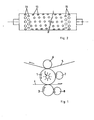
- the contact fixing device illustrated in Fig. 1 comprises a contact fixing roller 1 coated with a layer of silicone rubber and rotatable in the direction of the arrow.
- Contact fixing roller 1 is heated by a heating element 2 disposed in the roller.
- a pressure roller 3 also coated with silicone rubber is pressed against the contact fixing roller.
- a copy sheet 4 is fed between the contact fixing roller 1 and the pressure roller 3 by conveyor means (not shown).
- a photoconductive belt 5 is brought into contact with the contact fixing roller by means of a roller 6 on the side remote from the pressure roller 3.
- a toner image applied to the photoconductive belt is transferred to the roller 1 in the nip between the belt 5 and the contact fixing roller 1, is softened on this roller and conveyed to the nip between roller 1 and the pressure roller 3. In the latter nip the softened toner image is transferred to the copy sheet 4 and then fixed thereon.
- a cooperating cleaning roller 7 is pressed against the roller 1 and a cooperating cleaning roller 8 is pressed against the pressure roller 3.
- Cleaning roller 7 is so disposed that its axis of rotation includes an angle with the direction of movement of the contact fixing roller 1 in the plane of contact with the cleaning roller.
- the degree of inclination of the cleaning roller is not critical.
- the transverse conveyance of toner increases with the degree of inclination, but generally an angle of 89.7° to the direction of advance of the contact fixing medium in the plane of contact with the cleaning roller is more than adequate.
- this angle corresponds to a 2 mm deviation from the position perpendicular to the said direction of movement.
- An angle of 89.9° already gives a clear effect and an angle less than 89.3° is generally unnecessary. It must be noted in this connection that the minimum adjustable angle is restricted in cases in which a contact fixing medium is used in the form of a roller.
- the axis of rotation of the cleaning roller 8 includes an angle with the direction of movement of the pressure roller 3 in the plane of contact with the cleaning roller 8.
- the cleaning rollers 7 and 8 are hollow and the cleaning portion coming into contact with the silicone rubber layer of the contact fixing roller or pressure roller is perforated in both rollers 7 and 8 as indicated in Fig. 2 in respect of one of the rollers 7,8 which are identical.
- Two rows of perforations 11 with a diameter of 3 mm are disposed near each edge of the cleaning rollers and around the cylindrical surface thereof. These perforations, which are situated outside the cleaning surface of the rollers, receive all the toner conveyed to the edge, in order to prevent toner from dropping over the edge of the cleaning rollers and moving uncontrollably.
- perforations 12 are disposed along a double helix.
- the diameter of these perforations is not critical, but an optimum diameter can be indicated.
- the rate of discharge of the toner depends on the viscosity of the toner at the processing temperature, the optimum diameter of the perforations should be determined experimentally for each case. It is generally between 1 and 2 mm.
- the centre-to-centre distance of the perforations is not critical either. On the one hand a large cleaning surface without perforations is desirable while on the other hand the toner must be able to reach a perforation sufficiently quickly. Since the speed depends on the toner viscosity, the optimum centre-to-centre distance is determined by the toner viscosity and must be determined experimentally for each situation. In most cases the centre-to-centre distance is between 4 and 6 mm.
- the cleaning roller has no cleaning action at the perforations, that does not cause any problems, since after a number of circulations each part of the silicone rubber surface has come into contact with a part of the cleaning roller containing no perforation. Even if the circumference of the contact fixing medium is equal to that of the cleaning roller, these two elements appear to rotate sufficiently asynchronously to ensure that a perforation will not come into contact twice with exactly the same spot on the contact fixing medium during two consecutive circulations. In order, however, to load the silicone rubber as uniformly as possible with the cleaning roller and in order to keep the toner layer on the cleaning roller at a uniform thickness as far as possible, it is desirable to ensure that each part of the silicone rubber surface comes into contact with a perforation equally frequently.
- the perforations are therefore preferably disposed along a helix in the cleaning surface of the cleaning roller.
- the action of the cleaning roller can be further improved in this respect by developing a photoconductive strip from time to time in a copier, the said strip having a surface of the same dimensions as the cleaning surface of the cleaning roller,and by conveying the toner layer through the contact fixing device without supplying a sheet material. In this way the cleaning roller is provided with a layer of fresh toner which readily picks up paper dust.
- the most suitable materials for the cleaning roller are metals, such as steel or aluminium, but the cleaning roller may consist of plastics to the extent permissible by the operating temperature. If the cleaning roller is not kept sufficiently at temperature by the heating elements for the toner image, this roller can be heated separately, for example by means of a heating element incorporated in the roller.
- the above-described embodiment relates to a contact fixing device in which the contact fixing medium also function as an intermediate medium for the image to be fixed
- the invention naturally also relates to contact fixing devices in which the contact fixing medium is used exclusively to fix an image previously applied to a receiving material.
Landscapes
- Physics & Mathematics (AREA)
- General Physics & Mathematics (AREA)
- Fixing For Electrophotography (AREA)
Applications Claiming Priority (2)
| Application Number | Priority Date | Filing Date | Title |
|---|---|---|---|
| NL8304099A NL8304099A (nl) | 1983-11-30 | 1983-11-30 | Contactfixeerinrichting. |
| NL8304099 | 1983-11-30 |
Publications (2)
| Publication Number | Publication Date |
|---|---|
| EP0149860A1 true EP0149860A1 (de) | 1985-07-31 |
| EP0149860B1 EP0149860B1 (de) | 1988-03-02 |
Family
ID=19842787
Family Applications (1)
| Application Number | Title | Priority Date | Filing Date |
|---|---|---|---|
| EP84201665A Expired EP0149860B1 (de) | 1983-11-30 | 1984-11-19 | Druckfixiereinrichtung |
Country Status (8)
| Country | Link |
|---|---|
| US (1) | US4607947A (de) |
| EP (1) | EP0149860B1 (de) |
| JP (1) | JPS60138581A (de) |
| AU (1) | AU561522B2 (de) |
| CA (1) | CA1223032A (de) |
| DE (1) | DE3469612D1 (de) |
| NL (1) | NL8304099A (de) |
| ZA (1) | ZA848084B (de) |
Cited By (3)
| Publication number | Priority date | Publication date | Assignee | Title |
|---|---|---|---|---|
| EP0318078A1 (de) * | 1987-11-11 | 1989-05-31 | Océ-Nederland B.V. | Vorrichtung zum Übertragen eines pulverförmigen Bildes auf ein Empfangsmaterial und zum Fixieren dieses pulverförmigen Bildes auf diesem Material |
| NL1003092C2 (nl) * | 1996-05-13 | 1997-11-18 | Oce Tech Bv | Reinigingsorgaan voor het reinigen van onder andere het fixeeroppervlak van een thermische contactfixeerinrichting. |
| US6360073B1 (en) | 1999-10-30 | 2002-03-19 | Xeikon Nv | Apparatus and method for fixing toner images onto a recording medium |
Families Citing this family (40)
| Publication number | Priority date | Publication date | Assignee | Title |
|---|---|---|---|---|
| NL8501321A (nl) * | 1985-05-09 | 1986-12-01 | Oce Nederland B V Patents And | Werkwijze voor het bepalen van het moment waarop verversing van een laag klevend materiaal op een reinigingsorgaan noodzakelijk is, en inrichting voor het uitvoeren van deze werkwijze. |
| NL8501718A (nl) * | 1985-06-14 | 1987-01-02 | Oce Nederland B V Patents And | Contactfixeerinrichting. |
| US5081502A (en) * | 1987-07-15 | 1992-01-14 | Hitachi, Ltd. | Radiant heat fixing apparatus |
| US4903082A (en) * | 1988-05-10 | 1990-02-20 | Xerox Corporation | Liquid ink fusing and drying system |
| NL9101395A (nl) * | 1991-08-16 | 1993-03-16 | Oce Nederland Bv | Inrichting voor het overdragen van een tonerbeeld van een beeldvormingsmedium naar een ontvangstmateriaal. |
| US5284524A (en) * | 1991-10-03 | 1994-02-08 | Rockwell International Corporation | Method and apparatus for enhancing surface treatment of perforated materials |
| US5332642A (en) * | 1991-10-18 | 1994-07-26 | Xerox Corporation | Vacuum assisted dispersant reduction system |
| NL9201347A (nl) * | 1992-07-27 | 1994-02-16 | Oce Nederland Bv | Inrichting voor het overdragen van een tonerbeeld van een beeldvormingsmedium naar een ontvangstmateriaal. |
| NL9201348A (nl) * | 1992-07-27 | 1994-02-16 | Oce Nederland Bv | Inrichting voor het overdragen van een tonerbeeld van een beeldvormingsmedium naar een ontvangstmateriaal. |
| NL9400382A (nl) * | 1994-03-11 | 1995-10-02 | Oce Nederland Bv | Inrichting voor het overdragen van een tonerbeeld van een beeldvormingsmedium naar een ontvangstmateriaal. |
| US5424813A (en) * | 1994-05-23 | 1995-06-13 | Xerox Corporation | Apparatus and method for improved blotter roller permeability |
| JP2970514B2 (ja) * | 1995-04-28 | 1999-11-02 | 富士ゼロックス株式会社 | 余剰現像液除去装置 |
| DE69609288T2 (de) * | 1995-10-23 | 2001-01-18 | Oce-Technologies B.V., Venlo | Gerät zum Übertragen eines Tonerbildes von einem Bildaufzeichnungsträger zu einem Empfangsträger |
| NL1001471C2 (nl) * | 1995-10-23 | 1997-04-25 | Oce Nederland Bv | Inrichting voor het overdragen van een tonerbeeld van een beeldvormings- medium naar een ontvangstmateriaal. |
| DE19607037C2 (de) * | 1996-02-24 | 1999-03-25 | Roland Man Druckmasch | Verfahren zum Reinigen einer Druckmaschinenzylinderoberfläche mit einer Oberflächenstruktur |
| WO1998025188A1 (en) * | 1996-12-03 | 1998-06-11 | Indigo N.V. | Method and apparatus for cleaning an image transfer member |
| JPH10240047A (ja) * | 1997-02-21 | 1998-09-11 | Canon Inc | 画像形成装置 |
| KR100322563B1 (ko) * | 1998-03-20 | 2002-06-26 | 윤종용 | 습식인쇄기의크리닝장치 |
| US6078776A (en) * | 1998-04-30 | 2000-06-20 | Nec Corporation | Image formation apparatus having a peeling claw and heated rollers |
| US6089703A (en) * | 1998-10-27 | 2000-07-18 | Lexmark International, Inc. | Ink jet printer and method of printing using same |
| US6507393B2 (en) * | 1999-05-12 | 2003-01-14 | John Samuel Batchelder | Surface cleaning and particle counting |
| US6215975B1 (en) * | 1999-07-26 | 2001-04-10 | Xerox Corporation | Cleaning apparatus for a fusing member |
| US6223016B1 (en) * | 1999-12-16 | 2001-04-24 | Xerox Corporation | Cleaning apparatus for a fusing member |
| US6487389B2 (en) | 2000-11-30 | 2002-11-26 | Xerox Corporation | Refreshing a sticky cleaner for a fuser |
| US7303273B2 (en) * | 2002-01-31 | 2007-12-04 | Hewlett-Packard Development Company, L.P. | Heated roll system for drying printed media |
| US6679599B2 (en) * | 2002-01-31 | 2004-01-20 | Hewlett-Packard Development Company, L.P. | Heated roll system for drying printed media |
| JP4044060B2 (ja) * | 2003-12-09 | 2008-02-06 | シャープ株式会社 | 定着装置のクリーニング装置 |
| EP1564604B1 (de) * | 2004-02-16 | 2013-06-19 | Ricoh Company, Ltd. | Fixiergerät mit Reinigungselement und Bilderzeugungsgerät |
| JP4979910B2 (ja) * | 2004-09-01 | 2012-07-18 | オセ−テクノロジーズ・ベー・ヴエー | 画像転写装置およびその一部をクリーニングするための方法 |
| EP1632821B1 (de) * | 2004-09-01 | 2012-05-30 | Océ-Technologies B.V. | Zwischenübertragungselement mit einem Reinigungselement |
| JP2006143471A (ja) * | 2004-10-18 | 2006-06-08 | Hokushin Ind Inc | 給紙ロール |
| JP4219358B2 (ja) * | 2005-08-31 | 2009-02-04 | シャープ株式会社 | クリーニング部材及びこれを用いた画像形成装置 |
| US7512368B2 (en) * | 2006-10-27 | 2009-03-31 | Xerox Corporation | Cleaning systems for fuser members and method of cleaning fuser members |
| US7869752B2 (en) * | 2007-06-23 | 2011-01-11 | Ricoh Company Limited | Cleaning device, fixing device, and image forming apparatus |
| ATE488785T1 (de) | 2007-10-02 | 2010-12-15 | Oce Tech Bv | Vorrichtung und verfahren zur riemenlenkung |
| JP5396050B2 (ja) * | 2007-10-02 | 2014-01-22 | オセ−テクノロジーズ ビーブイ | ベルトを操縦するための装置及び方法 |
| US8483590B2 (en) * | 2010-10-08 | 2013-07-09 | Xerox Corporation | Method and apparatus for external heater roll cleaning |
| US9027540B2 (en) | 2011-01-28 | 2015-05-12 | Copper John Corporation | Bowstring release |
| USD688346S1 (en) | 2011-08-12 | 2013-08-20 | Scott Archery Manufacturing | Archery release |
| US10145646B2 (en) | 2014-11-13 | 2018-12-04 | Scott Archery Llc | Archery bowstring release enabling sensitivity adjustment |
Citations (3)
| Publication number | Priority date | Publication date | Assignee | Title |
|---|---|---|---|---|
| US3976814A (en) * | 1974-08-14 | 1976-08-24 | Xerox Corporation | Fusing method |
| US4086871A (en) * | 1977-05-18 | 1978-05-02 | Minnesota Mining And Manufacturing Company | Lubricator roll |
| US4411042A (en) * | 1980-12-25 | 1983-10-25 | Minolta Camera Kabushiki Kaisha | Cleaning device |
Family Cites Families (4)
| Publication number | Priority date | Publication date | Assignee | Title |
|---|---|---|---|---|
| US3649992A (en) * | 1969-12-30 | 1972-03-21 | Xerox Corp | Cleaning apparatus for fusing system |
| US3706491A (en) * | 1971-12-16 | 1972-12-19 | Ibm | Fuser roll cleaning method and apparatus for performing it |
| US3781107A (en) * | 1972-08-09 | 1973-12-25 | Xerox Corp | Cleaning apparatus |
| US4324482A (en) * | 1980-11-28 | 1982-04-13 | Xerox Corporation | Pressure roll cleaning device |
-
1983
- 1983-11-30 NL NL8304099A patent/NL8304099A/nl unknown
-
1984
- 1984-10-17 ZA ZA848084A patent/ZA848084B/xx unknown
- 1984-10-23 AU AU34585/84A patent/AU561522B2/en not_active Ceased
- 1984-11-16 US US06/671,953 patent/US4607947A/en not_active Expired - Lifetime
- 1984-11-19 DE DE8484201665T patent/DE3469612D1/de not_active Expired
- 1984-11-19 EP EP84201665A patent/EP0149860B1/de not_active Expired
- 1984-11-21 JP JP59246955A patent/JPS60138581A/ja active Granted
- 1984-11-23 CA CA000468575A patent/CA1223032A/en not_active Expired
Patent Citations (3)
| Publication number | Priority date | Publication date | Assignee | Title |
|---|---|---|---|---|
| US3976814A (en) * | 1974-08-14 | 1976-08-24 | Xerox Corporation | Fusing method |
| US4086871A (en) * | 1977-05-18 | 1978-05-02 | Minnesota Mining And Manufacturing Company | Lubricator roll |
| US4411042A (en) * | 1980-12-25 | 1983-10-25 | Minolta Camera Kabushiki Kaisha | Cleaning device |
Cited By (5)
| Publication number | Priority date | Publication date | Assignee | Title |
|---|---|---|---|---|
| EP0318078A1 (de) * | 1987-11-11 | 1989-05-31 | Océ-Nederland B.V. | Vorrichtung zum Übertragen eines pulverförmigen Bildes auf ein Empfangsmaterial und zum Fixieren dieses pulverförmigen Bildes auf diesem Material |
| NL1003092C2 (nl) * | 1996-05-13 | 1997-11-18 | Oce Tech Bv | Reinigingsorgaan voor het reinigen van onder andere het fixeeroppervlak van een thermische contactfixeerinrichting. |
| EP0807871A1 (de) * | 1996-05-13 | 1997-11-19 | Océ-Technologies B.V. | Reinigungseinrichtung zur Reinigung von beispielsweise einer Fixieroberfläche eines thermischen Kontaktfixiergerätes |
| US5768672A (en) * | 1996-05-13 | 1998-06-16 | Oce-Technologies B.V. | Cleaning members of image recording devices |
| US6360073B1 (en) | 1999-10-30 | 2002-03-19 | Xeikon Nv | Apparatus and method for fixing toner images onto a recording medium |
Also Published As
| Publication number | Publication date |
|---|---|
| US4607947A (en) | 1986-08-26 |
| EP0149860B1 (de) | 1988-03-02 |
| AU3458584A (en) | 1985-06-06 |
| NL8304099A (nl) | 1985-06-17 |
| CA1223032A (en) | 1987-06-16 |
| DE3469612D1 (en) | 1988-04-07 |
| AU561522B2 (en) | 1987-05-07 |
| ZA848084B (en) | 1985-10-30 |
| JPS60138581A (ja) | 1985-07-23 |
| JPH0431394B2 (de) | 1992-05-26 |
Similar Documents
| Publication | Publication Date | Title |
|---|---|---|
| EP0149860B1 (de) | Druckfixiereinrichtung | |
| US5708949A (en) | Image fixing device for image forming apparatus | |
| US4165965A (en) | Backup roll cleaning system for a heated roll fuser | |
| EP0485123B1 (de) | Vorrichtung zur Beseitigung von Blattwellungen | |
| EP0108615B1 (de) | Thermokopiergerät für Filme und Papiere | |
| US4050886A (en) | Roll fuser | |
| JPH0216918B2 (de) | ||
| US4937631A (en) | Fusing unit for a copy machine | |
| US5422710A (en) | Sheet discharging device for use in an image forming apparatus | |
| US4092099A (en) | Copier paper delivery means in a heat-fixing device of a copying machine | |
| EP0345034B1 (de) | Fixiergerät für ein Tonerbild in einer Bilderzeugungsmaschine | |
| US5394227A (en) | Compliant hard fusing pressure roller for reducing media curl and wave in electrophotographic printers | |
| US4693585A (en) | Contact fixing device with an improved cleaning roller | |
| US5659868A (en) | Pressure roll having a flat shaft for use in a heat and pressure fuser apparatus | |
| JPH0721686B2 (ja) | クリーニングブレード及びこのクリーニングブレードを用いた画像形成装置 | |
| JPH05197305A (ja) | 定着装置 | |
| JP2592937B2 (ja) | 定着装置 | |
| JPH0624845Y2 (ja) | 湿式電子写真製版機の定着装置 | |
| JPH01167165A (ja) | シート材搬送装置 | |
| JP2918233B2 (ja) | 定着装置 | |
| JP2000267525A (ja) | 画像形成材料除去装置 | |
| JPH0442283A (ja) | 定着記録紙の波状変形防止構造 | |
| JPH0348846A (ja) | 顕色剤塗布装置 | |
| EP0797131A1 (de) | Behandlung der Innenfläche eines Schmelzfixierwalzekernes | |
| JPH0314351B2 (de) |
Legal Events
| Date | Code | Title | Description |
|---|---|---|---|
| PUAI | Public reference made under article 153(3) epc to a published international application that has entered the european phase |
Free format text: ORIGINAL CODE: 0009012 |
|
| AK | Designated contracting states |
Designated state(s): DE FR GB NL |
|
| 17P | Request for examination filed |
Effective date: 19851220 |
|
| 17Q | First examination report despatched |
Effective date: 19870519 |
|
| GRAA | (expected) grant |
Free format text: ORIGINAL CODE: 0009210 |
|
| AK | Designated contracting states |
Kind code of ref document: B1 Designated state(s): DE FR GB NL |
|
| REF | Corresponds to: |
Ref document number: 3469612 Country of ref document: DE Date of ref document: 19880407 |
|
| ET | Fr: translation filed | ||
| PLBE | No opposition filed within time limit |
Free format text: ORIGINAL CODE: 0009261 |
|
| STAA | Information on the status of an ep patent application or granted ep patent |
Free format text: STATUS: NO OPPOSITION FILED WITHIN TIME LIMIT |
|
| 26N | No opposition filed | ||
| NLT1 | Nl: modifications of names registered in virtue of documents presented to the patent office pursuant to art. 16 a, paragraph 1 |
Owner name: OCE-TECHNOLOGIES B.V. |
|
| REG | Reference to a national code |
Ref country code: GB Ref legal event code: IF02 |
|
| PGFP | Annual fee paid to national office [announced via postgrant information from national office to epo] |
Ref country code: FR Payment date: 20021010 Year of fee payment: 19 |
|
| PGFP | Annual fee paid to national office [announced via postgrant information from national office to epo] |
Ref country code: GB Payment date: 20021016 Year of fee payment: 19 |
|
| PGFP | Annual fee paid to national office [announced via postgrant information from national office to epo] |
Ref country code: DE Payment date: 20021022 Year of fee payment: 19 |
|
| PGFP | Annual fee paid to national office [announced via postgrant information from national office to epo] |
Ref country code: NL Payment date: 20021130 Year of fee payment: 19 |
|
| PG25 | Lapsed in a contracting state [announced via postgrant information from national office to epo] |
Ref country code: GB Free format text: LAPSE BECAUSE OF NON-PAYMENT OF DUE FEES Effective date: 20031119 |
|
| PG25 | Lapsed in a contracting state [announced via postgrant information from national office to epo] |
Ref country code: NL Free format text: LAPSE BECAUSE OF NON-PAYMENT OF DUE FEES Effective date: 20040601 |
|
| PG25 | Lapsed in a contracting state [announced via postgrant information from national office to epo] |
Ref country code: DE Free format text: LAPSE BECAUSE OF NON-PAYMENT OF DUE FEES Effective date: 20040602 |
|
| GBPC | Gb: european patent ceased through non-payment of renewal fee |
Effective date: 20031119 |
|
| PG25 | Lapsed in a contracting state [announced via postgrant information from national office to epo] |
Ref country code: FR Free format text: LAPSE BECAUSE OF NON-PAYMENT OF DUE FEES Effective date: 20040730 |
|
| NLV4 | Nl: lapsed or anulled due to non-payment of the annual fee |
Effective date: 20040601 |
|
| REG | Reference to a national code |
Ref country code: FR Ref legal event code: ST |