EP0152484A1 - Dispositif d'entree et de sortie de donnees - Google Patents
Dispositif d'entree et de sortie de donnees Download PDFInfo
- Publication number
- EP0152484A1 EP0152484A1 EP83903221A EP83903221A EP0152484A1 EP 0152484 A1 EP0152484 A1 EP 0152484A1 EP 83903221 A EP83903221 A EP 83903221A EP 83903221 A EP83903221 A EP 83903221A EP 0152484 A1 EP0152484 A1 EP 0152484A1
- Authority
- EP
- European Patent Office
- Prior art keywords
- parity
- data
- tape
- puncher
- code
- Prior art date
- Legal status (The legal status is an assumption and is not a legal conclusion. Google has not performed a legal analysis and makes no representation as to the accuracy of the status listed.)
- Withdrawn
Links
Images


Classifications
-
- G—PHYSICS
- G06—COMPUTING OR CALCULATING; COUNTING
- G06K—GRAPHICAL DATA READING; PRESENTATION OF DATA; RECORD CARRIERS; HANDLING RECORD CARRIERS
- G06K5/00—Methods or arrangements for verifying the correctness of markings on a record carrier; Column detection devices
-
- G—PHYSICS
- G06—COMPUTING OR CALCULATING; COUNTING
- G06K—GRAPHICAL DATA READING; PRESENTATION OF DATA; RECORD CARRIERS; HANDLING RECORD CARRIERS
- G06K1/00—Methods or arrangements for marking the record carrier in digital fashion
- G06K1/02—Methods or arrangements for marking the record carrier in digital fashion by punching
Definitions
- This invention relates to a transportable data input/output unit capable of being detached from the body of a numerical control device.
- a host computer In numerical control, there are cases where a host computer is used and made to perform a variety of data processing to create command data for the machining of a workpiece.
- the data created by the host computer is recorded on a paper tape by a tape puncher and, with the paper tape serving as the recording medium, is used as input information for another system.
- the contents of the tape are printed out by a printer in order to provide a record thereof beforehand.
- the paper tape puncher and printer used ordinarily are provided separately of the host computer body. These pieces of equipment are connected to the host computer and operate solely in response to commands therefrom.
- the object of the present invention is to provide a data input/output unit of a numerical control device in a numerical control system, wherein the input/output unit is detachable from a host computer and includes a tape puncher, tape reader and printer combined into one, and wherein the operation of removing parity from data provided with parity, or of adding parity to data devoid of such parity, is capable of being performed by the data input/output unit itself or based on a command from a host computer.
- the present invention provides a processing function which not only enables a data input/output unit to operate in accordance with a command from a host computer in order to create a paper tape, print out transferred data and enter data, but which also enables the unit itself to be programmed independently to create a paper tape and print the data borne by the paper tape.
- a tape puncher is provided with a counter for counting the number of print characters in one block, a parity designating circuit for determining a parity change indicated by the value counted by the counter, and a puncher control circuit capable of adding or erasing a parity code.
- the puncher control circuit performs at least an addition or erasure of a parity code.
- the operation of removing parity from data provided with parity, or of adding parity to data devoid of such parity is capable of being performed by the data input/output unit itself or based on a command from a host computer.
- Fig. 1 is a block diagram of a data input/output unit according to the present invention
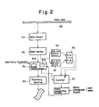
- Fig. 2 is a block diagram showing the constitution of a tape puncher
- Fig. 3 is a view showing the arrangement of command data recorded on a paper tape.
- Fig. 1 is a block diagram of a data input/output unit according to the present invention.
- numeral 1 denotes a control device
- 2 a read-only memory (hereafter abbreviated to "ROM”) storing a program necessary for operating the data input/output unit
- 3 a random-access memory (hereafter abbreviated to "RAM”) for temporarily storing data or the like read from a paper tape or the like
- 4 a tape reader, 5 a tape puncher, and 6 a printer for printing data read by the tape reader, data punched by the tape puncher 5, or data received from a host computer.
- Numeral 7 denotes an operator's panel having character keys, numeric keys, function keys and the like.
- the panel has an operation changeover switch for deciding whether operation is by a command from the host computer or whether the data input/output unit of the present invention is to operate independently.
- Numeral 8 is an interface circuit for interfacing the host computer.
- Numeral 9 designates a changeover circuit.
- the unit shown in Fig. 1 is capable of performing the following operations by itself. Specifically, data entered from the operator's panel 7 can be printed out immediately by the printer and the data can be stored in the RAM 3. In addition, after the results of the print-out are checked, errors in the data stored in the RAM 3 can be corrected. After the correction operation, the data stored in the RAM 3 can be printed out and punched in a paper tape as well. Furthermore, data read from the tape reader 4 can be printed out by the printer 6 and punched in a paper tape by the tape puncher 5 to create a copy of the paper tape. These operations can be performed simultaneously.
- the data input/output unit shown in Fig. 1 can be connected to a host computer by turning on the changeover circuit 9 through manipulation of the operation changeover switch provided on the operator's panel 7, and data can be transferred from the operator's panel 7 or tape reader 4 to the host computer through the RAM 3 or by by-passing the RAM.
- data transferred from the host computer can be recorded on a paper tape by the tape puncher 5, and the data can also be printed out by the printer 6.
- Fig. 2 is a block diagram showing the constitution of the tape puncher 5.
- numeral 5a denotes a gate circuit, 5b a data buffer, and 5c a puncher control circuit in which there are provided a register 5ca for storing two codes, and a gate 5cb. Data from the data buffer 5b passes through the register 5ca in serial fashion.
- Numeral 5d denotes a punching section, 5e a start data sensing circuit, 5f an end data sensing circuit, 5g a flip-flop circuit (hereafter referred to as an "FF circuit”), 5h a counter for counting the number of print characters, and 5i a parity designating circuit.
- FF circuit flip-flop circuit
- the circuit 5j If an odd number is designated by a parity changeover signal, the circuit 5j produces a parity signal P when the counted value delivered by the counter 5h is odd. If an even number is designated by the parity changeover signal, the circuit 5j produces a parity signal P when the counted value delivered by the counter 5h is even.
- one block of numerical control data recorded on a paper tape starts from an initial sequence number code and ends with an end-of-block code ";"
- the start data sensing circuit 5e which incorporates a decoder for sensing the sequence number code
- the circuit produces a "1" output.
- the end data sensing circuit 5f which incorporates a decoder for sensing the end-of-block code ";" senses this code, the circuit produces a "1" output.
- parity is added to data devoid of parity in data having a length of one block, with the data then being punched into a paper tape.
- Punch data from the data bus DB applied to the data buffer 5b via the gate circuit 5a is delivered to the puncher control circuit 5c.
- the start data sensing circuit 5e sets the FF circuit 5g.
- the set signal Q enables the counter 5h, the counted value of which has been cleared.
- Punch data thenceforth is delivered as an output by the data buffer 5b, the data passes through the register 5ca of the puncher control circuit 5c, the output whereof is a punch command delivered to the punching section 5d.
- the punching section 5d punches a code, which has received the punch command, into the paper tape.
- the puncher control circuit 5c produces a single pulse each time an item of punch data is applied thereto.
- the counter 5h counts the number of pulses to count the number of print characters.
- the FF circuit 5g is reset when the end-of-block code ";" is sensed in the print data delivered by the data buffer 5b.
- the reset signal Q halts the counting operation performed by the counter.
- the value of the count recorded by the counter 5h is then applied to the parity designating circuit 5i. If the value of the count indicates that a parity code is necessary, the parity signal P is produced.
- This signal is delivered to the puncher control circuit 5c. When this signal is received at the puncher control circuit 5c, a space code used as a parity code is inserted between the end-of-block code ";" stored in the register 5ca and the code stored ahead of the end-of-block code. The resulting punch command is delivered to the punching section 5d.
- a paper tape punched in this manner already has a parity code added thereto.
- Punch data from the data bus DB applied to the data buffer 5b via the gate circuit 5a is delivered to the puncher control circuit 5c.
- the start data sensing circuit 5e sets the FF circuit 5g.
- the set signal Q enables the counter 5h, the counted value of which has been cleared.
- Punch data thenceforth is delivered as an output by the data buffer 5b, the data passes through the register 5ca of the puncher control circuit 5c, the output whereof is a punch command delivered to the punching section 5d.
- the punching section 5d punches a code, which has received the punch command, into the paper tape.
- the puncher control circuit 5c produces a single pulse each time an item of punch data is applied thereto.
- the counter 5h counts the number of pulses to count the number of print characters.
- the FF circuit 5g is reset when the end-of-block code ";" is sensed in the print data delivered by the data buffer 5b.
- the reset signal Q halts the counting operation performed by the counter.
- the value of the count recorded by the counter 5h is then applied to the parity designating circuit 5i. If the value of the count indicates that a parity code is necessary, the parity signal P is produced. If the indication is that no parity code is necessary, then the parity signal P is not produced.
- This signal is delivered to the puncher control circuit 5c. When this signal is received at the puncher control circuit 5c, the signal is discriminated.
- the gate circuit 5cb is closed to one code if the code preceding the end-of-block code is a parity code, whereby the transmission of the one code (a space code serving as a parity code) is halted. As a result, no parity code whatsoever is punched into the paper tape. The remaining end-of-block codes are punched thereafter.
- the foregoing changeover is controlled by a control signal S generated on the host computer side or by the control device 1 itself and delivered via the gate circuit 5a.
- the tape puncher can be made to perform one or both of the two above-described operations.
- the tape puncher is not provided with the parity processing function of the type described above and is to perform an ordinary punching operation, it will suffice if the transfer of data to the start data sensing circuit 5e and end data sensing circuit 5f is suspended by the control signal S generated on the host computer side or by the control device 1 itself and delivered through the gate circuit 5a.
- the present invention is equipped with a processing function which not only enables a data input/output unit to operate in accordance with a command from a host computer in order to create a paper tape, print out transferred data and enter data, but which also enables the unit itself to be programmed independently to create a paper tape and print the data borne by the paper tape.
- the present invention therefore serves well as a transportable data input/output unit capable of servicing several numerical control devices.
- a tape puncher is provided with a counter for counting the number of print characters, a parity designating circuit for determining a parity change indicated by the value counted by the counter, and a puncher control circuit capable of adding and erasing a parity code.
- the puncher control circuit In response to a parity signal from the parity designating circuit, the puncher control circuit performs at least an addition or erasure of a parity code. Therefore, when punch data received from a host computer, or data read in from the tape reader 4 of the present input/output unit proper, is processed based on a command from the operator's panel or host computer and is punched out by the tape puncher, the operation of removing parity from data provided with parity, or of adding parity to data devoid of such parity, is capable of being performed by the data input/output unit itself or on the basis of a command from the host computer.
- a data input/output unit which is detachable from a host computer and in which the operation of removing parity from data provided with parity, or of adding parity to data devoid of such parity, is capable of being performed by the data input/output unit itself or on the basis of a command from the host computer.
- the present invention therefore serves well as a transportable data input/output unit capable of servicing several numerical control devices.
Landscapes
- Physics & Mathematics (AREA)
- General Physics & Mathematics (AREA)
- Engineering & Computer Science (AREA)
- Theoretical Computer Science (AREA)
- Accessory Devices And Overall Control Thereof (AREA)
- Numerical Control (AREA)
- Detection And Correction Of Errors (AREA)
Abstract
Un dispositif d'entrée et de sortie de données comprend un contrôleur (1), un perforateur de bande (5), un lecteur de bande perforée (4) ainsi qu'une imprimante (6) et peut fonctionner grâce à des commandes provenant d'un ordinateur principal. Un compteur (5h) comptant le nombre de caractères d'impression en un bloc, un circuit d'instruction de parité (5i) jugeant la parité du comptage du compteur et un circuit de commande de perforation (5c) capables d'ajouter ou d'effacer un code de parité sont prévus dans le perforateur de bande (5). Le circuit de commande de perforation (5c) peut ajouter ou effacer un code de parité conformément à un signal de parité provenant du circuit d'instruction de parité (5i).
Applications Claiming Priority (2)
| Application Number | Priority Date | Filing Date | Title |
|---|---|---|---|
| JP181826/82 | 1982-10-16 | ||
| JP57181826A JPS5971579A (ja) | 1982-10-16 | 1982-10-16 | デ−タ入出力装置 |
Publications (2)
| Publication Number | Publication Date |
|---|---|
| EP0152484A1 true EP0152484A1 (fr) | 1985-08-28 |
| EP0152484A4 EP0152484A4 (fr) | 1985-10-17 |
Family
ID=16107486
Family Applications (1)
| Application Number | Title | Priority Date | Filing Date |
|---|---|---|---|
| EP19830903221 Withdrawn EP0152484A4 (fr) | 1982-10-16 | 1983-10-14 | Dispositif d'entree et de sortie de donnees. |
Country Status (4)
| Country | Link |
|---|---|
| US (1) | US4636937A (fr) |
| EP (1) | EP0152484A4 (fr) |
| JP (1) | JPS5971579A (fr) |
| WO (1) | WO1984001646A1 (fr) |
Families Citing this family (1)
| Publication number | Priority date | Publication date | Assignee | Title |
|---|---|---|---|---|
| US5155735A (en) * | 1988-03-31 | 1992-10-13 | Wang Laboratories, Inc. | Parity checking apparatus with bus for connecting parity devices and non-parity devices |
Family Cites Families (29)
| Publication number | Priority date | Publication date | Assignee | Title |
|---|---|---|---|---|
| GB879187A (en) * | 1958-11-27 | 1961-10-04 | Creed & Co Ltd | Improvements in or relating to data processing apparatus |
| GB1062907A (en) * | 1964-07-24 | 1967-03-22 | Standard Telephones Cables Ltd | Improvements relating to the control of data tape movement |
| NL6509692A (fr) * | 1965-07-27 | 1967-01-30 | ||
| US3439341A (en) * | 1965-08-09 | 1969-04-15 | Lockheed Aircraft Corp | Hyphenation machine |
| US3482215A (en) * | 1966-12-09 | 1969-12-02 | Ricoh Kk | System for reversibly connecting a plurality of data processing equipments |
| DE1588051B2 (de) * | 1967-05-17 | 1973-08-23 | Verfahren zur erstellung eines digitalen befehlstraegers fuer programmgesteuerte werkzeugmaschinen | |
| US3632989A (en) * | 1967-05-17 | 1972-01-04 | Boehringer Gmbh Geb | Method and system for production of program controls for machine tools |
| US3629558A (en) * | 1969-09-12 | 1971-12-21 | Bendix Corp | Method for preparing control tapes |
| US3647041A (en) * | 1970-06-30 | 1972-03-07 | Ibm | System for determining line measure |
| US3854660A (en) * | 1972-04-26 | 1974-12-17 | Bendix Corp | Control system for multiple tape readers in an n/c system |
| DE2312881A1 (de) * | 1973-03-15 | 1974-10-03 | Olympia Werke Ag | Anordnung zum pruefen von datenlesegeraeten |
| US3923137A (en) * | 1973-04-05 | 1975-12-02 | Casio Computer Co Ltd | Information recording apparatus |
| US3890488A (en) * | 1973-12-05 | 1975-06-17 | Leupold & Stevens Inc | Digital print and punch tape recorder having read-write memory |
| US3915278A (en) * | 1974-03-21 | 1975-10-28 | Cpt Corp | Right hand margin adjustment feature for an automated typing system |
| JPS5129563A (fr) * | 1974-08-30 | 1976-03-12 | Mitsubishi Rayon Co | |
| US4042866A (en) * | 1974-09-20 | 1977-08-16 | Daihatsu Motor Company, Limited | Method of preparing NC tapes |
| US4010356A (en) * | 1974-10-15 | 1977-03-01 | Do All Company | Tape preparation system |
| US3975712A (en) * | 1975-02-18 | 1976-08-17 | Motorola, Inc. | Asynchronous communication interface adaptor |
| US4106091A (en) * | 1975-02-18 | 1978-08-08 | Motorola, Inc. | Interrupt status indication logic for polled interrupt digital system |
| US3979732A (en) * | 1975-02-18 | 1976-09-07 | Motorola, Inc. | Asynchronous status interlock circuit for interface adaptor |
| US4044328A (en) * | 1976-06-22 | 1977-08-23 | Bell & Howell Company | Data coding and error correcting methods and apparatus |
| JPS5334077A (en) * | 1976-09-10 | 1978-03-30 | Oki Electric Ind Co Ltd | Making-out method and device of nc-tape |
| CH622444A5 (fr) * | 1977-04-04 | 1981-04-15 | Gruenenfelder H Eltex Elektron | |
| JPS6127001Y2 (fr) * | 1980-07-10 | 1986-08-12 | ||
| JPS5769312A (en) * | 1980-10-13 | 1982-04-28 | Fanuc Ltd | Numerical controller incorporating optional block skipping function |
| US4393493A (en) * | 1980-11-10 | 1983-07-12 | International Telephone And Telegraph Corporation | Automatic protection apparatus for span lines employed in high speed digital systems |
| JPS57113113A (en) * | 1980-12-30 | 1982-07-14 | Fanuc Ltd | Generating method for curved surface |
| US4509139A (en) * | 1982-01-21 | 1985-04-02 | Creager & Company | Binary data storage and retrieval system for serial interface communications and archival access |
| JPH05317037A (ja) * | 1991-10-30 | 1993-12-03 | Tonen Corp | 酵母erd2遺伝子とそのリガンドとしての小胞体局在蛋白質をコードする遺伝子とを含む共発現系及びそれを利用する有用ポリペプチドの製造法 |
-
1982
- 1982-10-16 JP JP57181826A patent/JPS5971579A/ja active Pending
-
1983
- 1983-10-14 EP EP19830903221 patent/EP0152484A4/fr not_active Withdrawn
- 1983-10-14 US US06/651,996 patent/US4636937A/en not_active Expired - Fee Related
- 1983-10-14 WO PCT/JP1983/000357 patent/WO1984001646A1/fr not_active Ceased
Also Published As
| Publication number | Publication date |
|---|---|
| WO1984001646A1 (fr) | 1984-04-26 |
| US4636937A (en) | 1987-01-13 |
| JPS5971579A (ja) | 1984-04-23 |
| EP0152484A4 (fr) | 1985-10-17 |
Similar Documents
| Publication | Publication Date | Title |
|---|---|---|
| US4501998A (en) | Numerical controller equipped with optional block skip function | |
| EP0067267B1 (fr) | Système d'ordinateur équipé de terminaux pour le traitement de documents et procédé de fonctionnement de celui-ci | |
| SE439899B (sv) | Textredigeringsanordning vid elektroniska skrivmaskiner | |
| EP0333614A2 (fr) | Fonction de réglage de tabulateur pour une machine à écrire électronique | |
| US4636937A (en) | Data input/output unit | |
| EP0249794B1 (fr) | Insertion automatique de codes d'arrêt dans un appareil pour traitement de mots | |
| US4677543A (en) | Transportable and detachable data input/output unit providing automatic character insertion or deletion | |
| EP0122292A1 (fr) | Appareil d'entree et de sortie de donnees | |
| EP0121574A1 (fr) | Appareil d'entree et de sortie de donnees | |
| US3781813A (en) | Machine log system | |
| JPS5969874A (ja) | デ−タ入出力装置 | |
| EP0327780B1 (fr) | Fonction pour le remplacement limité dans un mot pour une machine à écrire électronique | |
| JPS5969839A (ja) | デ−タ入出力装置 | |
| US5664209A (en) | Document processing apparatus for processing information having different data formats | |
| JP3250118B2 (ja) | 印刷装置のデータ管理方式 | |
| JP2583881B2 (ja) | カ−ドによる管理情報処理方法 | |
| JPH0456337B2 (fr) | ||
| JPS5969872A (ja) | デ−タ入出力装置 | |
| JPS5972531A (ja) | デ−タ入出力装置 | |
| JPS5855543B2 (ja) | 帳票読取装置における読取デ−タ取消し方法 | |
| JPH0113150B2 (fr) | ||
| JPH01301276A (ja) | プリンタ | |
| JPS5971513A (ja) | デ−タ入出力装置 | |
| JPS6134994B2 (fr) | ||
| JPH04296910A (ja) | 数値制御装置 |
Legal Events
| Date | Code | Title | Description |
|---|---|---|---|
| PUAI | Public reference made under article 153(3) epc to a published international application that has entered the european phase |
Free format text: ORIGINAL CODE: 0009012 |
|
| 17P | Request for examination filed |
Effective date: 19840928 |
|
| AK | Designated contracting states |
Designated state(s): DE FR GB |
|
| 17Q | First examination report despatched |
Effective date: 19861223 |
|
| STAA | Information on the status of an ep patent application or granted ep patent |
Free format text: STATUS: THE APPLICATION IS DEEMED TO BE WITHDRAWN |
|
| 18D | Application deemed to be withdrawn |
Effective date: 19880503 |
|
| RIN1 | Information on inventor provided before grant (corrected) |
Inventor name: MIZUNO, YUTAKA Inventor name: SEKI, MASAKI Inventor name: KISHI, HAJIMU |