EP0153756A2 - Scheibenführung für Kraftfahrzeugtüren - Google Patents
Scheibenführung für Kraftfahrzeugtüren Download PDFInfo
- Publication number
- EP0153756A2 EP0153756A2 EP85102270A EP85102270A EP0153756A2 EP 0153756 A2 EP0153756 A2 EP 0153756A2 EP 85102270 A EP85102270 A EP 85102270A EP 85102270 A EP85102270 A EP 85102270A EP 0153756 A2 EP0153756 A2 EP 0153756A2
- Authority
- EP
- European Patent Office
- Prior art keywords
- door glass
- door
- lip
- glass run
- run
- Prior art date
- Legal status (The legal status is an assumption and is not a legal conclusion. Google has not performed a legal analysis and makes no representation as to the accuracy of the status listed.)
- Granted
Links
Images




Classifications
-
- B—PERFORMING OPERATIONS; TRANSPORTING
- B60—VEHICLES IN GENERAL
- B60J—WINDOWS, WINDSCREENS, NON-FIXED ROOFS, DOORS, OR SIMILAR DEVICES FOR VEHICLES; REMOVABLE EXTERNAL PROTECTIVE COVERINGS SPECIALLY ADAPTED FOR VEHICLES
- B60J1/00—Windows; Windscreens; Accessories therefor
- B60J1/08—Windows; Windscreens; Accessories therefor arranged at vehicle sides
- B60J1/12—Windows; Windscreens; Accessories therefor arranged at vehicle sides adjustable
- B60J1/16—Windows; Windscreens; Accessories therefor arranged at vehicle sides adjustable slidable
- B60J1/17—Windows; Windscreens; Accessories therefor arranged at vehicle sides adjustable slidable vertically
-
- B—PERFORMING OPERATIONS; TRANSPORTING
- B60—VEHICLES IN GENERAL
- B60J—WINDOWS, WINDSCREENS, NON-FIXED ROOFS, DOORS, OR SIMILAR DEVICES FOR VEHICLES; REMOVABLE EXTERNAL PROTECTIVE COVERINGS SPECIALLY ADAPTED FOR VEHICLES
- B60J10/00—Sealing arrangements
- B60J10/20—Sealing arrangements characterised by the shape
-
- B—PERFORMING OPERATIONS; TRANSPORTING
- B60—VEHICLES IN GENERAL
- B60J—WINDOWS, WINDSCREENS, NON-FIXED ROOFS, DOORS, OR SIMILAR DEVICES FOR VEHICLES; REMOVABLE EXTERNAL PROTECTIVE COVERINGS SPECIALLY ADAPTED FOR VEHICLES
- B60J10/00—Sealing arrangements
- B60J10/20—Sealing arrangements characterised by the shape
- B60J10/23—Sealing arrangements characterised by the shape assembled from two or more parts
- B60J10/235—Sealing arrangements characterised by the shape assembled from two or more parts the parts being joined along their longitudinal direction
-
- B—PERFORMING OPERATIONS; TRANSPORTING
- B60—VEHICLES IN GENERAL
- B60J—WINDOWS, WINDSCREENS, NON-FIXED ROOFS, DOORS, OR SIMILAR DEVICES FOR VEHICLES; REMOVABLE EXTERNAL PROTECTIVE COVERINGS SPECIALLY ADAPTED FOR VEHICLES
- B60J10/00—Sealing arrangements
- B60J10/70—Sealing arrangements specially adapted for windows or windscreens
- B60J10/74—Sealing arrangements specially adapted for windows or windscreens for sliding window panes, e.g. sash guides
Definitions
- This invention relates to a construction of a door glass guide, and particularly to improvements in a construction of a door glass guide porovided in a door frame of a motor vehicle's door with the door frame.
- a construction of a door glass guide in a motor vehicle with a door frame is normally of such arrangement that a door glass run 3 being a generally U-shape in cross section is provided in a guide portion 2 of a door frame 1, whereby the door glass run 3 guides the front or rear end edge of a door glass 4 and restrains the same in a direction of thickness of the door glass 4.
- the door glass run 3 is provided with an outer lip 3A and an inner lip 3B, both of which are obliquely extending from the forward end portion of the U-shaped section toward the center of the section.
- the outer lip 3A and the inner lip 3B are brought into sliding contact with the inner and outer surfaces of the front or rear end edge 4A of the door glass 4, so as to guide the door glass 4 in the opening or closing direction.
- the outer lip 3A and the inner lip 3B are elastically deformable within a predetermined range in the direction of the thickness of the door glass 4.
- the cross-sectional shape of a door glass of a side door in a motor vehicle, particularly a passenger car is normally a circularly arcuate shape, and a sliding path 5 of the door glass 4 has a circularly accuate shape as shown in Fig. 21 for example.
- a plane of rotation 6 of an arm, not shown, of a window regulator for raising or lowering the door glass 4 is a plane in the substantially vertical direction.
- the door glass 4 urges the outer lip 3A of the door glass run 3 against the outer surface portion 1A of the door frame 11 deform the outer lip 3A as shown in Fig. 20.
- the state of the door glass 4 in this case is indicated by a two-dot chain line 4E in Fig. 21.
- the outer surface of the door glass 4 may be bulged outwardly from the outer surface of the door frame 1 in some cases, thereby presenting the disadvantages of that the appearance of the vehicle is deteriorated and the characteristics of aerodynamics is lowered during the running of the motor vehicle at high speed.
- the means for introducing the forward end to the center of the door glass run for example, there are a construction, wherein the proximal end portion of the lip, to which the door glass is shifted, is obliquely extended and reinforced by an insert, as disclosed in West German DE 3106909A1, and another construction, wherein the proximal end portion of the lip, to which the door glass is shifted, is formed of a hard material and extended obliquely, as disclosed in Japanese Patent Kokai (Laid-Open) No. 164420/83.
- the means for controlling a deformation value of the lip for example, there is such a means that a portion of the side wall of the main body of door glass run positioned on the rear surface of the lip of the door glass run is bulged in the direction of the thickness thereof and this bulged-out portion is caused to interfere with the rear surface of the lip so as to restrict the maximum displacement value of the lip, as disclosed in Japanese Utility Model Kokai (Laid-Open) No. 122366/84.
- the present applicant proposes, in the present Application, a door construction in a motor vehicle, wherein a spacer is interposed in the rear of a lip of the door glass run, whereby the lip is not pushed outwardly in the widthwise direction thereof and deformed by the door glass.
- the aforesaid spacer is only elastically coupled in the rear of the lip, thereby presenting the disadvantages of that it is difficult to position the spacer and in the case of the parts before being assembled to the door of the motor vehicle or during assembling work, a slight burr of the lip may cause the fall-off of the spacer.
- the aforesaid spacer is coupled in the rear of the lip and the lip is urged against the outer surface of the door glass, thereby presenting the disadvantage of that the sliding resistance between the lip and the door glass is increased during the opening or closing of the door glass, to thereby increase the operation load of the window regulator.
- the primary object of the present invention is to provide a construction of a door glass guide in a motor vehicle, wherein a spacer is partially interposed in gaps formed between the inner lip and the base portion of the door glass run and between the outer lip and the base portion so as to prevent the door glass from moving outwardly from the vehicle body, so that, even when the door glass is raised or lowered during the running of the motor vehicle at high speed, the upper side portion and the oblique portion of the door glass can run smoothly into the door glass run.
- Another object of the present invention is to provide a construction of a door glass guide in a motor vehicle, wherein the door glass is not pushed outwardly from the vehicle body by the window regulator when the door glass is fully closed.
- a further object of the present invention is to provide a construction of a door glass guide in a motor vehicle, wherein the spacer can be easily positioned.with respect to the door glass run and cannot fall off easily.
- a still further object of the present invention is to provide a construction of a the door glass guide in a motor vehicle, the sliding resistance of a spacer is low in its increase during the opening or closing of the door glass.
- the present invention contemplates that in a construction of a door glass guide in a motor vehicle, comprising a door glass run including a main body of the door glass run secured to a guide portion of a door frame, being opposed to an end edge of a door glass and a lip, which is extending from an end portion directed to the center of said door glass toward the center of the main body of the door glass run in the widthwise direction thereof and toward the outer periphery of said door frame, being in sliding contact with the glass surfaces at the end edge of said door glass, and guiding said door glass in the opening and closing directions, wherein there is provided a spacer being opposed to at least a portion of the door glass run in the longitudinal direction, disposed between the lip and the main body of the door glass run in the rear of the lip in the direction of the thickness of said door glass, and regulating the deformation of the lip in the widthwise direction of the door glass run.
- the present invention contemplates that in a construction of a door glass guide in a motor vehicle, when the door glass is positioned immediately before the upper side edge and the oblique edge thereof are to run into the door glass run coupled into the upper side portion and the oblique side portion of the door frame, a spacer is interposed between the base portion and the outer lip of the door glass run within a limited scope of the door glass run in the proximity of-a position where the upper ends of the forward side edge and the rear side edge of the door glass are located, respectively, and another spacer is interposed between the base portion and the inner lip of the door glass run within a limited scope of the door glass run in the proximity of a position where the lower ends of the forward side edge and the rear side edge of the door glass are located, respectively.
- the present invention contemplates that, in a construction of a door glass guide in a motor vehicle, wherein a spacer is interposed in the rear of a lip of a door glass run, whereby the lip is not pushed outwardly in the widthwise direction thereof and deformed by the door glass, and comprising: a door glass run including a main body of the door glass run secured to a guide portion of a door frame in a door of a motor vehicle, being opposed to an end edge of the door glass and lips, which are extending from end portions directed to the center of the door glass toward the center of the main body of the door glass run in the widthwise direction thereof and toward the outer periphery of the door frame, being in sliding contact with the glass surfaces at the end edge of the door glass, and guiding the door glass in the opening or closing direction; and a spacer being opposed to at least a portion of the door glass run in the longitudinal direction thereof, disposed between one lip and the main body of the door glass run in the rear of the lip in the direction of the
- the present invention contemplates that a spacer is disposed in the rear of the outer lip of the door glass run provided on the upper side of the door frame.
- the spacer is disposed in the rear of the outer lip, which is located at a position close to the door beltline, of the door glass run provided on the longitudinal side of the door frame, so that the door glass can be prevented from being displaced outwardly by a window regulator.
- the present invention contemplates that a positioning rib is projected from a portion of the spacer, which is brought into contact with the main body of the door glass run and a positioning hole for receiving the positioning rib is formed in the main body of the door glass run in opposed relationship to the positioning rib.
- the present invention contemplates that a pawl penetrating through and projecting out of the positioning hole and spreading in the lateral direction is integrally formed with the forward end of the positioning rib.
- the positioning rib integrally formed on the spacer is received in the positioning hole formed in the door glass run, so that the spacer can be reliably positioned and prevented from falling off.
- the present invention contemplates that chamfering is applied to at least one of end portions in the moving direction of the door glass, of a surface of the spacer, which is in contact with the rear surface of the lip of the door glass run.
- chamfering is applied to an end portion or portions in the opening or closing direction of the door glass, of the surfaces of the spacer, which are in contact with the lip of the door glass run, whereby the area of the spacer contacting the lip is reduced, so that the sliding resistance of the lip can be lowered during the opening or closing of the door glass.
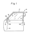
- Fig. 1 shows a state where an upper side edge 11 and an oblique edge 12 of the door glass 10 are positioned immediately before the edges 11 and 12 run into a door glass run 15 coupled into an upper side portion 17 and an oblique side portion 18 of a door frame 16.
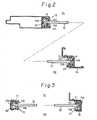
- a spacer 20 is interposed between a base portion 15A and an outer lip 15B of the door glass run 15 within a limited scope of the door glass run 15 in the proximity of a position where there are positioned an upper end 13A of a forward side edge 13 and an upper end 14A of a rear side edge 14 of the door glass 10, as shwon in Fig. 2.
- a spacer 21 is interposed between the base portion 15A and an inner lip 15C of the door glass run 15 within a limited scope of the door glass run 15 in the proximity of a position where there are positioned a lower end 13B of the forward side edge 13 and a lower end 14B of the rear side edge 14 of the door glass 10, as shown in Fig. 3.
- the spacers 20 and 21 are preferably formed of a material having a low deflection, such as solid rubger or synthetic resin.
- the edges 11 and 12 can be prevented from moving outwardly from the vehicle body by the spacers 20 and 21.
- Denote 22 shows a guide portion of the door frame 16, R1 and R2 shows an inner side and an outer side of the door glass 10, respectively.
- the upper side edge 11 and the oblique edge 12 of the door glass 10 can be made to run smoothly into the door glass run 15.
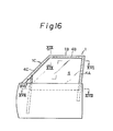
- a door glass run 40 including a main body 36 in as door 29 of a motor vehicle, being opposed to an end edge 34A of the door glass 34 and lips 38, which are extending from end portions directed to the center of the door glass 34 toward the center of the main body 36 of the door glass run in the widthwise direction thereof and toward the outer periphery of the door frame 30, being in sliding contact with the glass surfaces at the end edge 34A of the door glass 34, and guiding the door glass 34 in the opening or closing direction; and a spacer 42 being opposed to at least a portion of the door glass run 40 in the longitudinal direction thereof, disposed between the lip 38 and the main body 36 of the door glass run in the rear of the lip 38 in the direction of the thickness of the door glass 34, and regulating the deformation of the lip 38 outwardly in the widthwise direction of the door glass run 40; the spacer 42 is disposed in the rear of an outer lip
- the lips 38 comprises the outer lip 38A being in contact with the outer surface of the door glass 34 and an inner lip 38b being in contact with the compartment's side surface of the door glass 34.
- the main body 36 of the door glass run is of a generally U-shape in cross section and the U-shape is respectively, integrally formed at the forward ends on the side of the opening thereof with the outer lip 38A and the inner lip 38B, as shown in the drawing.
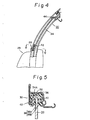
- the spacer 42 is disposed in the rear of the outer lip 38A at a position close to the door beltline in the door glass run 40 provided on the longitudinal side 30 of the door frame 30, so that, even if the door glass 34 is subjected to a force of pushing the door glass 34 outwardly by the window regulator when the door glass 34 is fully closed, the door glass 34 can be prevented from being displaced outwardly (Refer to Fig. 5).
- the door glass 34 is in contact with the outer lip 38A and the inner lip 38B of the door glass run 40 uniformly in the vertical direction of the door frame, so that the sealing performance can be prevented from being lowered by the door glass run 40.
- the outward bulging of the door glass 34 is regulated, so that the appearance of the motor vehicle and the characteristics of aerodynamics can be prevented from lowering when the door glass 34 is fully closed.
- the spacer 42 has been mounted to the door glass run 40 at the'position close to the door beltline.
- a spacer 44 may be disposed in the rear of the outer lip 38A of the glass run 40 provided on the upper side 30B of the door frame 30, as indicated by two-dot chain lines in Fig. 4.
- the main body 40A of the door glass run 40 has been formed into the generally U-shape in cross section, however, the present invention need not necessarily be limited to this, and the main body of the door glass run may be formed into other shapes, such as an L-shape.
- the present invention with the above arrangement can offer such an outstanding advantage that the door glass 34 can be reliably prevented from being pushed outwardly by the window regulator when the door glass 34 is fully closed.
- a door glass run 60 including a main body 56 of the door glass run secured to a guide portion 52 of a door frame 50 in a door, not shown, of a motor vehicle, being opposed to an end edge 54A of the door glass 54 and lips 58, which are extending from end portions directed to the center of the door glass 54 toward the center of the main body 56 of the door glass run 60 in the widthwise direction thereof and toward the outer periphery of the door frame 50, being in sliding contact with the glass surfaces at the end edge 54A of the door glass 54, and guiding the door glass 54 in the opening or closing direction; and a spacer 62 being opposed to at least a portion of the door glass run 60 in the longitudinal direction thereof, disposed between the lip 58 and the main body 56 of the door glass run in the rear of the lip 58 in the direction of the thickness of the door glass 54, and regulating the deformation of the lip 58
- the lips 58 comprise an outer lip 58A being in contact with the outer surface of the door glass 54 and an inner lip 58B being in contact with the compartment's side surface of the door glass 54.
- the main body 56 of the door glass run is of a generally U-shape in cross section and the U-shape is respectively, integrally formed at the forward ends on the side of the opening thereof with the outer lip 58A and the inner lip 58B, as shown in the drawing.
- the process of mounting the spacer 62 to the door glass run 60 includes the steps of pulling up the outer lip 58A or the inner lip 58B on the mounting side, inserting and coupling the positioning rib 64 of the spacer 62 into the positioning hole 66 formed in the main body 56 of the door glass run, and restoring the outer lip 58A or the inner lip 58B, which has been pulled up, to the original position, thus completing the process.
- the positioning rib 64 of the spacer 62 is inserted and coupled into the positioning hole 26 formed in the main body 56 of the door glass run, so that the positioning of the door glass run 60 in the longitudinal direction can be reliably carried out.
- the lengths in the direction of the spacers 62 of in spaces 59A and 59B formed inside the outer lip 58A and the inner lip 58B are each shorter than the spacer 62 having no positioning rib 64 by the length of the positioning rib 64, so that the spacer 62 cannot fall down unless the outer lip 58A or the inner lip 58B is turned over to a great extent.
- the spacer 72 in this fourth embodiment is constructed such that the positioning rib 64 has a length of penetrating through the main body 56 of the door glass run and projecting to the other side, and the projecting end portion is formed with pawls 68A and 68B, which are extending in directions opposite to each other.
- the fall-off of the spacer is further reliably prevented, and particularly, even if the outer lip 58A or the inner lip 58B is pulled up and turned over, the fall-off is prevented.
- the spacer 72 in the fourth embodiment as shown in Figs. 9 and 10 has been formed at the forward end portion of the positioning rib 64 thereof with the pair of pawls 68A and 68B extending in the direction perpendicularly intersecting the longitudinal axis of the positioning rib 64, however, the pawls of the present invention need not necessarily be limited to this shapes, and pawls 78A and 78 B , formed into substantially triangular shapes, may be provided as in a spacer 74 according to the third embodiment shown in Fig. 11 for example.
- the positioning rib 64 of the spacer 62, 72 or 74 has been inserted and coupled into the positioning hole 66 formed in the base portion 56A of the main body 56 of the door glass run being of the generally U-shape in cross section, however, the present invention need not necessarily be limited to this, and the positioning rib of the spacer may be inserted and coupled into one of holes formed in a pair of side portions 56B of the main body 56 of the door glass run being of the generally U-shape in cross section.
- the main body of the door glass run has been formed into the generally U-shape in cross section, however, the present invention need not necessarily be limited to this, and any other shape such as an L-shape may be adopted.
- the present invention with the above-described arrangement can offer such an outstanding advantage that the positioning of the spacer can be easily and reliably performed and the spacer can be prevented from falling off from the door glass run.
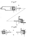
- the spacer 92 for the door glass run 90 being opposed at least a portion of the door glass run 90 in the longitudinal direction thereof, disposed between the lip 88 and the main body 16 of the door glass run in the rear of the lip 88 in the direction of the thickness of the door glass 84, and regulating the deformation of the lip 88 outwardly in the widthwise direction of the door glass run 90
- in the door glass run 90 including the main body 86 of the door glass run secured to the guide portion 82 of the door frame 80 in the door, not shown, of a motor vehicle being opposed to the end edge 84A of the door glass 84 and lips 88, which are extending from the end portions directed to the center of the door glass 84 toward the center of the main body 86 of the door glass run in the widthwise direction thereof and toward the outer periphery of the door frame 86, being in sliding contact with the glass surfaces at the end edge 84A of the door glass 84, and guiding the door glass
- the spacer 92 is formed into two continuous wave shapes in cross section, which substantially correspond to the sectional shape of an inner space 89 in the rear of the lip 88 of the door glass run 90, and chamfering is applied to the opposite ends of the spacer 92 in a direction perpendicularly intersecting the aforesaid cross section, namely, the moving direction of the door glass 84 (the longitudinal direction of the door glass run), whereby two. generally pyramidal raised portions, large and small, 92A and 92B are formed.
- the positioning rib 94 is projectingly provided on a portion of the spacer being in contact with the main body 86 of the door glass run and the positioning hole 96 for receiving the positioning rib 94 is formed in the main body 86 of the door glass run in opposed relationship to the positioning rib 94.
- Reference numerals 98A and 98B indicate pawls for locking against dislodging, which are integrally formed on the forward end portion of the rib 94 and projecting in a direction perpendicularly intersecting the longitudinal axis of the positioning rib 94.
- the lips 18 comprise an outer lip 88A being in contact with the outer surface of the door glass 84 and an inner lip 88B being in contact with the compartment's side surface of the door glass 84.
- the main body 86 of the door glass run is of a generally U-shape in cross section and the U-shape is respectively, integrally formed at the forward ends on the side of the opening thereof with the outer lip 88A and the inner lip 88B, as shown in the drawing.
- the process of mounting the spacer 92 to the door glass run 90 includes the steps of pulling up the outer lip 88A or the inner lip 88B on the mounting side, inserting and coupling the positioning rib 94 of the spacer 92 into the positioning hole 96 formed in the main body 86 of the door glass run, and restoring the outer lip 88A or the inner lip 88B, which has been pulled up, to the original position, thus completing the process.
- the raised portions 92A and 92B of the spacer 92 which are in contact with the rear surface of the lip, are chamfered at the opposite ends thereof in the moving direction of the door glass 84, the raised portions 22A and 22B are formed into two generally pyramidal shapes.
- the raised portion 92A and 92B are in point-to-point contact with the rear surface of the lip 88, whereby the sliding resistance of the lip 88 to the door glass 84 during the opening or closing operation of the door glass 84 can be reduced.
- the positioning rib 94 of the spacer 92 is inserted and coupled into the positioning hole 96 of the main body 86 of the door glass run, so that the positioning of the door glass run 90 in the longitudinal direction can be reliably carried out.
- the lengths in the longitudinal direction of the spacers 92 of spaces 89A and 89B formed inside the outer lip 88A and the inner lip 88B are each shorter than the spacer 92 having no positioning rib 94 by the length of the positioning rib 94, so that the spacer 92 cannot fall off unless the outer lip 88A or the inner lip 88B is turned over to a great extent.
- the spacer 92 is constructed such that the positioning rib 94 has a length of penetrating through the main body 86 of the door glass run and projecting to the other side, and the thus projecting end portion is formed with pawls 98A and 98B, which are extending in directions opposite to each other, so that, even if the outer lip 88A or the inner lip 88B is pulled up and turned over, the fall-off of the spacer 92 can be prevented.
- the raised portions 92A and 92B of the spacer 92 are chamfered at the opposite ends thereof in the moving direction of the door glass 84 and formed into the generally pyramidal shapes, however, the present invention need not necessarily be limited to this, and such an arrangement may be adopted that the raised portions 92A and 92B may be ones which are substantially in point-to-point contact with the rear surface of the lip 88 due to the chamfering, and consequently, the chamfering may be applied to only one side as shown in Fig. 15.
- the spacer 92 has been formed with the two raised portions, large and small, 92A and 92B, however, the present invention need not necessarily be limited to this, and the spacer 92 may have one of the raised portions, namely, only 92A, for example.
- the present invention with the above-described arrangement can offer such an advantage that the sliding resistance of the lips of the door glass run due to the mounting of the spacer during the opening or closing operation of the door glass can be reduced.
Landscapes
- Engineering & Computer Science (AREA)
- Mechanical Engineering (AREA)
- Seal Device For Vehicle (AREA)
Applications Claiming Priority (8)
| Application Number | Priority Date | Filing Date | Title |
|---|---|---|---|
| JP29750/84U | 1984-03-01 | ||
| JP1984029750U JPS60142120U (ja) | 1984-03-01 | 1984-03-01 | 自動車のドア構造 |
| JP1984126867U JPS6141014U (ja) | 1984-08-21 | 1984-08-21 | ドアガラスラン用スペ−サ |
| JP126866/84U | 1984-08-21 | ||
| JP1984126870U JPS6141016U (ja) | 1984-08-21 | 1984-08-21 | 自動車のドアガラスガイド構造 |
| JP126867/84U | 1984-08-21 | ||
| JP126870/84U | 1984-08-21 | ||
| JP1984126866U JPS6141022U (ja) | 1984-08-21 | 1984-08-21 | 自動車のドアガラスガイド構造 |
Publications (3)
| Publication Number | Publication Date |
|---|---|
| EP0153756A2 true EP0153756A2 (de) | 1985-09-04 |
| EP0153756A3 EP0153756A3 (en) | 1988-03-02 |
| EP0153756B1 EP0153756B1 (de) | 1990-05-16 |
Family
ID=27459118
Family Applications (1)
| Application Number | Title | Priority Date | Filing Date |
|---|---|---|---|
| EP85102270A Expired - Lifetime EP0153756B1 (de) | 1984-03-01 | 1985-02-28 | Scheibenführung für Kraftfahrzeugtüren |
Country Status (3)
| Country | Link |
|---|---|
| US (1) | US4663888A (de) |
| EP (1) | EP0153756B1 (de) |
| DE (1) | DE3577677D1 (de) |
Cited By (2)
| Publication number | Priority date | Publication date | Assignee | Title |
|---|---|---|---|---|
| FR2634702A2 (fr) * | 1987-12-23 | 1990-02-02 | Mesnel Sa Ets | Nouveau profile formant pince pour joints d'etancheite d'automobile |
| EP0799736A1 (de) * | 1996-04-01 | 1997-10-08 | Draftex Industries Limited | Dichtungs-und Führungsleisten und Sicherheitssystem für motorisch angetriebeneFahrzeugfenster |
Families Citing this family (12)
| Publication number | Priority date | Publication date | Assignee | Title |
|---|---|---|---|---|
| JPS6343819A (ja) * | 1986-08-09 | 1988-02-24 | Toyoda Gosei Co Ltd | 自動車用ドアガラスラン |
| FR2627835B1 (fr) * | 1988-02-26 | 1991-05-17 | Hutchinson | Coulisse d'etancheite de glace mobile, notamment de vitre de vehicule automobile |
| US5217786A (en) * | 1990-10-05 | 1993-06-08 | The Standard Products Company | Glass run strip with chamfered edge transition |
| JP3931023B2 (ja) * | 2000-07-06 | 2007-06-13 | 豊田合成株式会社 | ドアガラスラン |
| JP3713547B2 (ja) * | 2000-08-30 | 2005-11-09 | 豊田合成株式会社 | 自動車用ガラスラン |
| US7062880B2 (en) * | 2002-10-19 | 2006-06-20 | General Motors Corporation | Stabilizer clip for window assembly |
| JP2005008140A (ja) * | 2003-05-26 | 2005-01-13 | Toyoda Gosei Co Ltd | 自動車用ガラスラン |
| JP4388355B2 (ja) * | 2003-12-04 | 2009-12-24 | 株式会社アステア | 樹脂製ロアサッシュ |
| JP4375273B2 (ja) * | 2005-03-31 | 2009-12-02 | 豊田合成株式会社 | 自動車用ガラスラン |
| US8001728B2 (en) * | 2006-12-27 | 2011-08-23 | Toyoda Gosei Co., Ltd. | Glass run and its attaching structure |
| JP6009264B2 (ja) * | 2012-07-31 | 2016-10-19 | 西川ゴム工業株式会社 | ガラスラン |
| JP7095263B2 (ja) * | 2017-11-10 | 2022-07-05 | 株式会社アイシン | 車両ドアのウインドガラス支持構造 |
Family Cites Families (6)
| Publication number | Priority date | Publication date | Assignee | Title |
|---|---|---|---|---|
| FR1373275A (fr) * | 1962-10-02 | 1964-09-25 | Ford France | Assemblage à glissière pour élément coulissant |
| US3401075A (en) * | 1965-07-14 | 1968-09-10 | Standard Products Co | Channel shaped strip structure |
| DE7001383U (de) * | 1970-01-09 | 1970-05-06 | Draftex Gmbh | U-foermig profilierte fensterfuehrung. |
| DE2827372A1 (de) * | 1978-06-22 | 1980-01-03 | Audi Nsu Auto Union Ag | Dichtung fuer eine in einem fahrzeug hoehenverstellbar gefuehrte scheibe |
| JPS6022198Y2 (ja) * | 1980-03-11 | 1985-07-02 | 日産自動車株式会社 | 自動車のガラスランチヤンネル |
| JPS584079A (ja) * | 1981-06-26 | 1983-01-11 | 日産自動車株式会社 | ドアガラスの昇降ガイド機構 |
-
1985
- 1985-02-28 US US06/706,616 patent/US4663888A/en not_active Expired - Fee Related
- 1985-02-28 EP EP85102270A patent/EP0153756B1/de not_active Expired - Lifetime
- 1985-02-28 DE DE8585102270T patent/DE3577677D1/de not_active Expired - Lifetime
Cited By (2)
| Publication number | Priority date | Publication date | Assignee | Title |
|---|---|---|---|---|
| FR2634702A2 (fr) * | 1987-12-23 | 1990-02-02 | Mesnel Sa Ets | Nouveau profile formant pince pour joints d'etancheite d'automobile |
| EP0799736A1 (de) * | 1996-04-01 | 1997-10-08 | Draftex Industries Limited | Dichtungs-und Führungsleisten und Sicherheitssystem für motorisch angetriebeneFahrzeugfenster |
Also Published As
| Publication number | Publication date |
|---|---|
| EP0153756B1 (de) | 1990-05-16 |
| EP0153756A3 (en) | 1988-03-02 |
| DE3577677D1 (de) | 1990-06-21 |
| US4663888A (en) | 1987-05-12 |
Similar Documents
| Publication | Publication Date | Title |
|---|---|---|
| EP0153756B1 (de) | Scheibenführung für Kraftfahrzeugtüren | |
| EP0161685B1 (de) | Aufbau eines Kraftfahrzeugtürrahmens | |
| US6493992B2 (en) | Glass run and attachment structure therefor | |
| US7055285B2 (en) | Trim and glass run attachment structure in vehicle door | |
| US5732509A (en) | Guide and sealing system vehicle window flush with body surface | |
| EP0171821B1 (de) | Scheibenführung bei Kraftfahrzeugen | |
| JP5163795B2 (ja) | ガラスランの取付構造 | |
| US20070271853A1 (en) | Glass run mounting structure | |
| EP0131959B1 (de) | Türkonstruktion im Kraftfahrzeug | |
| JP2004098768A (ja) | 車両用インナーベルトモール、及びその取付構造 | |
| EP0133529A2 (de) | Bauart einer Tür in Kraftfahrzeug | |
| US5150542A (en) | Glass runner structure of vehicular door | |
| US11577593B2 (en) | Glass run | |
| US5365698A (en) | Door glass run for automobile | |
| EP0476874B1 (de) | Struktur für Kraftfahrzeugfenster-Führungskanal | |
| GB2071190A (en) | Automotive vehicle door window glass run channel | |
| JPS6347645B2 (de) | ||
| EP0133528A2 (de) | Bauart einer Tür in Kraftfahrzeug | |
| CN119384365A (zh) | 密封型材条和用于滑动窗的密封装置 | |
| EP0188212B1 (de) | Kraftfahrzeugfensterführungssystem | |
| EP0163208B1 (de) | Rahmenkonstruktion einer Kraftfahrzeugtür | |
| JPH0331606Y2 (de) | ||
| JP3284847B2 (ja) | シール装置 | |
| JP3727583B2 (ja) | 車両用ドア | |
| JP3765938B2 (ja) | 自動車用ドアガラスの案内装置 |
Legal Events
| Date | Code | Title | Description |
|---|---|---|---|
| PUAI | Public reference made under article 153(3) epc to a published international application that has entered the european phase |
Free format text: ORIGINAL CODE: 0009012 |
|
| AK | Designated contracting states |
Designated state(s): DE FR GB |
|
| PUAL | Search report despatched |
Free format text: ORIGINAL CODE: 0009013 |
|
| AK | Designated contracting states |
Kind code of ref document: A3 Designated state(s): DE FR GB |
|
| 17P | Request for examination filed |
Effective date: 19880809 |
|
| 17Q | First examination report despatched |
Effective date: 19890420 |
|
| GRAA | (expected) grant |
Free format text: ORIGINAL CODE: 0009210 |
|
| AK | Designated contracting states |
Kind code of ref document: B1 Designated state(s): DE FR GB |
|
| REF | Corresponds to: |
Ref document number: 3577677 Country of ref document: DE Date of ref document: 19900621 |
|
| ET | Fr: translation filed | ||
| PLBE | No opposition filed within time limit |
Free format text: ORIGINAL CODE: 0009261 |
|
| STAA | Information on the status of an ep patent application or granted ep patent |
Free format text: STATUS: NO OPPOSITION FILED WITHIN TIME LIMIT |
|
| 26N | No opposition filed | ||
| PGFP | Annual fee paid to national office [announced via postgrant information from national office to epo] |
Ref country code: FR Payment date: 19940210 Year of fee payment: 10 |
|
| PGFP | Annual fee paid to national office [announced via postgrant information from national office to epo] |
Ref country code: GB Payment date: 19940218 Year of fee payment: 10 |
|
| PGFP | Annual fee paid to national office [announced via postgrant information from national office to epo] |
Ref country code: DE Payment date: 19940224 Year of fee payment: 10 |
|
| PG25 | Lapsed in a contracting state [announced via postgrant information from national office to epo] |
Ref country code: GB Effective date: 19950228 |
|
| GBPC | Gb: european patent ceased through non-payment of renewal fee |
Effective date: 19950228 |
|
| PG25 | Lapsed in a contracting state [announced via postgrant information from national office to epo] |
Ref country code: FR Effective date: 19951031 |
|
| PG25 | Lapsed in a contracting state [announced via postgrant information from national office to epo] |
Ref country code: DE Effective date: 19951101 |
|
| REG | Reference to a national code |
Ref country code: FR Ref legal event code: ST |