EP0153862A2 - Dispositif de transport de matériaux en feuilles - Google Patents
Dispositif de transport de matériaux en feuilles Download PDFInfo
- Publication number
- EP0153862A2 EP0153862A2 EP85301351A EP85301351A EP0153862A2 EP 0153862 A2 EP0153862 A2 EP 0153862A2 EP 85301351 A EP85301351 A EP 85301351A EP 85301351 A EP85301351 A EP 85301351A EP 0153862 A2 EP0153862 A2 EP 0153862A2
- Authority
- EP
- European Patent Office
- Prior art keywords
- driven
- sheet material
- positively
- shaft
- roller
- Prior art date
- Legal status (The legal status is an assumption and is not a legal conclusion. Google has not performed a legal analysis and makes no representation as to the accuracy of the status listed.)
- Granted
Links
Images


Classifications
-
- B—PERFORMING OPERATIONS; TRANSPORTING
- B65—CONVEYING; PACKING; STORING; HANDLING THIN OR FILAMENTARY MATERIAL
- B65H—HANDLING THIN OR FILAMENTARY MATERIAL, e.g. SHEETS, WEBS, CABLES
- B65H5/00—Feeding articles separated from piles; Feeding articles to machines
- B65H5/06—Feeding articles separated from piles; Feeding articles to machines by rollers or balls, e.g. between rollers
- B65H5/062—Feeding articles separated from piles; Feeding articles to machines by rollers or balls, e.g. between rollers between rollers or balls
-
- B—PERFORMING OPERATIONS; TRANSPORTING
- B65—CONVEYING; PACKING; STORING; HANDLING THIN OR FILAMENTARY MATERIAL
- B65H—HANDLING THIN OR FILAMENTARY MATERIAL, e.g. SHEETS, WEBS, CABLES
- B65H2301/00—Handling processes for sheets or webs
- B65H2301/30—Orientation, displacement, position of the handled material
- B65H2301/33—Modifying, selecting, changing orientation
- B65H2301/331—Skewing, correcting skew, i.e. changing slightly orientation of material
Definitions
- This invention relates to a sheet material conveying device which can be conveniently applied to an electrostatic copying machine or the like. More specifically, it relates to a sheet material conveying device comprising a feed roller assembly for feeding a sheet material and a temporary obstructing means disposed downstream of the feed roller assembly for temporarily obstructing the advancing of the sheet material fed by the feed roller assembly.
- a conventional electrostatic copying apparatus includes a sheet material conveying system for conveying sheet material, which may be ordinary paper, through a predetermined passage.
- the sheet material conveying system includes means for delivering the sheet material manually or automatically and a sheet material conveying device for conveying the sheet material delivered from the sheet material delivering means.
- the sheet material conveying device generally comprises a feed roller assembly and a temporary obstructing means disposed downstream of the feed roller assembly.
- the feed roller assembly has a driven roller adapted to be rotated continuously and a follower roller co-operating with it.
- the temporary obstructing means generally comprises a selectively operable roller assembly having a driven roller which can be selectively rotated and a follower roller co-operating with it.
- a sheet material delivered manually or automatically from the sheet material delivering means. is nipped by the continuously rotated driven roller and the follower roller in the feed roller assembly and fed to the temporary obstructing means.
- the leading edge of the sheet material is caused to abut against the nipping position between the driven roller in the inoperative state and the follower roller in the selectively operable roller assembly constituting the temporary obstructing means.
- the forward movement of the sheet material is obstructed.
- The. temporary obstructing means comprised by the selectively operable roller assembly therefore performs the dual function of correcting the inclination of the sheet material and of conveying the sheet material synchronously with other operations of the copying apparatus.
- the conventional sheet material conveying device described above has, however, the following problem or defect to be solved or removed. While the advancing of the sheet material is obstructed by the temporary obstructing means, the driven roller in the feed roller assembly is kept rotating. Thus, a slipping condition is continuously maintained between the driven roller and the sheet material, and tends to soil one surface of the sheet material. This soiling of one surface of the sheet material is not so significant when a copied image is--formed only on the other surface of the sheet material. However, it constitutes a serious problem when a copied image is formed on both surfaces of the sheet material. . Furthermore, when the sheet material has low stiffness, the aforesaid slipping condition is not generated between the driven roller in the feed roller assembly and the sheet material.
- the above problem may be solved by selectively controlling the rotation of the driven roller in the feed roller assembly and stopping the rotation of the driven roller in the feed roller assembly immediately after the advancing of the sheet material has been obstructed by the temporary obstructing means.
- it is necessary to provide a clutch means for controlling the driving link of the driven roller in the feed roller assembly with a driving source, and a control means for the clutch means.
- this considerably increases the cost and size of an electrostatic copying machine and the like.
- Another object of this invention is to provide a sheet material conveying device in which jamming of a sheet material can be avoided, even when the sheet material has low stiffness.
- a sheet material conveying device comprising a feed roller assembly for feeding a sheet material and a temporary obstructing means disposed downstream of the feed roller assembly for temporarily obstructing the forward movement of the sheet material fed by the feed roller assembly, said feed roller assembly including a driven shaft adapted to be rotated by a driving source, an opposing shaft spaced from the driven shaft, a plurality of driven rollers mounted on the driven shaft and at least one follower roller mounted on the opposing shaft and being adapted to feed the sheet material while nipping it between the driven rollers and the follower roller; wherein said driven rollers include at least one positively driven roller mounted on the driven shaft so as to be positively rotated in accordance with the rotation of the driven shaft and a least one non-positively driven roller having an inside diameter larger than the outside diameter of the driven shaft and mounted rotatably on the driven shaft, whereby when the forward movement of the sheet material fed by the feed roller assembly is obstructed by the temporary obstructing means, the rotation
- the illustrated copying machine has a substantially parallelepipedal housing 2. On the upper surface of the housing 2 is mounted a document placing means 4 for free movement in the left-right direction in Figure 1.
- the document placing means 4 has a supporting frame 6 and a transparent plate 8 fixed to it.
- a document (not shown) to be copied is placed on the transparent plate 8, and the transparent plate 8 and the document on it are covered with a document cover (not shown) mounted on the supporting frame 6 and adapted to be freely opened and closed.
- a rotating drum 10 having a photosensitive material on its peripheral surface is rotatably disposed nearly centrally in the housing 2.
- a charging corona discharge device 14 Around the rotating drum 10, which is to be rotated in the direction of an arrow 12, are disposed a charging corona discharge device 14, an optical unit 16, a magnetic brush developing device 18, a transfer corona discharge device 20, a peeling corona discharge device 22, a cleaning device 26 having a cleaning blade 24, and a charge eliminating lamp 28, these components being arranged in the latter sequence in the rotating direction of the rotating drum 10.
- a document illuminating lamp 30 is disposed in relation to the optical unit 16. The document illuminating lamp 30 illuminates a document (not shown) on the transparent plate 8 of the document placing means 4 through an opening 34 formed in the upper plate.32 of the housing 2.
- the optical unit 16 is comprised of many vertically extending, elongate optical elements (for example, rod-like lenses sold under the trade name "Selfoc Microlenses" by Nippon Sheet Glass Co.Ltd.) aligned in the front-rear direction (the direction perpendicular to the sheet surface in Figure 1), and projects the reflected light from the document onto the peripheral surface of the rotating drum 10 as shown by the arrow in Figure 1.
- optical elements for example, rod-like lenses sold under the trade name "Selfoc Microlenses" by Nippon Sheet Glass Co.Ltd.
- a sheet material conveying system shown generally at 36 is disposed in the lower part of the housing 2. At one end (the right end in Figure 1) of the sheet material conveying system 36 are provided a cassette- type automatic sheet material delivering means 38 for automatically delivering the sheet material and a manual sheet material delivering means 40 above the means 38 for manually delivering the sheet material.
- the automatic sheet material delivering means 38 is comprised of a cassette receiving section 44 having a delivery roller 42 provided therein and a copying paper cassette 48 to be loaded in the cassette- receiving section 44 through an opening 46 formed in the right-hand end wall of the housing 2.
- the delivery roller 42 which can be selectively rotated, sheet materials are delivered one by one from a sheet material stack 50 held in the paper cassette 48.
- the sheet material is usually of paper.
- the manual sheet material delivering means 40 is comprised of a receiving stand 54 extending outwardly from an opening 52 formed in the right-hand end wall of the housing 2 and a lower guide plate 56 and an upper guide plate 58 disposed within the housing 2 in relation to the receiving stand 54.
- a sheet material such as ordinary paper by hand, the sheet material is positioned on the receiving stand 54 and then advanced through the opening 52 and the space between the guide plates 56 and 58.
- the sheet material conveying device shown generally at 60 has a feed roller assembly 62, a temporary obstructing means 64 disposed downstream of the feed roller assembly 62 and a lower guide plate 66 and an upper guide plate 68 disposed between them.
- the feed roller assembly 62 comprises driven rollers 70 and follower rollers 72 co-operating with them.
- the temporary obstructing means 64 comprises driven rollers 74 which can be selectively rotated and follower rollers 76 co-operating with them.
- the sheet material conveying device 60 will be described in greater detail hereinafter.
- a lower guide plate 78 and an upper guide plate 80 are provided downstream of the temporary obstructing means 64.
- a conveyor belt mechanism 82 there are disposed on the left-hand side of the rotating drum 10 a conveyor belt mechanism 82, a guide plate 84, a fixing device 86 having a driven hot roller 88 and a follower roller 90, a discharge roller assembly 92 having a driven roller 94 which can be continuously rotated and a follower roller 96, and a receiving tray 100 extending outwardly through an opening 98 formed in the left-hand end wall of the housing 2.
- the charging corona discharge device 14 charges the photosensitive material to a specific polarity substantially uniformly.
- the image of a document is then projected onto the photosensitive material through the optical unit 16 (at this time, the document placing means 4 makes a scan-exposure movement to the right in Figure 1 from its start-of-scan position shown by a two-dot chain line 4 in Figure 1).
- the developing device 18 applies toner particles to the latent electrostatic image on the photosensitive material to develop it into a toner image.
- the leading edge of the sheet material automatically delivered from the automatic sheet material delivering means 38 or the leading edge of the sheet material delivered by hand from the manual sheet material delivering means 40 and fed by the action of the feed roller assembly is caused to abut against the nipping. position between the driven rollers 74, which are in an inoperative state, and the follower rollers 76. Consequently, the forward movement of the sheet material is obstructed.
- the sheet material is inclined and its leading edge is not substantially perpendicular to the conveying direction but is inclined, this inclined condition of the sheet material is corrected. Then, in synchronism with the rotation of the rotating drum 10, the rotation of the inoperative driven rollers 74 is started.
- the conveying of the sheet material which has temporarily been suspended is resumed, and the sheet material is advanced through the space between the guide plates 78 and 80 and brought into contact with the surface of the photosensitive material on the rotating drum 10.
- the toner image on the photosensitive material is transferred to the sheet material by the action of the transfer corona discharge device 20 and the sheet material is then peeled from the photosensitive material by the action of the peeling corona discharge device 22.
- the sheet material having the toner image transferred thereto is conveyed by the action of the conveying belt mechnism 82 and sent to the fixing device 86.
- the sheet material having the toner image fixed by the fixing device 86 is discharged onto the receiving tray 100 by the action of the discharge roller assembly 92. Meanwhile, the rotating drum 10 continues to rotate and the residual toner particles are removed from the photosensitive material by the action of the cleaning device 26.
- the residual charge on the photosensitive material is then erased by the action of the charge eliminating lamp 28.
- the structure and operation of the illustrated copying machine, except for the sheet material conveying device 60 are known.
- the illustrated copying machine is only one example to which the sheet material conveying device constructed in accordance with this invention can be applied. Accordingly, a detailed description of the structure and operation of those parts of the copying machine not concerned with the sheet material conveying device 60 is omitted in the present specification.
- the sheet material conveying device 60 includes the feed roller assembly 62, the temporary obstructing means 64 and the guide plates 66 and 68 disposed between them, as stated above.
- the small distance t between the guide plates 66 and 68 defining a passage for the sheet material lies between 2.0 and 15.0 mm, preferably 3.0 to 6.0 mm. As will be stated hereinbelow, if the distance t between the guide plates 66 and 68 is sufficiently small, the formation of creases and the occurrence of jamming can be fully avoided between the feed roller assembly 62 and the temporary obstructing means 64 even when the sheet material has low stiffness.
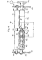
- the temporary obstructing means 64 in the illustrated embodiment is itself conventional. With reference to Figure 3 together with Figure 2, a pair of upstanding support walls 102 and 104 are disposed in spaced-apart relationship in the housing 2 ( Figure 1) in the front-rear direction (the direction perpendicular to the sheet surface in Figure 1).
- the temporary obstructing means 64 includes a driven shaft 106 and a follower shaft 108 extending across the pair of upstanding support walls 102 and 104.
- the driven shaft 106 is rotatably mounted on the upstanding support walls 102 and 104 via bearing members 110 and 112, and extends substantially horizontally. Two rollers 74 are fixed to the driven shaft 106 with some space between them in the axial direction.
- the driven rollers 74 can be made of suitable metallic or plastics material.
- One end portion of the driven shaft 106 projects beyond the upstanding support wall 104, and to this one end portion are mounted a rotatable sprocket wheel 114 and a conventional spring clutch 116 for selectively linking the sprocket wheel 114 and the driven shaft 106.
- the sprocket wheel 114 is drivingly connected to a driving source 118, which may be an electric motor, via a suitable connecting means (not shown). While the driving source 118 is energized, the sprocket wheel 114 is continuously rotated. When the clutch 116 is rendered operative, the sprocket wheel 114 is connected to the driven shaft 106.
- the follower shaft 108 is mounted on the upstanding support walls 102 and 104 so that it can rotate freely and move freely toward and away from the driven shaft 106.
- Two follower rollers 76 mentioned hereinabove are fixed to the follower shaft 108 correspondingly to the two driven rollers 74. If desired, instead of, or in addition to, mounting the follower shaft 108 rotatably, the follower rollers 76 may be mounted rotatably on the follower shaft 108.
- the follower rollers 65 can be made of suitable plastics or metallic material.
- Suitable spring members 130 and 132 are provided in relation to the bearing members 122 and 124 mounted on the follower shaft 108. These spring members 130 and 132 resiliently bias the follower shaft 108 toward the driven shaft 106 and thus press the follower rollers 76 against the driven rollers 74.
- the feed roller assembly 62 includes a driven shaft 134 and a follower shaft 136 extending across the pair of unstanding support walls 102 and 104.
- the driven shaft 134 is mounted rotatably on the upstanding support walls 102 and 104 via the bearings 138 and extends substantially horizontally.
- One end portion of the driven shaft 134 projects beyond the upstanding support wall 104, and a gear 143 is fixed to this one end portion.
- the gear 142 is drivingly connected to the driving source 118 through a suitable connecting means (not shown). Accordingly, while the driving source 118 is energized, the gear 142 and the driven shaft 134 to which it is fixed are continuously rotated in the direction of an arrow 144 ( Figure 2).
- the driven rollers 70 described above are mounted on the driven shaft 134. It is important that the driven rollers 70 include at least one positively driven roller and at least one non-positively driven roller.
- the driven rollers 70 include two centrally (axially inwardly) positioned positively driven rollers 70a and four non-positively driven rollers 70b.
- the positively driven rollers 70a and the non-positively driven rollers 70b are made of a comparatively light material, for example a plastics material such as polyactal resin.
- To the driven shaft 134 are fixed four axially spaced rings 146, 148, 150 and 152.
- One positively driven roller 70a and two non-positively driven rollers 70b are mounted between the rings 146 and 148.
- each of the non-positively driven rollers 70b has a larger inside diameter D 2 than the outside diameter d of the driven shaft 134, and is mounted'rotatably on the driven shaft 134.
- each of the positively driven rollers 70a is mounted on the driven shaft so as to be positively rotated in accordance with the rotation of the driven shaft 134.
- each of the positively driven rollers 70a is substantially the same as the outside diameter of the non-positively driven rollers 70b, but the inside diameter D l of each of the positively driven rollers 70a is larger than the outside diameter d of the driven shaft 134 and slightly larger than the inside diameter D 2 of each of the non-positively driven rollers 70b.
- the radial thickness of the positively driven rollers 70a is made slightly smaller than the radial thickness of the non-positively driven rollers 70b.
- Cooperatively acting means for transmitting the rotation of the driven shaft 134 positively to the positively driven rollers 70a are provided on the driven shaft 134 and the positively driven rollers 70a.
- those parts of the driven shaft 134 on which the positively driven rollers 70a are mounted have fixed thereto at least one pin 154 extending diametrically through the driven shaft 134 (in the drawing, two pins 154 spaced from each other axially of the driven shaft 134).
- the two ends of each pin 154 project beyond the outside surface of the driven shaft 134, and thus protruding portions 156 diametrically opposite each other (the two end portions 156 of the pin 154) exist on the outside surface of the driven shaft 134.
- Depressed portions 158 extending continuously in the axial direction are formed at two diametrically opposing parts of the inside surface of the positively driven roller 70a so that they correspond to the protruding portions 156.
- the end surface of the protruding portion 156 and the bottom surface of the depressed portion 158 both have a hemispherical sectional shape.
- Each of the protruding portions 156 is positioned within a respective one of the depressed portions 158.
- the difference between the length L between the bottom surface of the two depressed portions 158 diametrically opposed to each other and the length £ between the two protruding portions 156 diametrically opposed to each other, L-l, is made slightly smaller than the difference between the inside diameter D 1 of each positively driven roller.
- the positively driven rollers 70a are displaced gradually downwardly with respect to the driven shaft 134, and the height of the upper end of each positively driven roller 70a from the central axis of the driven shaft 134 decreases from h l to h 2 .
- the positively driven rollers 70a When the driven shaft 134 and the positively driven rollers 70a further rotate through 90 degrees from the angular position shown in Figure 6 in the direction of arrow 144, they again assume the angular position shown in Figure 5, and during this 90 degree rotation, the positively driven rollers 70a are displaced gradually upwardly with respect to the driven shaft 134, and the height of the upper end of each positively driven roller 70a from the central axis of the driven shaft 134 increases from h 2 to h l .
- the positively driven rollers 70a alternately ascend and descend twice every time the driven shaft 134 and the positively driven rollers 70 are rotated through one revolution (360 degrees).
- the protruding portions 156 and the depressed portions 158 are provided only at a single angular position so that every time the driven shaft 134 and the positively driven rollers 70a are rotated through one revolution, the positively driven rollers 70a ascend and descend once with respect to the driven shaft 134.
- three or more protruding portions 156 and depressed portions 158 may be provided at circumferentially spaced positions so that every time the driven shaft 134 and the positively driven rollers 70a are rotated through one revolution, the positively driven rollers 70a alternately ascend and descend three or more times.
- the non-positively driven rollers 70b are not substantially displaced upwardly and downwardly with respect to the driven shaft 134 and therefore, their heights, h, are substantially the same.
- the movement of the positively driven rollers 70a and the non-positively driven rollers 70b in the axial direction of the driven shaft 134 is restricted by the rings 146, 148, 150 and 152.
- the axial width X defined by the two positively driven rollers 70a located centrally (axially inwardly) is made smaller than the width of a sheet material having the narrowest width among those sheet materials which are delivered to the feed roller assembly 62. Accordingly, it is desirable that all sheet materials sent to the feed roller assembly 62 should, without fail, undergo not only the action of the positively driven rollers 70 but also the action of the non-positively driven rollers 70b.
- bearing members 160 and 162 are mounted on the opposite end portions of the follower shaft 136 located above the driven shaft 134.
- Elongated holes 164 and 166 extending perpendicularly to the driven shaft 134 are formed in the upstanding support walls 102 and 104, and the bearing members 160. and 162 are positioned in the holes 164 and 166.
- the follower shaft 136 is mounted on the upstanding support walls 102 and 104 so that it can be rotated freely and move freely toward and away from the driven shaft 134.
- the two follower rollers 72 are fixed to the follower shaft 136.
- One of the rollers 72 is positioned correspondingly to the three driven rollers 70a and 70b located between the rings 146 and 148.
- the other roller 72 is positioned correspondingly to the three driven rollers 70a and 70b located between the rings 150 and 152. If desired, instead of, or in addtion to, mounting the follower shaft 136 rotatably, the follower rollers 72 can be rotatably mounted on the follower shaft 136.
- the follower rollers 72 may be formed of a metallic or plastics material.
- the follower rollers 72 are pressed against the driven rollers 70 by their own weight and the weight of the follower shaft 136. If desired, it is possible to bias resiliently the follower shaft 136 toward the driven shaft 134 by a suitable spring member and thus press the follower rollers 72 against the driven rollers 70.
- the rotation of the driven shaft 134 being continuously rotated is transmitted to the positively driven rollers 70a via the protruding portions 156 and the depressed portions 158 and also to the non-positively driven rollers 70b through the frictional force FA.
- the positively driven rollers 70a and the non-positively driven rollers 70b are rotated in the direction of arrow 144.
- the sheet material S is thus fed in the direction of an arrow 168 mainly by the action of the non-positively driven rollers 70b, and the follower rollers 72 are rotated in the direction of an arrow 170.
- the positively driven rollers 70a alternately ascend and descend twice during one rotation, and when they have ascended to the highest position (the position shown in Figures 4 and 5), the height h l of the upper end of each positively driven roller 70a becomes substantially equal to the height, h, of the upper end of each non-positively driven roller 70b.
- the positively driven rollers 70a temporarily act on the sheet material S when they have ascended to the highest position (twice in one rotation).
- the sheet material S fed by the feed roller assembly 62 is passed between the guide plates 66 and 68 and conducted to. the nipping position between the driven rollers 74 (which are in an inoperative state) and the follower rollers 76. The leading edge of the sheet material S then abuts against the nipping position between the inoperative driven rollers 74 and the follower rollers 76. As a result, when the sheet material S has relatively high stiffness, the entire sheet material S is stopped, owing to its relatively high stiffness, as shown by the solid line in Figure 2 without substantial bending.
- the sheet material S has relatively low stiffness
- the sheet material S continues to be fed for some time by the action of the feed roller assembly 62 even after its forward movement has been obstructed by the temporary obstructing means 64.
- the sheet material S is bent between the temporary obstructing means 64 and the feed roller assembly 62 as shown by the two-dot chain line in Figure 2. Since, however, the distance t between the guide plates 66 and 68 is made sufficiently small, when the sheet material S is slightly bent, it contacts both the lower guide plate 66 and the upper guide plate 68. Consequently, further bending of the sheet material S is impeded, and the apparent stiffness of the sheet material S is increased. Accordingly, no undesirable creases are formed in the sheet material S and the whole of it is stopped.
- the positively driven rollers 70a are kept rotating because the rotation of the driven shaft 134 is positively transmitted to the positively driven rollers 70a by the co-operative action of the protruding portions 156 and the depressed portions 158.
- the positively driven rollers 70a act only temporarily on the sheet material S when they have ascended to the highest position (twice during one rotation), and therefore, a slipping condition is generated between the sheet material S at stoppage and the positively driven rollers 70a temporarily twice during one rotation of the positively driven rollers 70a. Accordingly, any soiling of the lower surface of the sheet material S by the rotation of the positively driven rollers 70a is only slight.
- the positively driven rollers 70a with the same structure as the non-positively driven rollers, or in other words to construct all of the driven rollers 70 as non-positively driven rollers, in order to circumvent sufficiently the soiling of the lower surface of the sheet material S.
- the experience of the present inventors suggests, however, that the following problems arise when all of the driven rollers 70 are adapted to be non-positively driven. Specifically, such a structure provides an insufficient action in causing the leading edge of the sheet material S to abut against the nipping position between the driven rollers 74 in the inoperative state and the follower rollers 76.
- any inclination of the sheet material S (when the leading edge of the sheet material S is not substantially perpendicular, but inclined, to the conveying direction 156) cannot be properly corrected.
- some delay tends to occur in conveying the sheet material S in the direction of arrow 168 by the driven rollers 74 and the follower rollers 76 (this delay produces an error in the synchronism of the rotation of the rotating drum 10 with the conveying of the sheet material S).
- the driven rollers 70 in the feed roller assembly 62 include positively driven rollers 70a
- the positively driven rollers 70a continue to rotate after the rotation of the non-positively driven rollers 70b has been stopped.
- the positibely driven rollers 70a intermittently (twice during one rotation) act on the sheet material S, and the above tendency can be fully circumvented.
- the clutch means 116 in the temporary obstructing means 64 is rendered operative in synchronism with the rotation of the rotating drum 10 ( Figure 1), and the driven rollers 74 begin to rotate in the direction of arrow 120.
- the conveying of'the sheet material S is resumed and it is conveyed in the direction of arrow 168.
- the follower rollers 76 are rotated in the direction of arrow 172.
- the temporary obstructing means 64 includes the driven rollers 74 which are to be selectively rotated and the follower rollers 76, and has lhe function of not only obstructing the forward movement of the sheet material S temporarily but also positively conveying it.
- the temporary obstructing means 64 When, for example, the temporary obstructing means 64 needs to have only the function of temporarily obstructing the forward movement of the sheet material S, it may be constructed in the form of a suitable stopping member which is adapted to be selectively held at an operating position at which it projects into the conveying path of the sheet material S and obstructs the forward movement of the sheet material S and at a non-operating position at which it moves away from the conveying path of the sheet material S and permits forward movement of the sheet material S.
- the sheet material conveying device 60 is provided in relation to the manual sheet material delivery device 40, and only the temporary obstructing means 64 in the sheet material conveying device 60 effectively acts on the automatic sheet material delivering means 38.
- the length of the conveying path of the sheet material from the automatic sheet material delivering means 3& to the temporary obstructing means 64 is relatively large and a feed means must be disposed between them, it is possible to use the same feed roller assembly as the feed roller assembly 62 as such a feed means and in relation to it, use a pair of the same guide plates as the plates 66 and 68.
- Figure 7 shows a modified example of the feed roller assembly 62.
- six positively driven rollers 70a and six non-positively driven rollers 70b are mounted on the drven shaft 134. More specifically, three positively driven rollers 70a having a relatively small axial width are mounted alternately with three non-positively driven rollers 70b between the rings 146 and 148. Likewise, between the rings 150 and 152, three positively driven rollers 70a having a relatively small axial dimension are mounted alternately with three non-positively driven rollers 70b.
- the structures and actions of the positively driven rollers 70a and the non-positively driven rollers 70b can be substantially the same as those of the positively driven rollers 70a and the non-positively driven rollers 70b shown in Figures 4 to 6.
- FIG 8 shows another modified example of the feed roller assembly 62.
- each of the two positively driven rollers 70a has an inside diameter D 1 substantially equal to the outside diameter d of the driven shaft 134, and each of the positively driven rollers 70a is fixed to the driven shaft 134 so as to rotate as a unit with the driven shaft 134.
- the radial thickness of each of the positively driven rollers 70a is substantially equal to the radial thickness of each of the non-positively driven rollers 70b.
- the outside diameter of. each of the positively driven rollers 70a is slightly smaller than the outside diameter of each non-positively driven roller 70b.
- each of the positively driven rollers 70a cannot be displaced upwardly and downwardly with respect to the driven shaft 134, and therefore, the height h 3 of the upper end of each positively driven roller 70a from the central axis of the driven shaft-134 does not change.
- the height h 3 is substantially equal to the height h of the upper end of each non-positively driven roller 70b from the central axis of the driven shaft 134.
- a plurality of positively driven rollers having a relatively small axial width may be arranged alternately with the non-positively driven rollers as shown, for example, in the modified example in Figure 7.
Landscapes
- Engineering & Computer Science (AREA)
- Mechanical Engineering (AREA)
- Delivering By Means Of Belts And Rollers (AREA)
Applications Claiming Priority (4)
| Application Number | Priority Date | Filing Date | Title |
|---|---|---|---|
| JP1984029973U JPS60142250U (ja) | 1984-02-29 | 1984-02-29 | シ−ト部材搬送装置 |
| JP29973/84 | 1984-02-29 | ||
| JP164871/84 | 1984-10-30 | ||
| JP1984164871U JPH0419000Y2 (fr) | 1984-10-30 | 1984-10-30 |
Publications (3)
| Publication Number | Publication Date |
|---|---|
| EP0153862A2 true EP0153862A2 (fr) | 1985-09-04 |
| EP0153862A3 EP0153862A3 (en) | 1987-09-09 |
| EP0153862B1 EP0153862B1 (fr) | 1989-02-01 |
Family
ID=26368225
Family Applications (1)
| Application Number | Title | Priority Date | Filing Date |
|---|---|---|---|
| EP85301351A Expired EP0153862B1 (fr) | 1984-02-29 | 1985-02-28 | Dispositif de transport de matériaux en feuilles |
Country Status (4)
| Country | Link |
|---|---|
| US (1) | US4678178A (fr) |
| EP (1) | EP0153862B1 (fr) |
| KR (1) | KR900007359B1 (fr) |
| DE (1) | DE3568028D1 (fr) |
Cited By (1)
| Publication number | Priority date | Publication date | Assignee | Title |
|---|---|---|---|---|
| FR2635766A1 (fr) * | 1988-08-30 | 1990-03-02 | Mutoh Ind Ltd | Mecanisme correcteur automatique de distribution en zig-zag de papier pour un appareil distributeur de papier |
Families Citing this family (22)
| Publication number | Priority date | Publication date | Assignee | Title |
|---|---|---|---|---|
| US5029840A (en) * | 1988-08-30 | 1991-07-09 | Ricoh Company, Ltd. | Automatic sheet feeder for an image recording apparatus |
| US4901820A (en) * | 1988-09-28 | 1990-02-20 | International Business Machines Corporation | Gold tab lubrication |
| US4875670A (en) * | 1988-11-17 | 1989-10-24 | Ncr Corporation | Floating idler wheel arm assembly for a document transport |
| US5049948A (en) * | 1988-12-22 | 1991-09-17 | Xerox Corporation | Copy sheet de-registration device |
| US4995615A (en) * | 1989-07-10 | 1991-02-26 | Cheng Kuan H | Method and apparatus for performing fair card play |
| US5054757A (en) * | 1990-03-12 | 1991-10-08 | Martin Samuel W | Mechanism and method for accumulating and folding sheets |
| JPH0455243A (ja) * | 1990-06-20 | 1992-02-21 | Canon Inc | シート材搬送装置 |
| DE4141530C2 (de) * | 1991-12-17 | 1993-09-30 | Ibm | Führung zur Übergabe von blattförmigen Medien |
| TW341955U (en) * | 1994-09-30 | 1998-10-01 | Mita Industrial Co Ltd | Device for conveying sheet members |
| US5605504A (en) * | 1995-04-28 | 1997-02-25 | Huang; Sming | Electronic wagering machine |
| US5653439A (en) * | 1996-01-11 | 1997-08-05 | Xerox Corporation | Exit tray corrugation slip rolls with a variable force idler |
| DE19650423A1 (de) * | 1996-12-05 | 1998-06-10 | Eastman Kodak Co | Vorrichtung zum Transportieren von blattförmigem Material |
| US6213458B1 (en) * | 1997-06-11 | 2001-04-10 | Konica Corporation | Document sheet feeding apparatus |
| HUP0102860A3 (en) * | 1998-07-31 | 2003-08-28 | Shuttleworth Inc Huntington | Low electrostatic discharge conveyor and method of its operation |
| US6812946B2 (en) * | 2001-06-06 | 2004-11-02 | Fuji Photo Film Co., Ltd. | Image forming device |
| JP4421879B2 (ja) * | 2003-11-20 | 2010-02-24 | 株式会社湯山製作所 | 薬包体搬送装置 |
| JP4061301B2 (ja) * | 2004-12-14 | 2008-03-19 | Tdk株式会社 | ヘッドサスペンションアセンブリ、回転検出機構および搬送機構 |
| JP4061302B2 (ja) * | 2004-12-14 | 2008-03-19 | Tdk株式会社 | 搬送機構 |
| US7322923B2 (en) * | 2005-06-17 | 2008-01-29 | Systec Corporation | Dunnage sheet removal apparatus |
| JP2008150198A (ja) * | 2006-12-20 | 2008-07-03 | Fuji Xerox Co Ltd | シート搬送用の従動回転体、シート搬送装置および画像形成装置 |
| IT1410807B1 (it) * | 2009-11-02 | 2014-09-25 | Prati Srl | Dispositivo di traino a rulli motorizzati per bande sovrapposte |
| US20110217407A1 (en) * | 2010-03-03 | 2011-09-08 | Ken Haines | Material sheet guiding system for a thermoforming machine |
Family Cites Families (7)
| Publication number | Priority date | Publication date | Assignee | Title |
|---|---|---|---|---|
| US1067805A (en) * | 1912-06-10 | 1913-07-22 | Samuel E Diescher | Feed mechanism. |
| GB1191169A (en) * | 1967-10-05 | 1970-05-06 | Timsons Ltd | Improved Sheet Feeding Mechanism |
| US4006815A (en) * | 1974-11-11 | 1977-02-08 | Alvey Inc. | Article transporting conveyor |
| JPS55155366A (en) * | 1979-05-24 | 1980-12-03 | Canon Inc | Copier having manual paper insertion mechanism |
| US4266660A (en) * | 1979-08-02 | 1981-05-12 | Smock Material Handling Company, Inc. | Accumulating-type powered roller conveyor |
| JPS5786849A (en) * | 1980-11-19 | 1982-05-31 | Canon Inc | Picture forming device having manual insertion mechanism |
| US4505381A (en) * | 1983-05-23 | 1985-03-19 | Harry Major Machine And Tool Co. | Conveyor roller |
-
1985
- 1985-02-26 US US06/705,804 patent/US4678178A/en not_active Expired - Fee Related
- 1985-02-28 EP EP85301351A patent/EP0153862B1/fr not_active Expired
- 1985-02-28 KR KR1019850001257A patent/KR900007359B1/ko not_active Expired
- 1985-02-28 DE DE8585301351T patent/DE3568028D1/de not_active Expired
Cited By (2)
| Publication number | Priority date | Publication date | Assignee | Title |
|---|---|---|---|---|
| FR2635766A1 (fr) * | 1988-08-30 | 1990-03-02 | Mutoh Ind Ltd | Mecanisme correcteur automatique de distribution en zig-zag de papier pour un appareil distributeur de papier |
| GB2224271A (en) * | 1988-08-30 | 1990-05-02 | Mutoh Ind Ltd | Alignment for paper feeding |
Also Published As
| Publication number | Publication date |
|---|---|
| KR850006620A (ko) | 1985-10-14 |
| DE3568028D1 (en) | 1989-03-09 |
| EP0153862A3 (en) | 1987-09-09 |
| US4678178A (en) | 1987-07-07 |
| EP0153862B1 (fr) | 1989-02-01 |
| KR900007359B1 (ko) | 1990-10-08 |
Similar Documents
| Publication | Publication Date | Title |
|---|---|---|
| EP0153862B1 (fr) | Dispositif de transport de matériaux en feuilles | |
| EP0195181B1 (fr) | Machine à copier électrostatique | |
| US4908668A (en) | Image-forming machine | |
| KR900008990B1 (ko) | 한번에 한장이상의 종이 공급방지 장치 | |
| US4621802A (en) | Sheet material conveying device | |
| US4965639A (en) | Toner supply cartridge for reproduction and printing machines | |
| JP2634431B2 (ja) | 複写機用の給紙装置 | |
| JP3581570B2 (ja) | 画像形成装置における廃トナー処理装置 | |
| US4540274A (en) | Image forming apparatus | |
| US4875077A (en) | Image-forming machine | |
| US4647183A (en) | Document-conveying copying machine | |
| JPH0211384Y2 (fr) | ||
| US4629307A (en) | Image forming apparatus with jammed paper access opening | |
| JPH0249244Y2 (fr) | ||
| EP0053035B1 (fr) | Appareil d'alimentation en feuilles | |
| JPS6242267B2 (fr) | ||
| JPH0326832B2 (fr) | ||
| JPS59214861A (ja) | 記録装置 | |
| JPS63244058A (ja) | 画像形成装置 | |
| GB2127384A (en) | Corner-registration by a pair of sensors spaced from a corner | |
| EP0026978B1 (fr) | Appareil de reproduction | |
| KR100202381B1 (ko) | 전자사진 프로세서의 기록용지 급지 장치 | |
| EP0351893B1 (fr) | Machine de formation d'images | |
| EP0351894A2 (fr) | Machine de formation d'images | |
| JPH07228372A (ja) | 給紙装置 |
Legal Events
| Date | Code | Title | Description |
|---|---|---|---|
| PUAI | Public reference made under article 153(3) epc to a published international application that has entered the european phase |
Free format text: ORIGINAL CODE: 0009012 |
|
| AK | Designated contracting states |
Designated state(s): DE FR GB NL |
|
| PUAL | Search report despatched |
Free format text: ORIGINAL CODE: 0009013 |
|
| AK | Designated contracting states |
Kind code of ref document: A3 Designated state(s): DE FR GB NL |
|
| 17P | Request for examination filed |
Effective date: 19871031 |
|
| 17Q | First examination report despatched |
Effective date: 19880610 |
|
| GRAA | (expected) grant |
Free format text: ORIGINAL CODE: 0009210 |
|
| AK | Designated contracting states |
Kind code of ref document: B1 Designated state(s): DE FR GB NL |
|
| REF | Corresponds to: |
Ref document number: 3568028 Country of ref document: DE Date of ref document: 19890309 |
|
| ET | Fr: translation filed | ||
| PLBE | No opposition filed within time limit |
Free format text: ORIGINAL CODE: 0009261 |
|
| STAA | Information on the status of an ep patent application or granted ep patent |
Free format text: STATUS: NO OPPOSITION FILED WITHIN TIME LIMIT |
|
| 26N | No opposition filed | ||
| PGFP | Annual fee paid to national office [announced via postgrant information from national office to epo] |
Ref country code: FR Payment date: 19950210 Year of fee payment: 11 |
|
| PGFP | Annual fee paid to national office [announced via postgrant information from national office to epo] |
Ref country code: GB Payment date: 19950220 Year of fee payment: 11 |
|
| PGFP | Annual fee paid to national office [announced via postgrant information from national office to epo] |
Ref country code: DE Payment date: 19950222 Year of fee payment: 11 |
|
| PGFP | Annual fee paid to national office [announced via postgrant information from national office to epo] |
Ref country code: NL Payment date: 19950228 Year of fee payment: 11 |
|
| PG25 | Lapsed in a contracting state [announced via postgrant information from national office to epo] |
Ref country code: GB Effective date: 19960228 |
|
| PG25 | Lapsed in a contracting state [announced via postgrant information from national office to epo] |
Ref country code: NL Effective date: 19960901 |
|
| GBPC | Gb: european patent ceased through non-payment of renewal fee |
Effective date: 19960228 |
|
| PG25 | Lapsed in a contracting state [announced via postgrant information from national office to epo] |
Ref country code: FR Effective date: 19961031 |
|
| NLV4 | Nl: lapsed or anulled due to non-payment of the annual fee |
Effective date: 19960901 |
|
| PG25 | Lapsed in a contracting state [announced via postgrant information from national office to epo] |
Ref country code: DE Effective date: 19961101 |
|
| REG | Reference to a national code |
Ref country code: FR Ref legal event code: ST |