EP0155664A2 - Verfahren und System zur PCM-Aufnahme/Wiedergabe mit rotierendem Kopf - Google Patents
Verfahren und System zur PCM-Aufnahme/Wiedergabe mit rotierendem Kopf Download PDFInfo
- Publication number
- EP0155664A2 EP0155664A2 EP85103110A EP85103110A EP0155664A2 EP 0155664 A2 EP0155664 A2 EP 0155664A2 EP 85103110 A EP85103110 A EP 85103110A EP 85103110 A EP85103110 A EP 85103110A EP 0155664 A2 EP0155664 A2 EP 0155664A2
- Authority
- EP
- European Patent Office
- Prior art keywords
- data
- signal
- recording
- recorded
- reproduced
- Prior art date
- Legal status (The legal status is an assumption and is not a legal conclusion. Google has not performed a legal analysis and makes no representation as to the accuracy of the status listed.)
- Granted
Links
Images


Classifications
-
- G—PHYSICS
- G11—INFORMATION STORAGE
- G11B—INFORMATION STORAGE BASED ON RELATIVE MOVEMENT BETWEEN RECORD CARRIER AND TRANSDUCER
- G11B5/00—Recording by magnetisation or demagnetisation of a record carrier; Reproducing by magnetic means; Record carriers therefor
- G11B5/02—Recording, reproducing, or erasing methods; Read, write or erase circuits therefor
- G11B5/09—Digital recording
-
- G—PHYSICS
- G11—INFORMATION STORAGE
- G11B—INFORMATION STORAGE BASED ON RELATIVE MOVEMENT BETWEEN RECORD CARRIER AND TRANSDUCER
- G11B20/00—Signal processing not specific to the method of recording or reproducing; Circuits therefor
- G11B20/10—Digital recording or reproducing
- G11B20/18—Error detection or correction; Testing, e.g. of drop-outs
- G11B20/1806—Pulse code modulation systems for audio signals
- G11B20/1809—Pulse code modulation systems for audio signals by interleaving
-
- G—PHYSICS
- G11—INFORMATION STORAGE
- G11B—INFORMATION STORAGE BASED ON RELATIVE MOVEMENT BETWEEN RECORD CARRIER AND TRANSDUCER
- G11B20/00—Signal processing not specific to the method of recording or reproducing; Circuits therefor
- G11B20/10—Digital recording or reproducing
- G11B20/10527—Audio or video recording; Data buffering arrangements
Definitions
- the present invention relates to rotary head type PCM recording/reproduction. More particularly, the invention concerns a rotary head type PCM recording/ reproduction method and system suited for concealment and correction of such data errors or defects as produced by drop-outs of the recording medium such as magnetic tape and jamming of head gap.
- the amount of data which can be recorded on a recording medium per unit area is increased by a factor of about 10(ten) when compared with other system such as e.g. a stationary head type multi-track PCM recorder.
- the R-DAT recorder for which two heads are generally sufficient is more advantageous in respect to the manufacturing cost and reliability than the stationary head type multi-track PCM recorder which usually requires 10 to 20 heads.
- Fig. 1 graphically illustrates two-channel stereophonic signals and sampling points.
- the left-channel signal (represented by L) and the right-channel signal (represented by R) are sampled alternatively on the time-sequential basis in the order of L 0 ⁇ R 0 ⁇ L 1 ⁇ R 1 ⁇ L 2 ⁇ R 2 and so on.
- the two-channel signals are multiplexed on the time division basis to be transmitted as a serial signal.
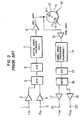
- a reference numeral 1 denotes a left-channel signal input terminal
- 2 denotes a right-channel signal input terminal
- 3 denotes a left-channel input amplifier
- 4 denotes a right-channel input amplifier
- 5 denotes a multiplexer (MPX) for alternately changing over the channels to be recorded
- 6 denotes an analog-to-digital (A/D) converter
- 7 denotes a digital signal processing circuit for the recording signal
- 8 denotes a recording output amplifier
- 9 denotes a rotatable head cylinder
- 10 denotes a magnetic head for a first channel (referred to also as "ch-1 head")
- 11 denotes a magnetic head for a second channel (referred to also as "ch-2 head”)
- 12 denotes a magnetic tape
- 13 denotes a reproducing preamplifier
- 14 denotes a signal processing circuit for reproduced signal
- 15 denotes a digital signal processing circuit for reproduced signal
- 15 denotes
- the audio signals of left-channel and right-channel are adjusted in level by the respective input amplifers 3 and 4 to be subsequently subjected to the channel multiplexing by the MPX 5 in the sequential order of L, R, L, R as shown in Fig. 1.
- the analog signal outputted from the MPX 5 is converted into a digital signal by the A/D converter 6 to be supplied to the digital signal processing circuit 7 where two basic processings are performed as mentioned below.
- the data transmitted thereto on the time serial basis are once stored in a memory such as RAM incorporated in the processing circuit, which data are then read-out from the memory in the sequence differing from the order in which the data have been written.
- This operation is referred to as the interleaving operation which is a sort of data dispersing processing for allowing the correct original signal to be restored even when the data as reproduced suffer drop-outs or errors in the block.
- This interleaving processing is carried out by a data delay/rearraying circuit which is referred to as the interleaver.
- the interleaved signal is so arrayed as to constitute error detection and correction blocks each of which is then added with a code signal for error detection and correction such as Reed-Solomon code.
- the signal processed as mentioned above is recorded on the magnetic tape 12 by the pair of rotary magnetic heads 10 and 11 after having been amplified through the recording amplifier 8.
- the signal picked up from the magnetic tape 12 by means of the magnetic heads 10 and 11 is amplified by the reproduction preamplifier 13 and undergoes, if necessary, correction of waveform referred to as the waveform equalization, to be subsequently supplied to the digital signal processing circuit 14 of the reproduction system, where the input data are arrayed so as to constitute the data detection/correction blocks, the data suffering errors are detected to be corrected (or concealed) and the sequence of the interleaved data is transformed to the original time-series sequence with the aid of a deinterleaver. This processing is referred to as the deinterleaving operation.
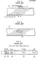
- Fig. 3 shows a record pattern produced on a magnetic tape by the rotary head type PCM recorder, as viewed in the direction perpendicularly to the plane of the magnetic tape.-
- a reference numeral 21 denotes tracks recorded by the magnetic head 10 for the first channel ch-1
- 22 denotes tracks recorded by the magnetic head 11 for the second channel ch-2.
- Fig. 4 shows a magnetic tape whose magnetic surface suffers a defect due to injury or deposition of dust particles. More specifically, a numeral 23 denotes a defect of record produced due to deposition of dust or magnetic particles scaled off from the tape.
- Fig. 5 of the accompanying drawings shows a typical one of the hitherto known record formats in which data are recorded in a block array through the interleaving procedure which is effective for error correction, as elucidated above. More specifically, Fig. 5 shows the record format of a capacity which can be recorded and/or reproduced through a single scan by a single head. This capacity will be referred to as one field. As will be seen in Fig.
- one field is composed of 256 blocks each of which is subdivided in the manner illustrated in Fig. 6.
- Fig. 6 For particulars, reference may be made to Kentaro Odaka's article "A Rotary Head High Density Audio Tape Recorder” of "Technical Report Of Japan Electronic Communication Association", Vol. 1. 82, No. 190, EA 82-46 51, Nov. 30, 1982. Referring to Fig.
- a numeral 24 designates a synchronizing signal SYNC (consisting of eight bits)
- 25 designates any identify code and block address code (consisting of 16 bits)
- 26 denotes a parity check code for data (consisting of 32 bits)
- 27 designates audio signal data (of 96 bits)
- 28 designates a cyclic redundancy check (CRC) code (of 16 bits) for the error check.
- the parity code 26 is constituted by two parity words referred to as P parity and Q parity each of 16 bits.
- data 27 is composed of six words W 0 , W 1 , W 2 , W 3 , W 4 and W 5 each of 16 bits.
- one block is constituted by 168 bits in total, and 256 blocks in turn constitute one field.
- a format of interleaving will be described. It will be seen that any given block includes these words which are dispersed with a distance corresponding to 128 words. In other words, any two adjacent data words in a given block are chronographically distanced from each other for a time corresponding to 128 sampling points.
- even-numbered data such as L 0 , R - , L 2 , R 2 and so forth (referred to also as even data) and the odd-numbered data such as L l' R 1' L3 R 3 and so forth (also referred to as odd data) are grouped in a left half and a right half, respectively, of one field, as viewed in Fig. 5.
- the original analogue signal can be nevertheless reproduced approximately in the original form through concealment procedure based on the previous value holding method or mean value interpolation method, so far as either the even data or odd data can be reproduced.
- the error concealment length corresponds to 128 blocks.
- the error correction or error concealment can be accomplished with a relatively high efficiency for the error produced due to the drop-out of the magnetic tape or deposition of dusts thereon.
- the signal format of this type which is so arranged that the processing of all data contained in one format can be completed within a single scan period of one magnetic head will be referred to as the single-scan-completion type format or the single-field-completion type format. It should be however pointed out that the hitherto known format of the single-field-completion type suffers serious disadvantages in case the magnetic gap of one of the paired magnetic heads is jammed through deposition of dust or magnetic particles scaled off from the tape.
- An object of the present invention is to provide a recording method for a rotary head type PCM recorder capable of realizing a data array (format) for audio data recorded on a magnetic tape which format allows the audio data to be reproduced with an improved fidelity even when the drop-out of tape takes place.
- Another object of the present invention is to provide a reproducing method and apparatus for a rotary head type PCM recorder which makes it possible to derive a reproduced analogue signal with an adequate sound quality for practical applications even when no signal is produced by one of the magnetic heads due.to the jamming of the magnetic gap thereof.
- the odd-numbered data (or odd data) is recorded and reproduced by one head provided for one channel
- the even-number data (even data) is recorded and reproduced by the other magnetic head for other channel or alternatively the odd data and the even data are recorded and reproduced in a preceding half and a succeeding half, respectively, of each track scan for two channels, wherein data is so formatted as to be completed in two fields (i.e. in two tracks), while the code for error detection and correction is so arrayed as to be completed on the single-field (single-track) basis.
- data is completed through the scan by the two heads. Accordingly, even when there should arise such a situation in which no output signal is produced by one of the heads at all, it is possible to reproduce at least approximately the original analogue signal on the basis of the output signal from the other head by making use of the average value interpolation or the like method. Besides, even when error as occurred is concentrated to a certain region of the recording medium due to the drop-out of the tape or damage of the tape edge, it is possible to evade such situation that degradation of the sound quality is concentrated or confined to a particular channel.
- Fig. 7 is a view for illustrating a recording/ reproducing method for a rotary head PCM recorder according to an exemplary embodiment of the invention.
- a reference numeral 24 designates skew tracks on which only the sampled data i.e. data words (referred to as odd data) that correspond to the odd-numbered sampling points are recorded
- 25 designates skew tracks on which only the sampled data (referred to as even data) corresponding to the even-numbered sampling points are recorded.
- the odd data are recorded on the tracks allocated to the magnetic head for a first channel ch-1 with the even data being recorded on the tracks allocated to the magnetic head for a second channel ch-2.
- the left channel data L is recorded in a preceding half of a given single scan (single field) of each head while the right channel data R is recorded in the succeeding half of the scan.
- the right channel data R is recorded in the preceding half, which is followed by the succeeding half in which the left channel data L is recorded.
- Fig. 9 shows an example of the data recording format which can be adopted in carrying out the recording/reproducing method according to the invention.
- a reference letter 29A designates one field containing only the odd data
- 29B designates another one field containing only the odd data. More specifically, the data in the one field 29A are recorded on one of the tracks.24 shown in Fig. 7 while the data in the other single field 29B are recorded on one of the tracks 25.
- one data block is constituted by units referred to as the symbols each of several bits.
- an identify code signal IDENTIFY of three symbols
- C2-PARITY making use of Reed-Solomon code
- Cl-PARITY of 2 symbols
- one block consists of 36 symbols or 288 bits in total.
- one field is composed of 128 blocks of which the first 48 blocks and the last 48 blocks (hence 96 blocks in total) are allocated for the recording of data signal, while 32 intermediate blocks are allotted for recording the parity signal C2-PARITY.
- the odd data of left channel L-ch (or right channel) is arrayed in the first 48 blocks of one field 29A, while the odd data of right channel R-ch (or left channel) is located in the last 48 blocks.
- the even data of right channel R-ch (or left channel L-ch) are recorded in the first 48 blocks while the even data of left channel L-ch (or right channel R-ch) are located in the last 48 blocks.
- the error detection and correction code should desirably be completed for each track, i.e. within one field.
- the error detection/correction signal which is created through arithmetic processing of the data signal should be completed within one field. This is because the data of one field has to be correctly reconstituted within the one field, even when either head ch-1 or ch-2 should fail to produce the output, so long as the other head produces the data signal as well as the parity signal.
- the data format shown in Fig. 9 is prepared to meet the above requirement, wherein Reed-Solomon code is made use of as the error detection/ correction code.
- the data word of 24 symbols is encoded by using (32, 24) Reed-Solomon codes.
- the symbols constituting the C2-parity code block are interleaved, and the data word or C2-parity word of 30 symbols constituting one block is encoded by using (32, 20) Reed-Solomon code. Consequently, the pair of parity signals Cl-PARITY and C2-PARITY are formed in the fields 29A and 29B independently, which means that the code structure is completed in each field.
- the format has to be so prepared that the digital dubbing of data derived through the sampling at the frequencies of 48 KHz and 32 KHz (as used in the direct satellite broadcasting or DBS) and 44.1 KHz (used in the compact disk system) can be effected.
- the recording of data sampled at the frequencies of 48 KHz and 32 KHz is carried out by varying correspondingly the transportation speed of the tape.
- a format for recording data sampled at 48 KHz is used in common.
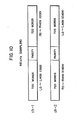
- Fig. 10 shows allocation of data resulting from the sampling at 48 KHz to the field assigned to the heads ch-1 and ch-2, respectively. More specifically, 2880 words in total inclusive of 1440 words for the left and right channel data, respectively, are allocated to two fields. In the field assigned to the head ch-1, there are recorded the odd data of 720 words out of 1440 words constituting the left channel data and the odd data of 720 words out of the 1440 words constituting the right channel data, while the remaining even data of the right and left channels are recorded in the field assigned to the magnetic head ch-2.
- Fig. 11 shows the format thus prepared, wherein the locations at which 2646 words of data words 0 to 2645 are recorded are illustrated.
- the field assigned to the head ch-1 is assumed to record only the odd data with the field assigned to the head ch-2 recording only the even data. It will however be understood that the change in the number of data words derived through the sampling at the frequency of 44.1 KHz can be dealt with by changing over the number of words to be processed between 661 and 662.
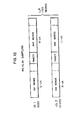
- Fig. 12 shows a recording format prepared for the data sampled at the frequency of 44.1 KHz according to another embodiment of the invention.
- this format it is assumed that the head ch-1 is used for recording the odd data with the head ch-2 being employed for the recording the even data, wherein 661 words of the left-channel data is recorded in the field for the head ch-l with 662 words of the same channel being recorded in the field ch-2, while 662 words of the right-channel data is recorded in the field assigned to the head ch-1 with the 661 words of the same channel being recorded in the field for the head ch-2.
- 1323 words (sampled data) for the left and right channels, respectively, are obtained as the complete data through two scans by the heads ch-1 and ch-2.
- Fig. 13 shows a modification of the recording pattern shown in Fig. 8 which is rendered more immune to error due to the drop-out of the tape. More specifically, in the format shown in Fig. 8 in which the left channel data and the right channel data are alternately recorded in the preceding (earlier) and succeeding (later) halves, respectively, of the track as observed in the head scan direction of the track row, the format shown in Fig. 13 is so modified that the odd data and the even data-are recorded, being allocated to the preceding and succeeding halves, respectively, of each scan of the head. Consequently, in the playback operation, the complete data can be retrieved from the paired adjacent tracks.
- the tracks (a) and (b) are scanned to read-out sequentially the right-channel odd data, the left-channel even data, the left-channel odd data and the right-channel even data, which are subsequently stored at the memory locations described below. Then, by controlling the sequence in which these data are read-out from the memory, the audio data arrays for the left channel and the right channel are reconstituted, to thereby reproduce the original stereophonic audio signals. Since in the rotary head type PCM recorder, data are recorded with different azimuth angles on any adjacent tracks, as is well known in the art, the paired track can be easily identified. Of course, it is possible to allocate the preceding half of a single head scan to the recording of the even data with the succeeding half being allocated to the recording of the odd data.
- Figs. 14A and 14B are views illustrating an example of the data recording format which can be employed in carrying out the recording/reproducing method in accordance with the modified recording pattern shown in Fig. 13. More particularly, there are shown in Figs. 14A and 14B the contents of the paired fields 29A' and 29B' having recorded therein the odd data and the even data, respectively. The data of the first one 29A' of the paired fields are recorded on the track (a) shown in Fig. 13, while the data of the second field 29B' are recorded on the track (b). With the format illustrated in Figs. 14A and 14B, the data blocks described hereinbefore in conjunction with Fig. 9 are formed.
- L and R in Figs. 14A and 14B represent the left- and right-channel signals
- the affixed numerals represent the sampling sequence
- the affixed letters u and i represent the more significant and less significant bits or symbols.
- Letters P and Q represents the Reed-Solomon codes Cl-PARITY and C2-PARITY, respectively.
- the sampled time-serial signals L and R are in the state undergone the processing for forming the error detection and correction signal as well as the interleaving processing described hereinbefore in conjunction with the format shown in Fig. 9.
- parity symbols are defined so as to satisfy the following equations: where H Q and Hp represent parity matrixes given by and The calculation is defined on GF(2 8 ) by the following polynomial. and a primitive element a in GF (28) is defined as follows.
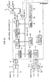
- Fig. 15 shows in a schmatic block diagram a general arrangement of the rotary head type PCM recording/ reproducing apparatus according to an embodiment of the invention.
- a left-channel analog input signal and a right-channel analog signal applied to input terminals 1 and 2 are selected by a multiplexer or MPX 5 to be converted alternately to digital signal of 16 bits by an analog-to-digital (D/A) converter 6.
- the digital signal of 16 bits is then divided into a signal of eight more significant bits (MSB) and a signal of eight less significant bits (LSB) through a 16-to-8 bit conversion circuit 31, which signals are then alternately outputted onto a 8-bit bus line 30.
- the signal of eight MSBs and the signal of eight LSBs produced on the bus-line 30 are sequentially stored in a memory 32 at predetermined locations or regions.
- the signals stored in the memory are encoded by an error correcting code encoder/decoder (ECU) 33 and subsequently read out in a predetermined sequence to be modulated by a modulating circuit 34, the output signal of which is amplified by a recording amplifier 8 and recorded on a magnetic tape 12 through magnetic heads 10 and 11.
- ECU error correcting code encoder/decoder
- the magnetic heads 10 and 11 are changed over to the reproducing mode from the recording mode by a changing-over switch (not shown).
- the reproduced signal outputted from the heads is amplified by a preamplifier 13 and subjected to predetermined waveform equalizing processing through a waveform equalizer 35.
- the signal is demodulated by a demodulator circuit 37 to be produced onto the bus line 30.
- the reproduced and demodulated signals on the bus line 30 are sequentially stored in the memory 32 at predetermined locations or regions.
- the signals stored in the memory are decoded by the error correcting code encoder/decoder 33 and subsequently read out in a predetermined sequence.
- the signals of eight MSBs and eight LSBs as read out are converted into the original digital signal of 16 bits by a 8-to-16 bit conversion circuit 39.
- the 16-bit signal is converted to an analog signal through a digital-to-analog (D/A) converter 15 to be divided into the right-channel signal and the left-channel signal.
- D/A digital-to-analog
- the output signal of the D/A converter may be sampled and held by sample and hold circuits 17 and 18 alternately to be supplied to audio output terminals 19 and 20 as the left-channel and right-channel signals.
- the memory 33 is constituted by four storage regions M a , Mb, M c and M d , as shown in Fig. 16. These regions are dealt with on the basis of the paired regions M a : M b and M c : M d .
- the sampled signal data of left and right (L-ch, R-ch) channels are so recorded that the odd data and the even data are located at the respective allocated regions as shown in Fig. 16.
- the memory is divided into four regions each of which is then divided into three subregions.
- data is divided to be stored in two paired regions M a : Mb and M c : Md, where the memory regions M a and M c on one hand and M b and M d on the other hand are of the identical structure.
- regions M a and M b the even data and the odd data of the left and right channels, respectively, for a predetermined period.
- the even data of the left channel is recorded in the region M a with the odd data of the same channel being recorded in the region M b
- the odd data of the right channel is stored at the region M a with the even data of the same channel being . stored at the region M b .
- the even data of the left channel is stored at the preceding (upper) half area of the region M a with the odd data of the same channel being stored at the succeeding (lower) half area of the region M b .
- the odd data of the right channel is stored at the succeeding half area of the region M a with the even data of the same channel being stored at the preceding half area of the region M b .
- the parity code is stored at the respective intermediate area.
- the operation mentioned above is controlled by a memory control circuit 38 on the basis of address signal. Namely, in dependence on the results of discrimination as to whether the data is of right or left channel and whether the data is odd or even, the regions at which the data are to be recorded are controlled by using the address signals.
- the encoding operation for error detection and correction described above is executed for each regions M a and M b .
- the encoded data stored at the regions M c and M b are recorded on the magnetic tape 12.
- the encoding operation and the recording operation are performed alternately.
- the reproduced signal data are fetched by the memory 32 for reproduction at the regions M a , M b , M c and M d in this order.
- the data thus fetched are decoded by the ECU 33 in the sequence in which they have been fetched.
- the decoded data are sequentially read out as the left channel data and the right channel data from the pair of regions M a and M b and the pair of regions M c and M d , respectively.
- the memory for the recording operation and the memory for the reproducing operation are constituted by the same memory. It is however possible to provide two memories one of which is constituted by the memory regions M a and M b with the other memory being constituted by the regions M c and M d .
- the memory regions M a and M b are selected.
- the odd and even data samples of the left and right channels are fetched to be loaded at predetermined regions or areas of the memory (M a , M b ).
- the encoding period from t 4 to t 5 data located in the memory region M a are encoded.
- the encoded data of the memory region M a is recorded on the magnetic tape in the predetermined format during a recording period (54).
- the encoded data of the memory region M b is recorded on the magnetic tape in the predetermined format.
- the memory regions M c and M d are selected. Subsequently, data are fetched, encoded and recorded on the magnetic tape in the similar manner.
- a data reproducing period (55) from t 1 to t 5 the reproduced data is loaded in the memory region M a as in the case of the data fetching period (56).
- a decoding period (57) from t 2 to t 31 the data is decoded.
- the reproduced data is loaded in the memory region M b .
- the decoding period (57) from t 4 to t5 the data is decoded.
- an output period (58) from t 5 to t 9 the decoded data of the memory regions M a and M b are sequentially outputted on the time-serial basis.
- the reproduced data are stored, decoded and outputted sequentially on the time-series basis.
- Fig. 18 is a view showing a switch circuit for illustrating a method of controlling the read/write operations to and from the memory 32, by way of example.
- a switch SW-1 is closed to the memories M a and M b while a switch SW-10 is closed to the memories M c and M d during a period from t 0 to t 5 .
- switches SW-2 and SW-3 select the memories M a or M b in dependence on the result of identification of the data supplied to the memory input terminal M IN as to the left or right channel and odd or even data.
- a switch SW-8 is closed to decode the data of the memory region M c , the decoded data being outputted during a succeeding period from t 1 to t 2 .
- a switch SW-9 is closed to decode the data located at the memory region M d , the decoded data being outputted during a succeeding period from t 3 to t 4 .
- the data outputted through the switches SW-8 and SW-9 are transferred to the memory output terminal M OUT by way of the switch SW-10 closed to the memory (M a , M b ) during a period from t 0 to t 4 .
- the reproduced signal is inputted to the memory input terminal MIN, while the memory output signal is outputted from the memory output terminal M OUT .
- the switch SW-1 is closed to the memories M a and Mb.
- the switch SW-2 is closed to the memory M a , whereby the reproduced signal is stored in the memory M a .
- the signal placed in the memory M a is decoded.
- the switch SW-3 is closed to the memory M b , whereby the reproduced signal is stored in the memory M b .
- the signal located in the memory M b is decoded. Subsequently, during a period from t 5 to t 9 , the switch SW-10 is closed to the memories M a and M b , while the switches SW-6 and SW-7 are alternately closed, resulting in that the signals stored in the memories M a and M b are outputted sequentially on the time-series basis.
Landscapes
- Engineering & Computer Science (AREA)
- Multimedia (AREA)
- Signal Processing (AREA)
- Signal Processing For Digital Recording And Reproducing (AREA)
- Digital Magnetic Recording (AREA)
Applications Claiming Priority (2)
| Application Number | Priority Date | Filing Date | Title |
|---|---|---|---|
| JP50915/84 | 1984-03-19 | ||
| JP59050915A JPH07122966B2 (ja) | 1984-03-19 | 1984-03-19 | 回転ヘッド型pcmレコーダの記録方法及び再生方法 |
Publications (4)
| Publication Number | Publication Date |
|---|---|
| EP0155664A2 true EP0155664A2 (de) | 1985-09-25 |
| EP0155664A3 EP0155664A3 (en) | 1986-05-28 |
| EP0155664B1 EP0155664B1 (de) | 1990-06-13 |
| EP0155664B2 EP0155664B2 (de) | 1996-04-10 |
Family
ID=12872076
Family Applications (1)
| Application Number | Title | Priority Date | Filing Date |
|---|---|---|---|
| EP85103110A Expired - Lifetime EP0155664B2 (de) | 1984-03-19 | 1985-03-18 | Verfahren und System zur PCM-Aufnahme/Wiedergabe mit rotierendem Kopf |
Country Status (5)
| Country | Link |
|---|---|
| US (1) | US4685004A (de) |
| EP (1) | EP0155664B2 (de) |
| JP (1) | JPH07122966B2 (de) |
| KR (1) | KR890004752B1 (de) |
| DE (1) | DE3578249D1 (de) |
Cited By (10)
| Publication number | Priority date | Publication date | Assignee | Title |
|---|---|---|---|---|
| EP0197560A3 (en) * | 1985-04-10 | 1987-08-19 | Hitachi, Ltd. | Method and apparatus for recording and/or reproducing pcm signals |
| EP0178589A3 (en) * | 1984-10-17 | 1988-02-17 | Hitachi, Ltd. | Method and apparatus for recording pcm signal |
| DE3733242A1 (de) * | 1986-10-02 | 1988-04-14 | Victor Company Of Japan | Korrekturschaltung fuer codefehler |
| EP0222386A3 (en) * | 1985-11-13 | 1989-01-25 | Hitachi, Ltd. | Method and apparatus for pcm recording and reproducing audio signal |
| EP0235782A3 (en) * | 1986-03-04 | 1989-02-22 | Sony Corporation | Apparatus for reproducing a digital signal |
| US4853797A (en) * | 1987-02-26 | 1989-08-01 | Sony Corporation | Fir type digital filter for recording and reproducing apparatus |
| EP0364229A3 (de) * | 1988-10-14 | 1991-09-18 | Sony Corporation | Datenaufzeichnungsverfahren und -vorrichtung |
| EP0449212A3 (en) * | 1990-03-27 | 1992-12-09 | Sanyo Electric Co., Ltd. | Signal processing circuit of digital audio tape recorder |
| EP0449213A3 (en) * | 1990-03-27 | 1993-06-16 | Sanyo Electric Co., Ltd. | Interleave address generating circuit of digital audio tape recorder |
| CN106813688A (zh) * | 2013-10-28 | 2017-06-09 | 日本电产三协株式会社 | 数据检测装置 |
Families Citing this family (23)
| Publication number | Priority date | Publication date | Assignee | Title |
|---|---|---|---|---|
| US4675754A (en) * | 1984-02-21 | 1987-06-23 | Mitsubishi Denki Kabushiki Kaisha | Magnetic recorder/reproducer |
| JPS6253522A (ja) * | 1985-09-03 | 1987-03-09 | Sony Corp | Pcm信号の記録再生方法 |
| US4807055A (en) * | 1985-09-11 | 1989-02-21 | Pioneer Electronic Corporation | Multi-speed magnetic recording playback |
| JPS6390075A (ja) * | 1986-10-02 | 1988-04-20 | Victor Co Of Japan Ltd | デイジタル信号復調装置 |
| JPS63187469A (ja) * | 1987-01-30 | 1988-08-03 | Hitachi Ltd | 回転ヘツド形記録再生装置 |
| US5237461A (en) * | 1987-06-03 | 1993-08-17 | Robert Bosch Gmbh | Method and apparatus for reproducing video data stored on a magnetic tape in a manner facilitating search and slow-motion operation |
| US4943964A (en) * | 1987-08-12 | 1990-07-24 | Hitachi, Ltd. | PCM signal reproducing device |
| US5031218A (en) * | 1988-03-30 | 1991-07-09 | International Business Machines Corporation | Redundant message processing and storage |
| JPH0211053A (ja) * | 1988-03-30 | 1990-01-16 | Internatl Business Mach Corp <Ibm> | メッセージ処理方法 |
| GB2258751B (en) * | 1988-06-07 | 1993-04-28 | Mitsubishi Electric Corp | Digital signal recording method a digital video tape recorder and a recorded tape |
| GB2220521B (en) * | 1988-06-07 | 1993-04-28 | Mitsubishi Electric Corp | Digital signal recording method a digital video tape recorder and a recorded tape |
| JP2553668B2 (ja) * | 1988-10-13 | 1996-11-13 | 松下電器産業株式会社 | 磁気記録方法 |
| JPH0242686A (ja) * | 1989-03-27 | 1990-02-13 | Mitsubishi Electric Corp | 回転ヘッド形磁気記録・再生装置 |
| US5239422A (en) * | 1989-04-28 | 1993-08-24 | Pioneer Electronic Corporation | Rotary head type digital magnetic recording-reproducing apparatus |
| EP0397472B1 (de) * | 1989-05-12 | 1995-11-29 | Mitsubishi Denki Kabushiki Kaisha | Verfahren und Aufzeichnungs- und Wiedergabegerät mit einem rotierenden Kopf |
| JPH04286774A (ja) * | 1991-03-18 | 1992-10-12 | Hitachi Ltd | Pcm信号記録方式 |
| JPH05181209A (ja) * | 1991-09-20 | 1993-07-23 | Fuji Photo Film Co Ltd | 情報記録読取方法及び装置 |
| JPH06195884A (ja) * | 1992-10-30 | 1994-07-15 | Sony Corp | 磁気記録再生装置 |
| US5715358A (en) * | 1993-06-22 | 1998-02-03 | Sanyo Electric Co., Ltd. | Method for recording at least two picture signals and method of reproduction at least two picture signals |
| US5499147A (en) * | 1993-12-02 | 1996-03-12 | Industrial Technology Research Institute | Rotary head recording and reproduction apparatus with memory and method of operation which compares a reproduced signal with an original signal |
| JPH087208A (ja) * | 1994-06-22 | 1996-01-12 | Sony Corp | 磁気テープ記録再生装置 |
| US5860060A (en) * | 1997-05-02 | 1999-01-12 | Texas Instruments Incorporated | Method for left/right channel self-alignment |
| JP2000353364A (ja) * | 1999-06-10 | 2000-12-19 | Sony Corp | データ記録媒体、記録装置及び方法、並びに再生装置及び方法 |
Family Cites Families (6)
| Publication number | Priority date | Publication date | Assignee | Title |
|---|---|---|---|---|
| JPS53142208A (en) * | 1977-05-18 | 1978-12-11 | Teac Corp | Method of recording pcm signal |
| GB2073935B (en) * | 1980-04-11 | 1983-12-21 | Rca Corp | Tape format to facilitate error concealment and apparatus for recording and/or replaying same |
| JPS57132486A (en) * | 1981-02-10 | 1982-08-16 | Sony Corp | Magnetic recorder and reproducer |
| JPS59177706A (ja) * | 1983-03-25 | 1984-10-08 | Mitsubishi Electric Corp | 回転ヘツド形pcm磁気記録再生装置 |
| JPS60175262A (ja) * | 1984-02-21 | 1985-09-09 | Mitsubishi Electric Corp | 回転ヘッド形磁気記録再生装置およびその記録再生方式 |
| US4675754A (en) * | 1984-02-21 | 1987-06-23 | Mitsubishi Denki Kabushiki Kaisha | Magnetic recorder/reproducer |
-
1984
- 1984-03-19 JP JP59050915A patent/JPH07122966B2/ja not_active Expired - Fee Related
-
1985
- 1985-03-15 US US06/712,094 patent/US4685004A/en not_active Expired - Fee Related
- 1985-03-18 DE DE8585103110T patent/DE3578249D1/de not_active Expired - Lifetime
- 1985-03-18 EP EP85103110A patent/EP0155664B2/de not_active Expired - Lifetime
- 1985-03-18 KR KR8501735A patent/KR890004752B1/ko not_active Expired
Cited By (14)
| Publication number | Priority date | Publication date | Assignee | Title |
|---|---|---|---|---|
| EP0178589A3 (en) * | 1984-10-17 | 1988-02-17 | Hitachi, Ltd. | Method and apparatus for recording pcm signal |
| US4758907A (en) * | 1985-04-10 | 1988-07-19 | Hitachi, Ltd. | Method and apparatus for recording and/or reproducing PCM signals |
| EP0197560A3 (en) * | 1985-04-10 | 1987-08-19 | Hitachi, Ltd. | Method and apparatus for recording and/or reproducing pcm signals |
| US4937686A (en) * | 1985-11-13 | 1990-06-26 | Hitachi, Ltd. | Method and apparatus for PCM recording and reproducing an audio signal having an asynchronous relation between the sampling frequency for the audio signal and the rotation frequency of a rotary head scanner |
| EP0222386A3 (en) * | 1985-11-13 | 1989-01-25 | Hitachi, Ltd. | Method and apparatus for pcm recording and reproducing audio signal |
| EP0235782A3 (en) * | 1986-03-04 | 1989-02-22 | Sony Corporation | Apparatus for reproducing a digital signal |
| DE3733242A1 (de) * | 1986-10-02 | 1988-04-14 | Victor Company Of Japan | Korrekturschaltung fuer codefehler |
| US4853797A (en) * | 1987-02-26 | 1989-08-01 | Sony Corporation | Fir type digital filter for recording and reproducing apparatus |
| EP0364229A3 (de) * | 1988-10-14 | 1991-09-18 | Sony Corporation | Datenaufzeichnungsverfahren und -vorrichtung |
| US5151905A (en) * | 1988-10-14 | 1992-09-29 | Sony Corporation | Data recording method |
| EP0449212A3 (en) * | 1990-03-27 | 1992-12-09 | Sanyo Electric Co., Ltd. | Signal processing circuit of digital audio tape recorder |
| EP0449213A3 (en) * | 1990-03-27 | 1993-06-16 | Sanyo Electric Co., Ltd. | Interleave address generating circuit of digital audio tape recorder |
| US5222001A (en) * | 1990-03-27 | 1993-06-22 | Sanyo Electric Co., Ltd. | Signal processing circuit of digital audio tape recorder |
| CN106813688A (zh) * | 2013-10-28 | 2017-06-09 | 日本电产三协株式会社 | 数据检测装置 |
Also Published As
| Publication number | Publication date |
|---|---|
| EP0155664A3 (en) | 1986-05-28 |
| DE3578249D1 (de) | 1990-07-19 |
| KR850006958A (ko) | 1985-10-25 |
| EP0155664B1 (de) | 1990-06-13 |
| KR890004752B1 (en) | 1989-11-25 |
| JPH07122966B2 (ja) | 1995-12-25 |
| US4685004A (en) | 1987-08-04 |
| EP0155664B2 (de) | 1996-04-10 |
| JPS60195703A (ja) | 1985-10-04 |
Similar Documents
| Publication | Publication Date | Title |
|---|---|---|
| EP0155664B1 (de) | Verfahren und System zur PCM-Aufnahme/Wiedergabe mit rotierendem Kopf | |
| US5113293A (en) | Magnetic recorder/reproducer | |
| US4697212A (en) | Method and apparatus for recording a digital information signal | |
| US4866636A (en) | Method and apparatus for uniformly encoding data occurring with different word lengths | |
| CA1151742A (en) | Method and apparatus for communicating digital information words by error-correction encoding | |
| KR900000630B1 (ko) | 정지헤드로서 디지탈신호의 기록 및 재생을 위한 방법과 그 장치 | |
| US4630272A (en) | Encoding method for error correction | |
| EP0177185B1 (de) | Verfahren zur Aufnahme von Tonsignalen für Videorekorder | |
| KR100285127B1 (ko) | 오류정정 부호화방법 및 장치, 오류정정 복호화방법 및 장치,데이터 기록·재생장치, 및 기억매체 | |
| US4429390A (en) | Digital signal transmitting system | |
| GB2220521A (en) | Digital signal recording method and digital video tape recorder | |
| EP0074644A2 (de) | A PCM-Aufzeichnungs- und Wiedergabeanordnung mit einem datenfehlerfreien Format | |
| US4445216A (en) | System for defeating erroneous correction in a digital signal reproducing apparatus | |
| EP0437316B1 (de) | Aufzeichnungsverfahren für digitale Signale und Gerät zur Aufzeichnung und Wiedergabe digitaler Signale | |
| EP0323119A2 (de) | Verfahren zur Übertragung von digitalen Daten | |
| US6334024B1 (en) | Helical scan data recording apparatus and a helical scan data reproducing apparatus | |
| JPS59117713A (ja) | デイジタルオ−デイオ信号の伝送装置 | |
| JPH077581B2 (ja) | 回転ヘツド形pcm磁気記録再生装置 | |
| US5233480A (en) | Magnetic recorder/reproducer | |
| JP2675085B2 (ja) | 回転ヘッド形pcmレコーダの記録再生方法 | |
| JP2546189B2 (ja) | 回転ヘッド形磁気再生装置及びこれに用いる信号処理回路 | |
| KR950008643B1 (ko) | 디지탈 브이씨알의 에러보정장치 | |
| JPH03176866A (ja) | 回転ヘッド形多チャンネル磁気記録再生装置 | |
| JPH0810540B2 (ja) | デイジタル信号記録方式 | |
| JPH0785338B2 (ja) | 回転ヘッド形磁気記録装置及びこれに用いる信号処理回路 |
Legal Events
| Date | Code | Title | Description |
|---|---|---|---|
| PUAI | Public reference made under article 153(3) epc to a published international application that has entered the european phase |
Free format text: ORIGINAL CODE: 0009012 |
|
| 17P | Request for examination filed |
Effective date: 19850318 |
|
| AK | Designated contracting states |
Designated state(s): DE FR GB IT |
|
| PUAL | Search report despatched |
Free format text: ORIGINAL CODE: 0009013 |
|
| AK | Designated contracting states |
Kind code of ref document: A3 Designated state(s): DE FR GB IT |
|
| 17Q | First examination report despatched |
Effective date: 19871023 |
|
| GRAA | (expected) grant |
Free format text: ORIGINAL CODE: 0009210 |
|
| AK | Designated contracting states |
Kind code of ref document: B1 Designated state(s): DE FR GB IT |
|
| PG25 | Lapsed in a contracting state [announced via postgrant information from national office to epo] |
Ref country code: IT Free format text: LAPSE BECAUSE OF FAILURE TO SUBMIT A TRANSLATION OF THE DESCRIPTION OR TO PAY THE FEE WITHIN THE PRESCRIBED TIME-LIMIT;WARNING: LAPSES OF ITALIAN PATENTS WITH EFFECTIVE DATE BEFORE 2007 MAY HAVE OCCURRED AT ANY TIME BEFORE 2007. THE CORRECT EFFECTIVE DATE MAY BE DIFFERENT FROM THE ONE RECORDED. Effective date: 19900613 Ref country code: FR Effective date: 19900613 |
|
| REF | Corresponds to: |
Ref document number: 3578249 Country of ref document: DE Date of ref document: 19900719 |
|
| ET | Fr: translation filed | ||
| PLBI | Opposition filed |
Free format text: ORIGINAL CODE: 0009260 |
|
| 26 | Opposition filed |
Opponent name: MITSUBISHI DENKI KABUSHIKI KAISHA Effective date: 19910308 |
|
| PGFP | Annual fee paid to national office [announced via postgrant information from national office to epo] |
Ref country code: FR Payment date: 19960118 Year of fee payment: 12 |
|
| PLAW | Interlocutory decision in opposition |
Free format text: ORIGINAL CODE: EPIDOS IDOP |
|
| PUAH | Patent maintained in amended form |
Free format text: ORIGINAL CODE: 0009272 |
|
| STAA | Information on the status of an ep patent application or granted ep patent |
Free format text: STATUS: PATENT MAINTAINED AS AMENDED |
|
| PGFP | Annual fee paid to national office [announced via postgrant information from national office to epo] |
Ref country code: GB Payment date: 19960308 Year of fee payment: 12 |
|
| 27A | Patent maintained in amended form |
Effective date: 19960410 |
|
| AK | Designated contracting states |
Kind code of ref document: B2 Designated state(s): DE FR GB IT |
|
| PGFP | Annual fee paid to national office [announced via postgrant information from national office to epo] |
Ref country code: DE Payment date: 19960425 Year of fee payment: 12 |
|
| EN | Fr: translation not filed | ||
| APAC | Appeal dossier modified |
Free format text: ORIGINAL CODE: EPIDOS NOAPO |
|
| APAC | Appeal dossier modified |
Free format text: ORIGINAL CODE: EPIDOS NOAPO |
|
| PG25 | Lapsed in a contracting state [announced via postgrant information from national office to epo] |
Ref country code: GB Effective date: 19970318 |
|
| GBPC | Gb: european patent ceased through non-payment of renewal fee |
Effective date: 19970318 |
|
| PG25 | Lapsed in a contracting state [announced via postgrant information from national office to epo] |
Ref country code: DE Effective date: 19971202 |
|
| APAH | Appeal reference modified |
Free format text: ORIGINAL CODE: EPIDOSCREFNO |