EP0156134A2 - Flimmerunterdrückung in Video-Bildern nach dem Zeilensprungverfahren - Google Patents
Flimmerunterdrückung in Video-Bildern nach dem Zeilensprungverfahren Download PDFInfo
- Publication number
- EP0156134A2 EP0156134A2 EP85101322A EP85101322A EP0156134A2 EP 0156134 A2 EP0156134 A2 EP 0156134A2 EP 85101322 A EP85101322 A EP 85101322A EP 85101322 A EP85101322 A EP 85101322A EP 0156134 A2 EP0156134 A2 EP 0156134A2
- Authority
- EP
- European Patent Office
- Prior art keywords
- pixel
- intensity value
- flicker
- predetermined threshold
- modifying
- Prior art date
- Legal status (The legal status is an assumption and is not a legal conclusion. Google has not performed a legal analysis and makes no representation as to the accuracy of the status listed.)
- Withdrawn
Links
Images

Classifications
-
- H—ELECTRICITY
- H04—ELECTRIC COMMUNICATION TECHNIQUE
- H04N—PICTORIAL COMMUNICATION, e.g. TELEVISION
- H04N7/00—Television systems
- H04N7/01—Conversion of standards, e.g. involving analogue television standards or digital television standards processed at pixel level
- H04N7/0127—Conversion of standards, e.g. involving analogue television standards or digital television standards processed at pixel level by changing the field or frame frequency of the incoming video signal, e.g. frame rate converter
- H04N7/0132—Conversion of standards, e.g. involving analogue television standards or digital television standards processed at pixel level by changing the field or frame frequency of the incoming video signal, e.g. frame rate converter the field or frame frequency of the incoming video signal being multiplied by a positive integer, e.g. for flicker reduction
-
- H—ELECTRICITY
- H04—ELECTRIC COMMUNICATION TECHNIQUE
- H04N—PICTORIAL COMMUNICATION, e.g. TELEVISION
- H04N5/00—Details of television systems
- H04N5/14—Picture signal circuitry for video frequency region
- H04N5/20—Circuitry for controlling amplitude response
Definitions
- the present invention relates to image processing and more particularly to methods and apparatus for flicker suppression in interlaced video images.
- Horizontal psuedogaussian calculation of the pixels is then performed in a similar manner using two pixel delay elements connected in cascade and connected to an adder to sum values of pixels p-1 and p+1 as an input to a second adder which sums the output of the first adder divided by a predetermined value with the value of pixel p.
- the flicker suppression method of the patent employs linear convolution techniques to provide an approximation of the gaussian characteristics of the signal source.
- the patent does not teach a method of flicker suppression in accordance with the present invention where pixel intensity values are tested against a first threshold and then intensity values of adjacent pixels are modified or flagged to reduce the perception of flicker.
- a preferred method and apparatus embodying the present invention for suppressing the perception of flicker in interlaced video images, includes: testing, each pixel in an image, for an intensity value below a first predetermined threshold; modifying, for each tested pixel, an intensity value representation for each nearest neighbor pixel along a first axis of said interlaced image having an intensity value exceeding a second predetermined threshold, if the intensity value of the tested pixel is below the first predetermined threshold; displaying, on a video display device, an interlaced image generated by the steps of testing and modifying, having a suppressed perception of flicker.
- the present invention relates to a nonlinear method to reduce flicker perception in interlaced video images.
- the invention is founded on the principle that only white or near-white pixels vertically adjacent to black or near black pixels need be modified to suppress the perception of flicker in an interlaced video image.
- a video signal In graphics images, a video signal often makes rapid transition between light and dark regions. If the display is an interlaced video image, rapid vertical changes can cause perception of flicker.
- the method according to the present invention recognizes the white or near-white pixel with a vertical black or near-black neighbor and then reduces the intensity value of the white or near-white pixel to a predetermined gray-white value.
- the table below indicates the type of transformation which would be made for a column of pixels. Assigning a hexadecimal value of CO to white, 60 to gray and 00 to black, the column of pixels on the left (identified as original) would then be transformed to the column on the right (identified as transformed).
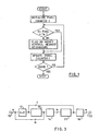
- FIG. 1 shows a flowchart of a general method for suppression of the perception of flicker in an interlaced video image.
- the flowchart describes the method for each line in a video image.
- a pixel counter I is initialized to the first pixel position in the line. Pixel i is tested against a first threshold. If the intensity value of pixel i is less than the first threshold then the pixel is considered to be black or near-black and one or more flag bits are set in the intensity value representations of the vertical nearest neighbor pixels. Alternatively, if the vertical nearest neighbor pixels have intensity values greater than AO, indicating white or near-white pixels, the intensity values may be immediately modified to hexadecimal values AO.
- the pixel counter I is then updated and a next pixel is tested until the end of line is reached at which time a next line may be modified until the image has been completely flicker suppressed.
- FIG. 2 a second embodiment of the flicker suppression method according to the present invention will be described.
- Three lines of the image are stored in line buffers with buffer A storing the previous line, buffer B storing the current line and buffer C storing the next line.
- the next line buffer C is tested to determine if the contents represent all white pixels. If not, then buffer C is set to values representing all white pixels.
- the least significant bit in the buffer at the corresponding position in buffer C is set to flag a black in the line above and the next least significant bit for the current pixel position in the line is set in the preceding line buffer A to flag a black pixel in the line below.
- the decoded data representing the black or near-black pixel at the current pixel position in the line is entered in current line buffer B. These steps are shown in FIG. 2 by the blocks labeled decode b where b is the ith pixel in buffer B and testing for b not in the white state. If the intensity value of pixel b is not white, then the intensity value of pixel b is stored and tested against a threshold representing a black level.
- pixel a which is the ith pixel in the buffer A has a flag bit set in the least significant position
- pixel c which is the ith pixel in next line buffer C has a flag bit set in the next to least significant bit position as described above.
- the preceding line stored in buffer A is transferred to a video buffer through a look-up table having a transfer function such as shown in TABLE II below which modifies white or near-white pixel intensity values to a-predetermined flicker suppression level such as hexadecimal A0 (identified in TABLE II below as W) if either of the two least significant bits is set indicating a vertically adjacent black or near-black pixel either above or below the current pixel. If then endif Where:
- FIG. 3 an apparatus embodiment of the present invention will be described.
- a digital video input appears at line 10 as an input to first threshold detector 12 and first lookup table 14.
- Detector 12 tests the intensity value of a current pixel against a first threshold representing black or near black.
- the output of detector 12 is connected to a 512x1 line buffer shift register 16 and to second lookup table 18.
- the output of line buffer 16 is connected to an input of first lookup table 14.
- Lookup tables 14 and 18 (which may be identical) provides an output intensity value for a current pixel which may be modified if a black or near black pixel was present at the same pixel position on the previous line as indicated by the output of line buffer 16 and the current pixel value is white or near white.
- the transfer function of lookup tables 14 and 18 is shown in Table III below.
- lookup table 14 is passed through a 512xN line buffer shift register 20 and presented to lookup table 18 at the same time as an output of detector 12 which indicates whether the current pixel position on the next line is black or near black.
- Lookup table 18 then operates in the same manner as lookup table 14 but with respect to a black or near black pixel on the next line in which case the intensity value of the current pixel may be modified if above a suppression value such as A0.
- lookup table 18 may be structured to produce a second suppression value of lower intensity value than the AO suppression value to provide greater suppression of flicker when a white pixel is sandwiched between two black pixels.
- the second suppression value may be set to 90 or 80.
Landscapes
- Engineering & Computer Science (AREA)
- Multimedia (AREA)
- Signal Processing (AREA)
- Picture Signal Circuits (AREA)
- Controls And Circuits For Display Device (AREA)
- Television Systems (AREA)
- Transforming Electric Information Into Light Information (AREA)
- Testing, Inspecting, Measuring Of Stereoscopic Televisions And Televisions (AREA)
Applications Claiming Priority (2)
| Application Number | Priority Date | Filing Date | Title |
|---|---|---|---|
| US58960384A | 1984-03-14 | 1984-03-14 | |
| US589603 | 1984-03-14 |
Publications (2)
| Publication Number | Publication Date |
|---|---|
| EP0156134A2 true EP0156134A2 (de) | 1985-10-02 |
| EP0156134A3 EP0156134A3 (de) | 1988-08-31 |
Family
ID=24358699
Family Applications (1)
| Application Number | Title | Priority Date | Filing Date |
|---|---|---|---|
| EP85101322A Withdrawn EP0156134A3 (de) | 1984-03-14 | 1985-02-08 | Flimmerunterdrückung in Video-Bildern nach dem Zeilensprungverfahren |
Country Status (3)
| Country | Link |
|---|---|
| EP (1) | EP0156134A3 (de) |
| JP (1) | JPS60201391A (de) |
| CA (1) | CA1236563A (de) |
Families Citing this family (1)
| Publication number | Priority date | Publication date | Assignee | Title |
|---|---|---|---|---|
| JP2589953B2 (ja) * | 1993-03-30 | 1997-03-12 | 松下電器産業株式会社 | 文字・画像データ生成装置及び方法 |
Family Cites Families (2)
| Publication number | Priority date | Publication date | Assignee | Title |
|---|---|---|---|---|
| FR2406359A1 (fr) * | 1977-10-11 | 1979-05-11 | Thomson Csf | Procede et dispositif de traitement d'image pour systeme de visualisation et systeme de visualisation comprenant un tel dispositif |
| NL7901119A (nl) * | 1979-02-13 | 1980-08-15 | Philips Nv | Beeldweergeefinrichting voor het als een tweevoudig geinterlinieerd televisiebeeld weergeven van een door een beeldsignaalgenerator opgewekt tweewaardig signaal. |
-
1984
- 1984-12-28 JP JP59275067A patent/JPS60201391A/ja active Granted
-
1985
- 1985-01-25 CA CA000472899A patent/CA1236563A/en not_active Expired
- 1985-02-08 EP EP85101322A patent/EP0156134A3/de not_active Withdrawn
Also Published As
| Publication number | Publication date |
|---|---|
| EP0156134A3 (de) | 1988-08-31 |
| CA1236563A (en) | 1988-05-10 |
| JPH0256677B2 (de) | 1990-11-30 |
| JPS60201391A (ja) | 1985-10-11 |
Similar Documents
| Publication | Publication Date | Title |
|---|---|---|
| US4799105A (en) | Modified technique for suppression of flicker in interlaced video images | |
| US5418574A (en) | Video signal correction apparatus which detects leading and trailing edges to define boundaries between colors and corrects for bleeding | |
| US5034990A (en) | Edge enhancement error diffusion thresholding for document images | |
| US4695884A (en) | Correction of shading effects in video images | |
| US5097327A (en) | Apparatus for detecting a moving object in a motion picture sequence | |
| JPH0865510A (ja) | 誤差拡散方法、誤差拡散システム及び誤差生成方法 | |
| US6175659B1 (en) | Method and apparatus for image scaling using adaptive edge enhancement | |
| JPH0865508A (ja) | 誤差拡散方法、誤差拡散システム及び誤差生成方法 | |
| JPH02253765A (ja) | 画像処理装置 | |
| JPH01113789A (ja) | 中間調表示装置 | |
| US5570461A (en) | Image processing using information of one frame in binarizing a succeeding frame | |
| US6587117B1 (en) | Apparatus and method for adaptive transformation of fractional pixel coordinates for calculating color values | |
| EP0300502A2 (de) | Steuersystem zum Umdrehen von Seiten mit grosser Geschwindigkeit | |
| CA1306540C (en) | Image-processing apparatus | |
| EP0156134A2 (de) | Flimmerunterdrückung in Video-Bildern nach dem Zeilensprungverfahren | |
| US5719793A (en) | Recursive noise reduction device having improved adaptability with respect to input image data | |
| EP0528366B1 (de) | Verfahren und Schaltungsanordnung zur Bewegungsdetektion in einem Fernsehbild | |
| KR100255687B1 (ko) | 영상처리방법 및 장치 | |
| JPH0364166A (ja) | 画像処理装置 | |
| KR100245820B1 (ko) | Z버퍼링을 지원하는 부동소수점 비교회로 | |
| JP2857906B2 (ja) | 中間調の2値化処理装置 | |
| JPH06233136A (ja) | 画像処理方法 | |
| JPH0865583A (ja) | ディスプレイ装置 | |
| KR960007917B1 (ko) | 팩시밀리의 화상에지 강조장치 및 방법 | |
| JP3077414B2 (ja) | 画像処理方法 |
Legal Events
| Date | Code | Title | Description |
|---|---|---|---|
| PUAI | Public reference made under article 153(3) epc to a published international application that has entered the european phase |
Free format text: ORIGINAL CODE: 0009012 |
|
| AK | Designated contracting states |
Designated state(s): DE FR GB IT |
|
| 17P | Request for examination filed |
Effective date: 19860124 |
|
| PUAL | Search report despatched |
Free format text: ORIGINAL CODE: 0009013 |
|
| AK | Designated contracting states |
Kind code of ref document: A3 Designated state(s): DE FR GB IT |
|
| 17Q | First examination report despatched |
Effective date: 19900531 |
|
| STAA | Information on the status of an ep patent application or granted ep patent |
Free format text: STATUS: THE APPLICATION HAS BEEN WITHDRAWN |
|
| 18W | Application withdrawn |
Withdrawal date: 19911206 |
|
| R18W | Application withdrawn (corrected) |
Effective date: 19911206 |
|
| RIN1 | Information on inventor provided before grant (corrected) |
Inventor name: MITCHELL, JOAN LAVERNE Inventor name: PENNEBAKEN, WILLLIAM BOONE |