EP0156283A1 - Verfahren und Gerät zur Regelung eines bürstenlosen Wechselstrommotors - Google Patents
Verfahren und Gerät zur Regelung eines bürstenlosen Wechselstrommotors Download PDFInfo
- Publication number
- EP0156283A1 EP0156283A1 EP85103123A EP85103123A EP0156283A1 EP 0156283 A1 EP0156283 A1 EP 0156283A1 EP 85103123 A EP85103123 A EP 85103123A EP 85103123 A EP85103123 A EP 85103123A EP 0156283 A1 EP0156283 A1 EP 0156283A1
- Authority
- EP
- European Patent Office
- Prior art keywords
- motor
- signal
- inverter
- direct current
- controlling
- Prior art date
- Legal status (The legal status is an assumption and is not a legal conclusion. Google has not performed a legal analysis and makes no representation as to the accuracy of the status listed.)
- Withdrawn
Links
Images


Classifications
-
- D—TEXTILES; PAPER
- D06—TREATMENT OF TEXTILES OR THE LIKE; LAUNDERING; FLEXIBLE MATERIALS NOT OTHERWISE PROVIDED FOR
- D06F—LAUNDERING, DRYING, IRONING, PRESSING OR FOLDING TEXTILE ARTICLES
- D06F37/00—Details specific to washing machines covered by groups D06F21/00 - D06F25/00
- D06F37/30—Driving arrangements
- D06F37/304—Arrangements or adaptations of electric motors
-
- H—ELECTRICITY
- H02—GENERATION; CONVERSION OR DISTRIBUTION OF ELECTRIC POWER
- H02M—APPARATUS FOR CONVERSION BETWEEN AC AND AC, BETWEEN AC AND DC, OR BETWEEN DC AND DC, AND FOR USE WITH MAINS OR SIMILAR POWER SUPPLY SYSTEMS; CONVERSION OF DC OR AC INPUT POWER INTO SURGE OUTPUT POWER; CONTROL OR REGULATION THEREOF
- H02M7/00—Conversion of AC power input into DC power output; Conversion of DC power input into AC power output
- H02M7/42—Conversion of DC power input into AC power output without possibility of reversal
- H02M7/44—Conversion of DC power input into AC power output without possibility of reversal by static converters
- H02M7/48—Conversion of DC power input into AC power output without possibility of reversal by static converters using discharge tubes with control electrode or semiconductor devices with control electrode
- H02M7/53—Conversion of DC power input into AC power output without possibility of reversal by static converters using discharge tubes with control electrode or semiconductor devices with control electrode using devices of a triode or transistor type requiring continuous application of a control signal
- H02M7/537—Conversion of DC power input into AC power output without possibility of reversal by static converters using discharge tubes with control electrode or semiconductor devices with control electrode using devices of a triode or transistor type requiring continuous application of a control signal using semiconductor devices only, e.g. single switched pulse inverters
- H02M7/5387—Conversion of DC power input into AC power output without possibility of reversal by static converters using discharge tubes with control electrode or semiconductor devices with control electrode using devices of a triode or transistor type requiring continuous application of a control signal using semiconductor devices only, e.g. single switched pulse inverters in a bridge configuration
- H02M7/53871—Conversion of DC power input into AC power output without possibility of reversal by static converters using discharge tubes with control electrode or semiconductor devices with control electrode using devices of a triode or transistor type requiring continuous application of a control signal using semiconductor devices only, e.g. single switched pulse inverters in a bridge configuration with automatic control of output voltage or current
- H02M7/53875—Conversion of DC power input into AC power output without possibility of reversal by static converters using discharge tubes with control electrode or semiconductor devices with control electrode using devices of a triode or transistor type requiring continuous application of a control signal using semiconductor devices only, e.g. single switched pulse inverters in a bridge configuration with automatic control of output voltage or current with analogue control of three-phase output
-
- H—ELECTRICITY
- H02—GENERATION; CONVERSION OR DISTRIBUTION OF ELECTRIC POWER
- H02P—CONTROL OR REGULATION OF ELECTRIC MOTORS, ELECTRIC GENERATORS OR DYNAMO-ELECTRIC CONVERTERS; CONTROLLING TRANSFORMERS, REACTORS OR CHOKE COILS
- H02P27/00—Arrangements or methods for the control of AC motors characterised by the kind of supply voltage
- H02P27/04—Arrangements or methods for the control of AC motors characterised by the kind of supply voltage using variable-frequency supply voltage, e.g. inverter or converter supply voltage
- H02P27/06—Arrangements or methods for the control of AC motors characterised by the kind of supply voltage using variable-frequency supply voltage, e.g. inverter or converter supply voltage using DC to AC converters or inverters
- H02P27/08—Arrangements or methods for the control of AC motors characterised by the kind of supply voltage using variable-frequency supply voltage, e.g. inverter or converter supply voltage using DC to AC converters or inverters with pulse width modulation
-
- Y—GENERAL TAGGING OF NEW TECHNOLOGICAL DEVELOPMENTS; GENERAL TAGGING OF CROSS-SECTIONAL TECHNOLOGIES SPANNING OVER SEVERAL SECTIONS OF THE IPC; TECHNICAL SUBJECTS COVERED BY FORMER USPC CROSS-REFERENCE ART COLLECTIONS [XRACs] AND DIGESTS
- Y02—TECHNOLOGIES OR APPLICATIONS FOR MITIGATION OR ADAPTATION AGAINST CLIMATE CHANGE
- Y02B—CLIMATE CHANGE MITIGATION TECHNOLOGIES RELATED TO BUILDINGS, e.g. HOUSING, HOUSE APPLIANCES OR RELATED END-USER APPLICATIONS
- Y02B40/00—Technologies aiming at improving the efficiency of home appliances, e.g. induction cooking or efficient technologies for refrigerators, freezers or dish washers
Definitions
- the present invention relates to a method and a device for controlling a brushless alternating current motor driven by an inverter connected to a constant voltage direct current supply.
- GB-A-1 020 214 the direct current- supplied to the inverter is sensed. This control signal is then used to control the inverter such that the motor speed is held substantially constant.
- the present invention uses a different approach in that all information needed is taken out by means of sensing the direct current fed to the inverter and passing negative pulses in the sensed signal through a peak detector and a regulator, as defined in the appended claims, to obtain a control signal for controlling the operation of the inverter. Since the voltage and frequency supplied to the motor terminals are entirely controlled by controlling the operation of the inverter, the voltage of the direct current source will be substantially constant. This means that all variations in the operational state of the motor are reflected in variations in the direct current supplied to the inverter.
- negative pulses obtained when the switching elements of the inverter are switched off are sensed.
- the sensed signal is then used to control the voltage supplied to the motor terminals such that these pulses obtain a predetermined level.
- the magnitude of these negative pulses reflect the magnetic state of the motor.
- fig 1 shows a washing machine with part of the control system.
- Fig 2 shows the motor drive system.
- Fig 3 shows the controller of fig 2.
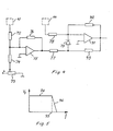
- Fig 4 shows a regulator of fig 3.
- Fig 5 shows a transfer function for the regulator according to fig. 4.
- the embodiment of the invention shown in fig 1 comprises a washing machine 201.
- the washing machine of Fig 1 includes the motor, the inverter and other power circuits feeding the motor and the major part of the control system. These parts are described more in detail in connection with figs 2-5.
- Washing machine 201 is provided with an input 19 for the supply of a frequency demand signal. This signal is delivered by a timer 202 in which the washing program is stored. The frequency demand signal is the basic demand for rotational speed. Timer 202 also delivers start signals to input 20.
- Washing machine 201 is further provided with an input 21 for the selection of rotational direction and an output 39 which delivers a signal corresponding to the rotational speed of the motor.
- output 39 becomes logical zero. Only then is the signal fed to input 21 allowed to change its logical state so that a start signal from timer 202 will cause rotation in the opposite direction.
- the drive system shown in fig.2 comprises a threephase rectifier 22 which is connected to a standard fixed frequency mains supply.
- the rectifier delivers direct current of substantially constant voltage to conduits 24, 25 , which constitute a positive 24 and a negative 25 terminal of a direct current supply for an inverter.
- the inverter comprises six switching elements 31-36 for successively connecting motor terminals 28, 29, 30 on a brushless alternating current motor 23 to the positive terminal 24 and the negative terminal 25 of the direct current supply.
- the switching elements are in the drawing shown as transistors but could, of course, be combinations of thyristors or other elements.
- a diode 27 is placed in anti-parallel over each transistor to take care of reactive currents at the switching off of the transistor.
- control signals are supplied from outputs 11-16 on a controller 10 as shown in fig. 3. These control signals are supplied via amplifiers 26 to the base of respective transistor. Controller 10 is provided with inputs 17, 18 through which the direct current in conduit 24 is sensed. Controller 10 is further provided with an output 39 and inputs 19, 20, 21. Output 39 is only used if it during operation is desired to change the direction of rotation of the motor. The direction of rotation is selected by applying a logical signal to input 21. If rotation in only one direction is desired input 21 is connected either to a positive voltage or common. The speed of motor 23 may be changed by variation of a voltage applied to input 19. If, as for instance in a grinding machine, it is desired to drive the motor at a certain speed, input 19 is connected to a suitable voltage corresponding to the desired speed. Input 20 is intended for receiving a start/stop signal by which rotation or no rotation is chosen.
- Controller 10 which is shown more in detail in fig. 3, comprises a sensing means 40 for sensing the direct current in conduit 24. This current is presented as a voltage between inputs 17 and 18.
- the output signal of sensing means 40 is applied to a first peak detector 41, a low-pass filter 42, a second peak detector 43 and a comparator 49.
- Peak detectors 41 and 43 comprise diodes to react on positive and negative signals respectively.
- the peak detectors also comprise low-pass filters.
- First peak detector 41 preferably has a time constant of about 4/f where f is the maximum fundamental frequency of the current supplied to motor 23.
- the cut-off frequency, -3dB, of peak detector 41 is preferably about 0.1 f.
- Lowpass filter 42 preferably has about the same cut-off frequency.
- Second peak detector 43 preferably has a time constant of about 1/f and a cut-off frequency of about 0.5 f.
- the peak value signal from peak detector 41 is supplied to a first regulator 45, which is shown more in detail in fig. 4.
- Input signals from inputs 19 and 20 are supplied to a means 44 in form of a ramp generator.
- Ramp generator 44 comprises one or two operational amplifiers connected as integrators to supply regulator 45 with an increasing ramp voltage at motor start acceleration and a decreasing ramp voltage at motor stop deceleration. In this way it is possible to avoid that the normal speed maximum load current is exceeded when the motor is started or stopped.
- a change in the speed demand signal at input 19 is also integrated by ramp generator 44. Thus it takes some time before the output of ramp generator 44 becomes fully adapted to the input signals.
- the peak value signal from first peak-detector 41 is applied to one of the inputs of operational amplifier 75 via resistor 72. This signal is compared with a reference signal preset on variable resistor 73 and fed to the amplifier via resistor 74.
- the amplifier is provided with a feed-back resistor 76.
- the output signal of amplifier 75 is via a resistor 77 applied to diode 79.
- the output signal from ramp generator 44 is via resistor 78 supplied to one of the inputs of operational amplifier 91.
- Amplifier 91 is provided with a first feed-back resistor 92 and a second feed-back resistor 93 in series with diode 79. Resistor 93 has a much lower resistance than resistor 92. Preferably the ratio is about 1/20.
- the frequency controlling signal from the output of amplifier 91 is delivered to a voltage-controlled oscillator 47, output 39 and an analog divider 46, e.g. Analog Devices AD 534.
- the voltage-controlled oscillator produces an output signal whose frequency is proportional to the input voltage.
- the rectified mean value signal obtained from low-pass filter 42 corresponds to the power supplied to motor 23 because the voltage of the direct current supply 24, 25 is substantially constant.
- This signal is supplied to divider 46 where it is divided with the frequency controlling signal, which is the demand signal for rotational speed of motor 23.
- the output signal of divider 46 will thus correspond to the torque demand from motor 23.
- This output signal, first voltage controlling signal is supplied to a second regulator 48.
- the negative peak value signal, second voltage controlling signal, obtained from second peak detector 43 is also supplied to regulator 48 so that the output signal of regulator 48 becomes proportional to the difference between the first and the second voltage controlling signals.
- the negative peak value signal from peak detector 43 corresponds to the degree of magnetization of motor 23.
- This signal is obtained from negative pulses which are fed back to the direct current source when the transistors 31-36 are switched off.
- By controlling the level of these negative pulses it is possible to obtain a predetermined level of magnetization of the motor allowing both a high power to weight ratio and the avoiding of oversaturation, which would give unacceptable losses.
- the output signal from voltage-controlled oscillator 47 is supplied to a timer 51, preferably an industrial timer of standard type 555, and to a divider 50.
- Divider 50 is preferably a programmable counter which delivers a pulse train having a frequency which is equal to the frequency of the input signal divided by a chosen constant.
- Timer 51 delivers a pulse train whose frequency is equal to the frequency of the output signal from voltage-controlled oscillator 47.
- the pulse width is controlled by the output signal from second regulator 48.
- This pulse train is supplied to AND gates 81, 83 and 85.
- the pulse train from divider 50 is supplied as clock signal to ring counter 52. In the ring counter a 1 and five 0's are stored.
- the 1 is shifted around by the pulse train from output 53 through 58 and back to 53. This makes one period of the fundamental frequency of the current supplied to motor 23.
- Outputs 53-58 of ring counter 52 are decoded by OR gates 59, 60 and 61. The output of each of these gates is high half the time and low half the time.
- a logic signal inverter 62 and NAND gates 63-68 are provided for selecting direction of rotation of motor 23.
- the output signals of gates 59, 60 and 61 are supplied to AND gates 81-86 for controlling the actuation of switching transistors 31-36 in the inverter.
- the inputs of gates 82, 84 and 86 are provided with logic signal inverters 71, 70 and 69 respectively.
- the mean value over half a period of the fundamental frequency of the voltage applied to any of the motor terminals will change simultaneously with the frequency as required by basic electromagnetic laws. Additional control of the mean value voltage is obtained by variation of the pulse width, which is controlled by regulator 48.
Landscapes
- Engineering & Computer Science (AREA)
- Power Engineering (AREA)
- Textile Engineering (AREA)
- Control Of Motors That Do Not Use Commutators (AREA)
- Control Of Ac Motors In General (AREA)
Applications Claiming Priority (2)
| Application Number | Priority Date | Filing Date | Title |
|---|---|---|---|
| CH8097/81 | 1981-12-18 | ||
| CH8097/81A CH664654A5 (fr) | 1981-12-18 | 1981-12-18 | Procede et dispositif pour la commande d'un moteur a courant alternatif sans balai. |
Related Parent Applications (1)
| Application Number | Title | Priority Date | Filing Date |
|---|---|---|---|
| EP82850249.2 Division | 1982-12-02 |
Publications (1)
| Publication Number | Publication Date |
|---|---|
| EP0156283A1 true EP0156283A1 (de) | 1985-10-02 |
Family
ID=4335110
Family Applications (3)
| Application Number | Title | Priority Date | Filing Date |
|---|---|---|---|
| EP85103122A Expired EP0156282B1 (de) | 1981-12-18 | 1982-12-02 | Verfahren und Gerät zur Regelung eines bürstenlosen Wechselstrommotors |
| EP82850249A Expired EP0083326B1 (de) | 1981-12-18 | 1982-12-02 | Verfahren und Gerät zur Regelung eines bürstenlosen Wechselstrommotors |
| EP85103123A Withdrawn EP0156283A1 (de) | 1981-12-18 | 1982-12-02 | Verfahren und Gerät zur Regelung eines bürstenlosen Wechselstrommotors |
Family Applications Before (2)
| Application Number | Title | Priority Date | Filing Date |
|---|---|---|---|
| EP85103122A Expired EP0156282B1 (de) | 1981-12-18 | 1982-12-02 | Verfahren und Gerät zur Regelung eines bürstenlosen Wechselstrommotors |
| EP82850249A Expired EP0083326B1 (de) | 1981-12-18 | 1982-12-02 | Verfahren und Gerät zur Regelung eines bürstenlosen Wechselstrommotors |
Country Status (9)
| Country | Link |
|---|---|
| EP (3) | EP0156282B1 (de) |
| JP (2) | JPS58108984A (de) |
| AT (1) | ATE41574T1 (de) |
| AU (1) | AU559829B2 (de) |
| BR (1) | BR8207209A (de) |
| CH (1) | CH664654A5 (de) |
| DE (1) | DE3272772D1 (de) |
| SE (1) | SE8204003L (de) |
| ZA (1) | ZA828861B (de) |
Cited By (2)
| Publication number | Priority date | Publication date | Assignee | Title |
|---|---|---|---|---|
| EP0394178A3 (de) * | 1989-04-17 | 1992-01-15 | Emerson Electric Co. | Antriebssystem für Haushaltsgeräte |
| EP0392962A3 (de) * | 1989-04-12 | 1992-01-15 | Emerson Electric Co. | Geschwindigkeitsregler für eine durch einen Wechselrichter angetriebene Waschmaschine |
Families Citing this family (21)
| Publication number | Priority date | Publication date | Assignee | Title |
|---|---|---|---|---|
| JPS60193880U (ja) * | 1984-06-04 | 1985-12-24 | 本田技研工業株式会社 | 車両のキヤリア装置 |
| GB2167251B (en) * | 1984-11-21 | 1988-10-05 | Barry Wayne Williams | Induction motor drive circuits |
| JPS61280885A (ja) * | 1985-05-13 | 1986-12-11 | 三洋電機株式会社 | 脱水機 |
| NL8501987A (nl) * | 1985-07-11 | 1987-02-02 | Cornelius Johannus Petrus Cox | Frequentie- en/of spanningsregelinrichting voor ten minste gedeeltelijk inductieve belastingen, in het bijzonder draaistroommotoren. |
| FI85062C (fi) * | 1988-11-14 | 1992-02-25 | Kone Oy | Foerfarande och anordning foer maetning av stroemmar vid en frekvensomformare. |
| JPH03222991A (ja) * | 1990-01-29 | 1991-10-01 | Nippon Kentetsu Co Ltd | 洗濯機の運転制御装置 |
| JPH03222993A (ja) * | 1990-01-29 | 1991-10-01 | Nippon Kentetsu Co Ltd | 洗濯機の運転制御方法 |
| JP2544000B2 (ja) * | 1990-03-30 | 1996-10-16 | 株式会社東芝 | 洗濯機 |
| TR26731A (tr) * | 1990-10-10 | 1995-05-15 | Icotron Sa | BIR FREKANS DüZENLEYICIYLE BESLENEN ES ZAMANLI OLMAYAN BIR MOTORUN YüK DURUMUNUN BELIRLENMESI üZERINE BIR YÖNTEM VE YÖNTEMIN UYGULANMASI ICIN TERTIBAT. |
| JP2644386B2 (ja) * | 1991-04-20 | 1997-08-25 | シャープ株式会社 | 洗濯機 |
| US5409688A (en) | 1991-09-17 | 1995-04-25 | Sonus Pharmaceuticals, Inc. | Gaseous ultrasound contrast media |
| MX9205298A (es) | 1991-09-17 | 1993-05-01 | Steven Carl Quay | Medios gaseosos de contraste de ultrasonido y metodo para seleccionar gases para usarse como medios de contraste de ultrasonido |
| US6723303B1 (en) | 1991-09-17 | 2004-04-20 | Amersham Health, As | Ultrasound contrast agents including protein stabilized microspheres of perfluoropropane, perfluorobutane or perfluoropentane |
| HUT72323A (en) * | 1993-01-25 | 1996-04-29 | Sonus Pharma Inc | Phase shift colloids as ultrasound contrast agents |
| US5558855A (en) * | 1993-01-25 | 1996-09-24 | Sonus Pharmaceuticals | Phase shift colloids as ultrasound contrast agents |
| IL108416A (en) | 1993-01-25 | 1998-10-30 | Sonus Pharma Inc | Phase shift colloids as ultrasound contrast agents |
| ATE217655T1 (de) * | 1997-02-17 | 2002-06-15 | Miele & Cie | Wäschebehandlungsgerät mit einem auf der trommelwelle angeordneten antriebsmotor |
| JP3524376B2 (ja) * | 1998-03-31 | 2004-05-10 | 株式会社東芝 | 脱水兼用洗濯機 |
| DE19825722A1 (de) * | 1998-06-09 | 1999-12-16 | Philips Patentverwaltung | Schaltungsanordnung zum Speisen eines Elektromotors |
| DE10137159A1 (de) | 2001-07-30 | 2003-02-20 | Hilti Ag | Schlagendes Elektrohandwerkzeuggerät |
| JP4467874B2 (ja) * | 2002-09-30 | 2010-05-26 | キヤノン株式会社 | 画像形成装置 |
Citations (4)
| Publication number | Priority date | Publication date | Assignee | Title |
|---|---|---|---|---|
| GB1020214A (en) * | 1962-05-29 | 1966-02-16 | Westinghouse Brake & Signal | Improvements relating to control systems for electric motors |
| US3402336A (en) * | 1965-10-13 | 1968-09-17 | Cutler Hammer Inc | Adjustable frequency a.c. motor control system with low speed compensation |
| US4051418A (en) * | 1975-11-03 | 1977-09-27 | Berto Gerald N O | Three phase a.c. motor drive system |
| FR2439503A1 (fr) * | 1978-10-18 | 1980-05-16 | Westinghouse Electric Corp | Systeme d'entrainement peu onereux a moteur a induction a couple constant et a vitesse variable |
Family Cites Families (3)
| Publication number | Priority date | Publication date | Assignee | Title |
|---|---|---|---|---|
| FR1494065A (fr) * | 1965-05-10 | 1967-09-08 | Const De Vaux Andigny Atel | Détecteur-amplificateur pour signaux de faible niveau et dispositifs en comportant application |
| JPS5130908A (en) * | 1974-09-10 | 1976-03-16 | Hitachi Ltd | Sairisutamoota nochokuryukiburashikansotodenatsukenshutsuhoshiki |
| JPS5250519A (en) * | 1975-10-21 | 1977-04-22 | Toshiba Corp | Frequency convertor |
-
1981
- 1981-12-18 CH CH8097/81A patent/CH664654A5/fr not_active IP Right Cessation
-
1982
- 1982-06-29 SE SE8204003A patent/SE8204003L/xx not_active Application Discontinuation
- 1982-12-02 EP EP85103122A patent/EP0156282B1/de not_active Expired
- 1982-12-02 ZA ZA828861A patent/ZA828861B/xx unknown
- 1982-12-02 DE DE8282850249T patent/DE3272772D1/de not_active Expired
- 1982-12-02 EP EP82850249A patent/EP0083326B1/de not_active Expired
- 1982-12-02 AT AT85103122T patent/ATE41574T1/de active
- 1982-12-02 EP EP85103123A patent/EP0156283A1/de not_active Withdrawn
- 1982-12-12 AU AU91709/82A patent/AU559829B2/en not_active Ceased
- 1982-12-13 BR BR8207209A patent/BR8207209A/pt not_active IP Right Cessation
- 1982-12-17 JP JP57220380A patent/JPS58108984A/ja active Pending
- 1982-12-18 JP JP57221126A patent/JPS58155894A/ja active Granted
Patent Citations (4)
| Publication number | Priority date | Publication date | Assignee | Title |
|---|---|---|---|---|
| GB1020214A (en) * | 1962-05-29 | 1966-02-16 | Westinghouse Brake & Signal | Improvements relating to control systems for electric motors |
| US3402336A (en) * | 1965-10-13 | 1968-09-17 | Cutler Hammer Inc | Adjustable frequency a.c. motor control system with low speed compensation |
| US4051418A (en) * | 1975-11-03 | 1977-09-27 | Berto Gerald N O | Three phase a.c. motor drive system |
| FR2439503A1 (fr) * | 1978-10-18 | 1980-05-16 | Westinghouse Electric Corp | Systeme d'entrainement peu onereux a moteur a induction a couple constant et a vitesse variable |
Cited By (2)
| Publication number | Priority date | Publication date | Assignee | Title |
|---|---|---|---|---|
| EP0392962A3 (de) * | 1989-04-12 | 1992-01-15 | Emerson Electric Co. | Geschwindigkeitsregler für eine durch einen Wechselrichter angetriebene Waschmaschine |
| EP0394178A3 (de) * | 1989-04-17 | 1992-01-15 | Emerson Electric Co. | Antriebssystem für Haushaltsgeräte |
Also Published As
| Publication number | Publication date |
|---|---|
| ZA828861B (en) | 1983-09-28 |
| DE3272772D1 (en) | 1986-09-25 |
| ATE41574T1 (de) | 1989-04-15 |
| CH664654A5 (fr) | 1988-03-15 |
| JPS58108984A (ja) | 1983-06-29 |
| SE8204003L (sv) | 1983-06-19 |
| EP0156282A1 (de) | 1985-10-02 |
| JPH0255079B2 (de) | 1990-11-26 |
| EP0083326B1 (de) | 1986-08-20 |
| EP0156282B1 (de) | 1989-03-15 |
| AU9170982A (en) | 1983-06-23 |
| AU559829B2 (en) | 1987-03-19 |
| EP0083326A1 (de) | 1983-07-06 |
| JPS58155894A (ja) | 1983-09-16 |
| SE8204003D0 (sv) | 1982-06-29 |
| BR8207209A (pt) | 1983-10-11 |
Similar Documents
| Publication | Publication Date | Title |
|---|---|---|
| EP0156282B1 (de) | Verfahren und Gerät zur Regelung eines bürstenlosen Wechselstrommotors | |
| US4489261A (en) | Method and means for feeding electric energy to a portable power tool | |
| EP0085285B1 (de) | Kompressor-Antriebssystem | |
| US4601351A (en) | Electrically driven hammer machine | |
| CA2027001C (en) | Dc braking of inverter-driven ac motors | |
| US4538100A (en) | DC to AC inverter and motor control system | |
| EP0013171A1 (de) | Regelgerät für einen Induktionsmotor | |
| US4843297A (en) | Microprocessor speed controller | |
| JPS6249838B2 (de) | ||
| EP0010979A1 (de) | Antriebsschaltung eines Wechselstrom-Motors mit Überlastschutz | |
| EP0078117B1 (de) | Wechselrichterschaltung | |
| US4550282A (en) | Method and device for controlling a brushless alternating current motor | |
| US3670224A (en) | Speed and voltage control means for an alternating-current motor, particularly a polyphase induction motor | |
| US6008602A (en) | Arrangement with an electronically commutated motor | |
| KR100289710B1 (ko) | 펄스 폭 변조 인버터의 전동기 직류 제동장치 | |
| EP0194400B1 (de) | Verfahren zum Anlassen eines Asynchronmotors und Gerät zur Durchführung dieses Verfahrens | |
| JPS598155B2 (ja) | インバ−タ装置の制御回路 | |
| KR950002039B1 (ko) | 인버터 구동회로의 자기 진단방법 | |
| EP0203145A1 (de) | Mikroprozessor-geschwindigkeitsregler | |
| EP0178629B1 (de) | Steuereinrichtung mit Indexeinstellung für Wechselrichtergeräte | |
| KR100290480B1 (ko) | 펄스 폭 변환 회로 | |
| JPS6315697A (ja) | 交流スピンドルモ−タ制御方法 | |
| KR930007593B1 (ko) | Ac 3상 범용 모터 제어용 서보 콘트롤 시스템 | |
| JPS611289A (ja) | モ−タ制御装置 | |
| JPS59144394A (ja) | 誘導電動機制御装置 |
Legal Events
| Date | Code | Title | Description |
|---|---|---|---|
| PUAI | Public reference made under article 153(3) epc to a published international application that has entered the european phase |
Free format text: ORIGINAL CODE: 0009012 |
|
| AC | Divisional application: reference to earlier application |
Ref document number: 83326 Country of ref document: EP |
|
| AK | Designated contracting states |
Designated state(s): AT BE CH DE FR GB IT LI LU NL |
|
| 17P | Request for examination filed |
Effective date: 19860312 |
|
| 17Q | First examination report despatched |
Effective date: 19870227 |
|
| STAA | Information on the status of an ep patent application or granted ep patent |
Free format text: STATUS: THE APPLICATION IS DEEMED TO BE WITHDRAWN |
|
| 18D | Application deemed to be withdrawn |
Effective date: 19870910 |
|
| RIN1 | Information on inventor provided before grant (corrected) |
Inventor name: OBEL, ERIK MARTIN Inventor name: LJUNG, ERIK ANDERS Inventor name: HARTWIG, CARL SVERKER MAGNUSSON |