EP0157328A2 - Abgassensor und Verfahren zu dessen Herstellung - Google Patents
Abgassensor und Verfahren zu dessen Herstellung Download PDFInfo
- Publication number
- EP0157328A2 EP0157328A2 EP85103512A EP85103512A EP0157328A2 EP 0157328 A2 EP0157328 A2 EP 0157328A2 EP 85103512 A EP85103512 A EP 85103512A EP 85103512 A EP85103512 A EP 85103512A EP 0157328 A2 EP0157328 A2 EP 0157328A2
- Authority
- EP
- European Patent Office
- Prior art keywords
- exhaust gas
- gas sensor
- compound
- sensitive member
- basno
- Prior art date
- Legal status (The legal status is an assumption and is not a legal conclusion. Google has not performed a legal analysis and makes no representation as to the accuracy of the status listed.)
- Granted
Links
Images





Classifications
-
- G—PHYSICS
- G01—MEASURING; TESTING
- G01N—INVESTIGATING OR ANALYSING MATERIALS BY DETERMINING THEIR CHEMICAL OR PHYSICAL PROPERTIES
- G01N27/00—Investigating or analysing materials by the use of electric, electrochemical, or magnetic means
- G01N27/02—Investigating or analysing materials by the use of electric, electrochemical, or magnetic means by investigating impedance
- G01N27/04—Investigating or analysing materials by the use of electric, electrochemical, or magnetic means by investigating impedance by investigating resistance
- G01N27/12—Investigating or analysing materials by the use of electric, electrochemical, or magnetic means by investigating impedance by investigating resistance of a solid body in dependence upon absorption of a fluid; of a solid body in dependence upon reaction with a fluid, for detecting components in the fluid
-
- Y—GENERAL TAGGING OF NEW TECHNOLOGICAL DEVELOPMENTS; GENERAL TAGGING OF CROSS-SECTIONAL TECHNOLOGIES SPANNING OVER SEVERAL SECTIONS OF THE IPC; TECHNICAL SUBJECTS COVERED BY FORMER USPC CROSS-REFERENCE ART COLLECTIONS [XRACs] AND DIGESTS
- Y10—TECHNICAL SUBJECTS COVERED BY FORMER USPC
- Y10T—TECHNICAL SUBJECTS COVERED BY FORMER US CLASSIFICATION
- Y10T29/00—Metal working
- Y10T29/49—Method of mechanical manufacture
- Y10T29/49002—Electrical device making
Definitions
- the present invention relates to an exhaust gas sensor wherein use is made of the variation of resistance of a metallic oxide semiconductor and to a process for producing the same, and more particularly to improvements in exhaust sensor materials.
- Exhaust gas sensors are used for detecting the ; air/fuel ratio ⁇ of exhaust gases or O 2 , CO or like compo-, nent of exhaust gases. They are chiefly used for controlling the air/fuel ratio for motor vehicle engines, boilers, etc.. and for preventing incomplete combustion in air heaters.
- the sensor controls the air/fuel ratio x at the point of equivalence (where the air/fuel ratio ⁇ is 1.00) or in the lean burn region (in which the air/fuel ratio is not smaller than 1).
- the sensor detects the reduction of the air/fuel ratio ⁇ to below 1 and detects incomplete combustion.
- Exhaust gas sensors are known in which a gas sensitive member made of Sn0 2 is connected to at least one pair of electrodes (as disclosed, for example, in U.S. Patent No. 4,459,577,corresponding to German Patent Application No. 3,313,752). With the exhaust gas sensor of the patent, the growth of crystals of Sn0 2 is controlled to give the sensor improved durability against reducing atmospheres of high temperatures.
- An object of the present invention is to provide a novel exhaust gas sensor material having improved durability to reducing atmospheres of high temperatures and suppressed sensitivity to unburnt combustible gases to prevent the reduction in the precision of detection due to unburnt gases, the sensor material further having improved responsiveness to changes of atmosphere.
- Another object of the present invention is to provide a gas sensitive member which is prevented from decomposition due to a solid-phase reaction between the member and alumina when alumina is used as a substrate.
- Another object of the present invention is to provide a process for producing exhaust gas sensor materials having the above-mentioned properties.
- the present invention provides an exhaust gas sensor which is characterized in that at least one pair of electrodes is connected to a gas sensitive member comprising a compound ASnO 3- ⁇ wherein A is at least one member selected from the group consisting of Ba, Sr, Ca and Ra, and 6 is a non-stoichiometic parameter.
- the compounds ASnO 3- ⁇ are perovskite compounds ("National Bureau of Standards Monograph," Vol. 25, Sec. 3, p. ll, 1964).
- BaSnO 3- ⁇ and RaSnO 3- ⁇ which are perfectly n-type semiconductors, increase in resistance in response to a change from x ⁇ 1 to ⁇ > 1 and also to a further increase in ⁇ in the lean burn region.
- BaSnO 3- ⁇ and RaSnO 3- ⁇ are equivalent to each other and match in characteristics, but it is preferable to use BaSnO 3- ⁇ since RaSnO 3- ⁇ is radioactive.
- SrSnO 3- ⁇ and CaSnO 3- ⁇ are substances having both n-type properties and p-type properties, exhibit an increased resistance value in response to a change from ⁇ ⁇ 1 to ⁇ > 1 (n-type properties) and decreases in resistance when ⁇ further increases in the lean burn region (p-type properties).
- the resistance value of these compounds increases in the order of BaSnO 3- ⁇ ⁇ SrSnO 3- ⁇ ⁇ CaSnO 3- ⁇ ' and the sensitivity thereof to a change from ⁇ ⁇ 1 to > > 1 decreases in the order of BaSnO 3- ⁇ > SrSnO 3- ⁇ > CaSnO 3- ⁇ .
- the absolute value of the oxygen sensitivity increases in the order of BaSnO 3- ⁇ > CaSnO 3- ⁇ ⁇ SrSnO 3- ⁇ .
- the sensitivity of these compounds increases as the growth of crystals is promoted, such that it increases greatly when the compounds are baked at a temperature of at least 1260° C.
- the material for the gas sensitive member is obtained by baking a compound ASNO 3- ⁇ or a substance which is converted to the compound ASNO 3- ⁇ when heated, in a non-reducing atmosphere, preferably at a temperature of 1000 to 2000° C for 30 minutes to 20 hours.
- An exhaust gas sensor is prepared with use of the gas sensitive member, for example, by connecting a pair of electrodes to the gas sensitive member, causing a heat-resistant insulating substrate to support the gas sensitive member and providing a heater around the resulting assembly for heating the member at a specified temperature.
- the compound ASNO 3- ⁇ has the property of undergoing a decomposition reaction with alumina which is generally used as the material for the substrate.
- an intermediate layer of a substance which is not reactive with ASNO 3- ⁇ is interposed between the gas sensitive member and the substrate.
- preferable materials for the intermediate layer are spinel (MgA1 2 0 4 ), mullite (Al 6 si 2 O 13 ) and cordierite (Mg 2 Al 4 Si 5 O 18 ).
- the compounds ASNO 3- ⁇ will be represented without using the non-stoichiometric parameter 6.
- the value of this parameter 6, which varies with the ambient atmosphere and temperature, is usually -0.1 to 0.5.
- the term "specific surface area” as used herein and in the appended claims refers to a value measured by the B.E.T. method using N 2 as the adsorption medium.
- BaCO 3 at least 99.99% in purity and Sn0 2 at least 99.99% in purity (50 m 2 /g in specific surface area) are kneaded together in an equimolar ratio with use of water.
- BaCO 3 is used as a starting material because it contains a lesser amount of crystal water and adsorbed water, and the amount to be used can be determined with ease.
- Other Ba materials such as BaO, Ba(OH) 2 , BaCl 2 , BaSO 4 and metallic barium, are also usable although difficulty is encountered. in controlling the amount to be used.
- SnO 2 which is used similarly because it is easy to control the amount, may be replaced by SnCl 4 , SnSO 4 , Sn(OH) 4 or the like.
- the mixture is then calcined in air at 500 to 1200° C for 1 hour.
- Four different temperatures i.e. 500° C, 800° C, 1000° C and 1200° C, were used for calcination.
- the mixture is calcined at 500° C, the product is a mxiture of SnO 2 and BaCO 3 and is free from BaSnO 3 .
- the starting mixture When heated at 800° C, the starting mixture almost entirely changes to BaSnO 3 .
- the mixture is completely converted to BaSnO 3 .
- the calcining atmosphere needs only to be non-reducing. An inert atmosphere of 100% N 2 or the like, or a strongly oxidizing atmosphere of 100% 0 2 or the like may be used.
- the calcined product is pulverized wet (using water as a dispersant) in a ball mill for 30 minutes.
- the pulverized product is molded by press work into solid cylindrical pellets,3 mm in diameter and 3 mm in height, each having embedded therein a pair of Pt-Rh alloy electrodes having a diameter of 100 ⁇ .
- the pellets are baked in air to obtain gas sensitive members.
- the pellets are baked at 1000 to 2000°C for 4 hours.
- the baking temperature is at least 100° C higher than the calcining temperature.
- the baking step grows the crystals of BaSnO 3 giving the gas sensitive member durability against a high- temperature atmosphere (usually up to 950° C) during use. This step also sinters the gas sensitive member of BaSnO 3 to give enhanced mechanical strength.
- the baking atmosphere needs only to be non-reducing.
- an inert atmosphere of 100% N 2 or 100% C0 2 , or a highly oxidizing atmosphere of 100% 0 2 is usable.
- the specimen calcined at 500° C BaCO 3 reacts with Sno 2 during the baking step to produce BaSnO 3 .
- the baking step promotes the growth of crystals of BaSn0 3 , affording resistance to heat during use, especially to reducing atmospheres of high temperatures.
- the temperature at which BaSnO 3 is formed is about 800° C, while the baking temperature is much higher than this temperature. Accordingly the effect of baking is not influenced by the starting materials but is dependent on the baking temperature and time.
- the baking temperature should be at least 1000° C and not higher than 2000° C and is preferably between 1200°C andl800 C, more preferably 1260°C to 1800° C.
- the highest temperature at which exhaust gas sensors are used appears to be about 950° C, so that the pellet should be baked at least at 1000° C, preferably at least 1200° C.
- the specimen baked at 1000° C is about 20 m 2 /g in specific surface area and about 0.04 ⁇ in mean crystallite size. Baking at 1200° C results in a specific surface area of about 2.5 m 2 /g and a mean crystallite size of 0.3 ⁇ .
- the sensitivity of BaSnO 3 to oxygen remarkably increases when the baking temperature is at least 1260° C. It is therefore preferable that BaSnO 3 be up to 1.5 m 2 /g in specific surface area and at least 0.5 in mean crystallite size.
- the upper limit of the baking temperature is dependent on the difficulty in obtaining higher baking temperatures and also on the reduction of responsiveness to a change of atmosphere due to the compacting of the sensitive member.
- the upper limit to the baking temperature should be 2000° C (50 p in mean crystallite size of BaSnO 3 ) , preferably 1800° C (20 ⁇ in mean crystallite size of BaSnO 3 and 0.04 m 2 /g in specific surface area thereof).
- the baking time is of secondary significance. It is preferably 30 minutes to 20 hours, more preferably 1 to 10 hours,from the viewpoint of ease of process control.
- the calcining step which is of no substantial significance, is intended to preform BaSnO 3 and to reduce the shrinkage that would result from baking to give enhanced strength to the gas sensitive member obtained on baking.
- the gas sensitive members prepared in the present example were 15 to 40% in porosity.
- the electrodes may be connected to the sensitive member after baking.
- Fig. 1 is an x-ray diffraction diagram of the specimen (No. A42) obtained at a calcining temperature of 800° C and baking temperature of 1400° C.
- the peaks of the diffraction diagram correspond to BaSnO 3 ' and there are no peaks corresponding to unreaced BaO, BaCO 3 or Sn0 2 .
- This compound, BaSnO 3 is presumed to be a perovskite compound.
- Fig. 2 is an electron photomicrograph showing the same specimen (No. A42) at 10000X.
- Fig. 3 shows the relation of the baking temperature with the specific surface area, as well as with the mean crystallite size, as determined with the specimens calcined at 800° C.
- B Preparation of other materials
- SrC0 3 , CaCO 3 or RaCO 3 is mixed with SnO 2 in an equimolar ratio, and the mixture is treated in the same manner as for the preparation of BaSnO 3 to obtain perovskite compounds SrSnO 3 , CaSnO 3 and RaSnO 3 . Furthermore, a mixture of BaCO 3 and SrCO 3 is reacted with SnO 2 to obtain compounds such as Ba 0.9 Sr 0.1 SnO 3 .
- Table 1 shows the specific surface areas and mean crystallite sizes of these compounds which are calcined at 800° C.
- Table 1 reveals that the specific surface area is in inverse proportion to the mean crystallite size and does not vary independently thereof. Accordingly, the mean crystallite size will be used for indicating the degree of growth of crystals. The mean crystallite size is thus used as a parameter of the growth of crystals because it is difficult to measure the specific surface area, especially because it is very difficult to measure the specific surface area of ASnO 3 only when ASnO 3 is used as mixed with other substance.
- MgO or MgCO 3 was admixed with SnO 2 in an equimolar ratio, and the mixture was calcined in air at 500 to 1200° C for 1 hour.
- MgSnO 3 was produced, but the product obtained was a mixture of MgO or M g C0 3 , Sn0 2 and Mg 2 SnO 4 .
- a mixture of 90 mol % of Sn0 2 and 10 mol % of MgO was tested, but the product obtained had properties similar to those of the specimen prepared from SnO 2 alone.
- FIG. 4 (A) and (B) the structure of an exhaust gas sensor 10 will be described.
- Indicated at 12 is the above-mentioned gas sensitive member which is in the form of a solid cylindrical pellet.
- a pair of Pt-Rh alloy electrodes 14 and 16 are implanted in the member 12. Since the electrodes 14 and 16 are expensive, base metal lead wires 18 and 20 of Fe-Cr-Al alloy are connected to the outer ends of the electrodes for access to the internal resistance of the sensitive member 12.
- Indicated at 22 is a heat-resistant insulating substrate made of alumina and in the form of a tube having two bores.
- the exposed ends of the electrodes 14, 16 and the lead wires 18, 20 are accommodated in the bores of the substrate 22 and are mechanically supported by the substrate 22, which also protects the electrodes 14, 16 and the like from corrosion due to the exhaust gas.
- the bottom of the sensitive member 12 is supported by the substrate 22. While heat-resistant insulating materials are useful for the substrate 22, alumina is used for the present embodiment to assure resistance to thermal impact.
- a heater tube 24 is fitted around and bonded to the substrate 22 with use of an unillustrated inorganic adhesive or the like.
- the gas sensitive member 12 is accommodated in a cylindrical cavity defined by the heater tube 24 and the substrate 22 and is thereby protected from a high-speed exhaust gas stream or the like.
- the member 12 is suitably heated by the heater tube 24, which comprises a heat-resistant insulating tube, for example, of alumina having embedded in its wall an electrically conductive pattern 26 of tungsten, tin oxide, platinum, ruthenium or the like.
- the conductive pattern 26, serving as a heat generator for the heater tube 24, is disposed concentrically around the gas sensitive member 12 and connected to heater lead wires 28, 30 toward the base portion of the heater tube 24.
- the heater tube 24 is characterized in that the conductive pattern 26 is embedded in the tube 24, whereby the conductive pattern 26 is protected from corrosion due to the exhaust gas and mechanical damage.
- the heater tube 24 is prepared, for example, by printing a conductive pattern 26 of tungsten or the like on the outer peripheral surface, for example, of an alumina tube, coating the pattern with alumina to a thickness of about 100 and sintering the coating to form a compact protective coating layer.
- the heater tube 24 is controlled, for example, by the method disclosed in U.S. Patent No. 3,946,198 to maintain the gas sensitive member 12, for example, at a temperature of about 700° C.
- the heater tube 24 has an exhaust gas inlet which is provided with a honeycomb 32.
- the honeycomb 32 has an oxidizing catalyst supported thereon.
- the honeycomb 32 serves to mechanically protect the gas sensitive member 12 and to remove combustible components from the exhaust gas.
- the honeycomb 32 of the present embodiment is 1.2 mm in thickness and has numerous pores 34 having a diameter of 150 p .
- An oxidizing catalyst of precious metal, such as Pt, Pd or Rh, is supported on the walls defining the pores 34.
- a spinel compound MgAl204 is used for forming the honeycomb 32.
- the honeycomb 32 may be replaced by other oxidizing catalyst layer which comprises, for example, Pt supported on ⁇ -Al 2 O 3 .
- the intermediate layer 36 to be described below may have a precious metal or like oxidizing catalyst supported thereon to serve as an oxidizing catalyst layer.
- the gas sensitive member 12 may preferably be provided with a cover for protection from the exhaust gas stream. Such an oxidizing catalyst layer can be dispensed with.
- ASn0 3 has the property of reacting with alumina at a temperature of not lower than 1200° C and decomposing into AAl 2 O 4 and SnO 2 . Accordingly, the gas sensitive member 12 is separated from alumina and thereby protected against reaction with alumina. According to the present embodiment, an intermediate layer 36 made of a spinel compound MgAl 2 O 4 and having a suitable thickness, for example, of 100 ⁇ is provided between the gas sensitive member 12, and the substrate 22 and heater tube 24.
- the spinel compound MgAl 2 O 4 is more stable than alumina, and the aluminum in spinel does not react with BaSn0 3 or the like. Further, magnesium has low reactivity with tin as already mentioned.
- the intermediate layer 36 Materials which do not react with the gas sensitive member 12 are useful for forming the intermediate layer 36. Besides MgAl 2 O 4 , preferable materials are mullite Al 6 Si 2 O 13 and cordierite Mg 2 Al 4 Si 5 O 18 .
- the intermediate layer 36 is not shown in Fig. 4 (A).
- the heater tube 24 is provided with a mount 38.
- an inorganic adhesive 42 is filled into the interior space of the mount around the heater tube 24 to bond the mount 38 to the tube 24.
- the sensitivity to combustible gases is small.
- Usual metallic oxide semiconductors are exceedingly more sensitive to combustible gases than to oxygen, such that in the region of ⁇ > 1, the resistancevalue is governed by the concentration of unreacted combustible gas and does not accurately reflect ⁇ . Accordingly, ⁇ can be detected accurately when the.sensitivity to the combustible gas is suppressed to the same level as the sensitivity to oxygen.
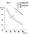
- the combustible gas sensitivity is influenced by the size of the gas sensitive member 12; the sensitivity increases as the size of the member 12 diminishes. For example, if the gas sensitive member 12 is about 0.5 mm in diameter and height, the value of Result 1 achieved by specimen 17 in Table 3 becomes 0.85 to 0.9. This appears attributable to the fact that while the unreacted combustible gas diffuses through the sensitive member 12 of large size, the gas reacts with oxygen and is thereby removed owing to the oxidizing activity of ASnO 3 .
- the value of the above expression corresponds to the spacing between the transient values divided by the spacing between the stationary values.
- Table 4 shows the values of chief specimens at 700 C. Each specimen of the invention is higher in response speed than SnO 2 of the comparative example.
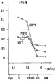
- BaSnO 3 , SrSnO 3 and CaSnO 3 were tested at varying oxygen partial pressures under N 2 balance to determine the relation of the oxygen sensitivity with the specific surface area S, as well as with the mean crystallite size D. The results are shown in Figs. 8 to 10, in which m plotted as ordinate represents oxygen gradient. The results achieved by BaSnO 3 are given in Fig. 8, those by SrSnO 3 in Fig. 9, and those by CaSnO 3 in Fig. 10. Specimen 21 is close to specimen 17 in m value.
- Figs. 8 to 10 show oxygen sensitivities as static characteristics.
- the oxygen sensitivity when measured in a dynamic mode, is lower by an amount corresponding to a deficiency in responsiveness to a change in oxygen partial pressure.
- BaSnO 3 is similar to RaSnO 3 , and SrSnO 3 to CaSnO 3 .
- Ba 1-x Ra x SnO 3 is similar to BaSnO 3 , and Ca 1-x Sr x SnO 3 to CaSnO 3 or SrSnO 3 .
- Table 5 shows the oxygen gradient of Ba 1-x Sr x SnO 3 . It is seen that with respect to the oxygen gradient, the compound is intermediate between BaSnO 3 and SrSn0 3 according to the value of x.
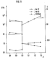
- specimens 17 and 45 were tested as heated at 900° C, with the results shown in F ig. ll.
- the compounds ASn0 3 described above can be used as admixed with other substances. Any substance may be added to ASnO 3 insofar as the characteristics of the gas sensitive member 12 are governed by ASn0 3 .
- the compound ASnO 3 may be used as admixed, for example, with SnO 2 . Since the characteristics of perovskite compounds are insensitive to the replacement of their component elements as already known (e.g. U.S. Patent No. 3,558,280), the element A and Sn element of the compound ASnO 3 may be replaced by other metal elements, each in a proportion of up to 20 mole %, preferably up to 10 mole %, more preferably up to 3 mole %.
Landscapes
- Chemical & Material Sciences (AREA)
- Chemical Kinetics & Catalysis (AREA)
- Electrochemistry (AREA)
- Physics & Mathematics (AREA)
- Health & Medical Sciences (AREA)
- Life Sciences & Earth Sciences (AREA)
- Analytical Chemistry (AREA)
- Biochemistry (AREA)
- General Health & Medical Sciences (AREA)
- General Physics & Mathematics (AREA)
- Immunology (AREA)
- Pathology (AREA)
- Investigating Or Analyzing Materials By The Use Of Fluid Adsorption Or Reactions (AREA)
Applications Claiming Priority (4)
| Application Number | Priority Date | Filing Date | Title |
|---|---|---|---|
| JP63900/84 | 1984-03-30 | ||
| JP63901/84 | 1984-03-30 | ||
| JP6390184A JPS60205343A (ja) | 1984-03-30 | 1984-03-30 | リ−ンバ−ン用の空燃比検出装置 |
| JP6390084A JPS60205342A (ja) | 1984-03-30 | 1984-03-30 | 排ガスセンサおよびその製造方法 |
Publications (3)
| Publication Number | Publication Date |
|---|---|
| EP0157328A2 true EP0157328A2 (de) | 1985-10-09 |
| EP0157328A3 EP0157328A3 (en) | 1986-09-10 |
| EP0157328B1 EP0157328B1 (de) | 1989-03-08 |
Family
ID=26405033
Family Applications (1)
| Application Number | Title | Priority Date | Filing Date |
|---|---|---|---|
| EP85103512A Expired EP0157328B1 (de) | 1984-03-30 | 1985-03-25 | Abgassensor und Verfahren zu dessen Herstellung |
Country Status (3)
| Country | Link |
|---|---|
| US (1) | US4701739A (de) |
| EP (1) | EP0157328B1 (de) |
| DE (1) | DE3568638D1 (de) |
Cited By (4)
| Publication number | Priority date | Publication date | Assignee | Title |
|---|---|---|---|---|
| DE3545372A1 (de) * | 1984-12-20 | 1986-07-03 | Figaro Engineering Inc., Minoo, Osaka | (lambda)-fuehler |
| EP0206236A3 (en) * | 1985-06-24 | 1987-07-22 | Figaro Engineering Inc. | Gas sensor |
| EP0263394A3 (en) * | 1986-09-29 | 1989-02-08 | Figaro Engineering Inc. | A method for producing an exhaust gas sensor |
| WO1992017773A1 (en) * | 1991-04-05 | 1992-10-15 | British Gas Plc | Tin oxide gas sensors |
Families Citing this family (14)
| Publication number | Priority date | Publication date | Assignee | Title |
|---|---|---|---|---|
| JP2632537B2 (ja) * | 1988-03-15 | 1997-07-23 | フィガロ技研株式会社 | ガスセンサ |
| US4880519A (en) * | 1988-05-24 | 1989-11-14 | Gte Laboratories Incorporated | Gas sensor element |
| US4897174A (en) * | 1988-05-24 | 1990-01-30 | Gte Laboratories Incorporated | Gas sensing apparatus |
| JPH02193053A (ja) * | 1988-07-14 | 1990-07-30 | Figaro Eng Inc | 排ガスセンサ及びその製造方法 |
| DE68927087T2 (de) * | 1988-11-01 | 1997-02-06 | Ngk Spark Plug Co | Sauerstoffempfindlicher Sensor und Verfahren zu dessen Herstellung |
| US5345213A (en) * | 1992-10-26 | 1994-09-06 | The United States Of America, As Represented By The Secretary Of Commerce | Temperature-controlled, micromachined arrays for chemical sensor fabrication and operation |
| US6168426B1 (en) | 1996-02-19 | 2001-01-02 | Murata Manufacturing Co., Ltd. | Batch-type kiln |
| JP2920109B2 (ja) * | 1996-04-24 | 1999-07-19 | 大阪瓦斯株式会社 | 窒素酸化物センサー及びその製造方法 |
| US6044689A (en) * | 1997-04-24 | 2000-04-04 | Ngk Insulators, Ltd. | Apparatus for sensing low concentration NOx, chamber used for apparatus for sensing low concentration NOx; gas sensor element and method of manufacturing the same; and ammonia removing apparatus and NOx sensor utilizing this apparatus |
| US6468682B1 (en) | 2000-05-17 | 2002-10-22 | Avista Laboratories, Inc. | Ion exchange membrane fuel cell |
| US6532792B2 (en) | 2001-07-26 | 2003-03-18 | Avista Laboratories, Inc. | Method of compensating a MOS gas sensor, method of manufacturing a MOS gas sensor, MOS gas sensor, and fuel cell system |
| US20040084308A1 (en) * | 2002-11-01 | 2004-05-06 | Cole Barrett E. | Gas sensor |
| US20100078151A1 (en) * | 2008-09-30 | 2010-04-01 | Osram Sylvania Inc. | Ceramic heat pipe with porous ceramic wick |
| US11499467B2 (en) * | 2019-08-12 | 2022-11-15 | Delphi Technologies Ip Limited | Exhaust sensor with high-temperature terminal |
Family Cites Families (8)
| Publication number | Priority date | Publication date | Assignee | Title |
|---|---|---|---|---|
| US3946198A (en) * | 1974-07-01 | 1976-03-23 | Ford Motor Company | Electrical control system for an exhaust gas sensor |
| DE2648373C2 (de) * | 1976-10-26 | 1986-01-02 | Robert Bosch Gmbh, 7000 Stuttgart | Halbleiter für Sensoren zur Bestimmung des Gehaltes an Sauerstoff und/oder oxydierbaren Bestandteilen in Abgasen |
| JPS5518922A (en) * | 1978-07-26 | 1980-02-09 | Fuji Electric Co Ltd | Oxygen sensor |
| US4314996A (en) * | 1979-04-04 | 1982-02-09 | Matsushita Electric Industrial Company, Limited | Oxygen sensor |
| JPS57178147A (en) * | 1981-04-27 | 1982-11-02 | Nippon Soken Inc | Detector for gaseous component |
| JPS58180936A (ja) * | 1982-04-17 | 1983-10-22 | Fuigaro Giken Kk | 燃焼状態検出素子およびその製造方法 |
| JPS5927253A (ja) * | 1982-08-06 | 1984-02-13 | Shinei Kk | ガスセンサおよびその製造法 |
| GB8329003D0 (en) * | 1983-10-31 | 1983-11-30 | Atomic Energy Authority Uk | Sensors |
-
1985
- 1985-03-13 US US06/711,154 patent/US4701739A/en not_active Expired - Lifetime
- 1985-03-25 EP EP85103512A patent/EP0157328B1/de not_active Expired
- 1985-03-25 DE DE8585103512T patent/DE3568638D1/de not_active Expired
Cited By (7)
| Publication number | Priority date | Publication date | Assignee | Title |
|---|---|---|---|---|
| DE3545372A1 (de) * | 1984-12-20 | 1986-07-03 | Figaro Engineering Inc., Minoo, Osaka | (lambda)-fuehler |
| EP0206236A3 (en) * | 1985-06-24 | 1987-07-22 | Figaro Engineering Inc. | Gas sensor |
| US4731226A (en) * | 1985-06-24 | 1988-03-15 | Figaro Engineering Inc. | Gas sensor |
| EP0263394A3 (en) * | 1986-09-29 | 1989-02-08 | Figaro Engineering Inc. | A method for producing an exhaust gas sensor |
| WO1992017773A1 (en) * | 1991-04-05 | 1992-10-15 | British Gas Plc | Tin oxide gas sensors |
| US5427740A (en) * | 1991-04-05 | 1995-06-27 | British Gas Plc | Tin oxide gas sensors |
| EP0806657A3 (de) * | 1991-04-05 | 2001-12-12 | BG plc | Zinnoxidgassensoren |
Also Published As
| Publication number | Publication date |
|---|---|
| EP0157328B1 (de) | 1989-03-08 |
| DE3568638D1 (en) | 1989-04-13 |
| US4701739A (en) | 1987-10-20 |
| EP0157328A3 (en) | 1986-09-10 |
Similar Documents
| Publication | Publication Date | Title |
|---|---|---|
| US4701739A (en) | Exhaust gas sensor and process for producing same | |
| Logothetis et al. | Oxygen sensors using CoO ceramics | |
| US4816800A (en) | Exhaust gas sensor | |
| US4001756A (en) | Measuring cell for determining oxygen concentrations in a gas mixture | |
| EP0001510A1 (de) | Gassensor | |
| US4413502A (en) | Gas detecting sensor | |
| EP0056752A1 (de) | Titandioxid-Sauerstoffsensor mit Chromoxid-Kompensator | |
| EP0197629B1 (de) | Alkoholselektiver Gassensor | |
| US5472591A (en) | Oxygen concentration detector having heat-treated support layer providing high responsivity endurance | |
| US4658632A (en) | Sensor | |
| US4692429A (en) | Catalyst composition and multi-functional sensor | |
| EP0002375B1 (de) | Sauerstoff-Sensor für Motor-Treibstoffzuführungsregelsysteme | |
| GB2096321A (en) | Combustible-gas detectors | |
| US4832818A (en) | Air/fuel ratio sensor | |
| US4961957A (en) | Method of producing an electrochemical cell having a porous electrode or electrodes | |
| GB2166549A (en) | Gas detecting elements and process for producing the same | |
| EP0199761A1 (de) | Sensoren und verfahren zum messen des sauerstoffteildrucks in heissen gasen | |
| US4231254A (en) | Rare earth or yttrium, transition metal oxide thermistors | |
| Howarth et al. | A simple titania thick film exhaust gas oxygen sensor | |
| JP3669807B2 (ja) | 一酸化炭素検出センサー | |
| JPH0417377B2 (de) | ||
| JPH0417376B2 (de) | ||
| CA1133231A (en) | Rare earth or yttrium, transition metal oxide thermistors | |
| JPS6228420B2 (de) | ||
| JP3415677B2 (ja) | ガスセンサ |
Legal Events
| Date | Code | Title | Description |
|---|---|---|---|
| PUAI | Public reference made under article 153(3) epc to a published international application that has entered the european phase |
Free format text: ORIGINAL CODE: 0009012 |
|
| AK | Designated contracting states |
Designated state(s): AT BE CH DE FR GB IT LI LU NL SE |
|
| RBV | Designated contracting states (corrected) |
Designated state(s): DE GB |
|
| PUAL | Search report despatched |
Free format text: ORIGINAL CODE: 0009013 |
|
| AK | Designated contracting states |
Kind code of ref document: A3 Designated state(s): DE GB |
|
| 17P | Request for examination filed |
Effective date: 19860725 |
|
| 17Q | First examination report despatched |
Effective date: 19880722 |
|
| GRAA | (expected) grant |
Free format text: ORIGINAL CODE: 0009210 |
|
| AK | Designated contracting states |
Kind code of ref document: B1 Designated state(s): DE GB |
|
| REF | Corresponds to: |
Ref document number: 3568638 Country of ref document: DE Date of ref document: 19890413 |
|
| PLBE | No opposition filed within time limit |
Free format text: ORIGINAL CODE: 0009261 |
|
| STAA | Information on the status of an ep patent application or granted ep patent |
Free format text: STATUS: NO OPPOSITION FILED WITHIN TIME LIMIT |
|
| 26N | No opposition filed | ||
| PGFP | Annual fee paid to national office [announced via postgrant information from national office to epo] |
Ref country code: GB Payment date: 19960409 Year of fee payment: 12 |
|
| PGFP | Annual fee paid to national office [announced via postgrant information from national office to epo] |
Ref country code: DE Payment date: 19960521 Year of fee payment: 12 |
|
| PG25 | Lapsed in a contracting state [announced via postgrant information from national office to epo] |
Ref country code: GB Effective date: 19970325 |
|
| GBPC | Gb: european patent ceased through non-payment of renewal fee |
Effective date: 19970325 |
|
| PG25 | Lapsed in a contracting state [announced via postgrant information from national office to epo] |
Ref country code: DE Effective date: 19971202 |