EP0157882A1 - Numerische steuervorrichtung - Google Patents
Numerische steuervorrichtung Download PDFInfo
- Publication number
- EP0157882A1 EP0157882A1 EP84903564A EP84903564A EP0157882A1 EP 0157882 A1 EP0157882 A1 EP 0157882A1 EP 84903564 A EP84903564 A EP 84903564A EP 84903564 A EP84903564 A EP 84903564A EP 0157882 A1 EP0157882 A1 EP 0157882A1
- Authority
- EP
- European Patent Office
- Prior art keywords
- display
- time
- information
- displayed
- input
- Prior art date
- Legal status (The legal status is an assumption and is not a legal conclusion. Google has not performed a legal analysis and makes no representation as to the accuracy of the status listed.)
- Granted
Links
Images


Classifications
-
- G—PHYSICS
- G05—CONTROLLING; REGULATING
- G05B—CONTROL OR REGULATING SYSTEMS IN GENERAL; FUNCTIONAL ELEMENTS OF SUCH SYSTEMS; MONITORING OR TESTING ARRANGEMENTS FOR SUCH SYSTEMS OR ELEMENTS
- G05B19/00—Program-control systems
- G05B19/02—Program-control systems electric
- G05B19/18—Numerical control [NC], i.e. automatically operating machines, in particular machine tools, e.g. in a manufacturing environment, so as to execute positioning, movement or co-ordinated operations by means of program data in numerical form
- G05B19/414—Structure of the control system, e.g. common controller or multiprocessor systems, interface to servo, programmable interface controller
- G05B19/4147—Structure of the control system, e.g. common controller or multiprocessor systems, interface to servo, programmable interface controller characterised by using a programmable interface controller [PIC]
-
- G—PHYSICS
- G05—CONTROLLING; REGULATING
- G05B—CONTROL OR REGULATING SYSTEMS IN GENERAL; FUNCTIONAL ELEMENTS OF SUCH SYSTEMS; MONITORING OR TESTING ARRANGEMENTS FOR SUCH SYSTEMS OR ELEMENTS
- G05B2219/00—Program-control systems
- G05B2219/10—Plc systems
- G05B2219/11—Plc I-O input output
- G05B2219/1178—Display states of I-O in time
-
- G—PHYSICS
- G05—CONTROLLING; REGULATING
- G05B—CONTROL OR REGULATING SYSTEMS IN GENERAL; FUNCTIONAL ELEMENTS OF SUCH SYSTEMS; MONITORING OR TESTING ARRANGEMENTS FOR SUCH SYSTEMS OR ELEMENTS
- G05B2219/00—Program-control systems
- G05B2219/30—Nc systems
- G05B2219/33—Director till display
- G05B2219/33297—Diagnostic, test, debug
Definitions
- This invention relates to a numerical control system employable for controlling machine tools and the like. More specifically, this invention relates to a numerical control system having a function to graphically display the sequential progress or operational positions of any of the control elements controlled by the numerical control system, in an arbitrarily selected manner in terms of e.g. display format, time scale (which is defined as a length of time to be represented by a unit geometrical length of a display), display starting time, or the like.
- display format which is defined as a length of time to be represented by a unit geometrical length of a display
- time scale which is defined as a length of time to be represented by a unit geometrical length of a display
- display starting time or the like.
- the essential components of a numerical control system are a central processing unit, a memory means and an input-output means.
- a display means is not necessarily included in the essential components of a numerical control system, the display means is extremely convenient for finding various errors caused by user's operations and/or various errors relating to the items of user's operations e.g. a program error, a control error, et al. and/or for finding misoperations of the numerical control system proper.
- the display means is useful for monitoring the sequential progress of machining conducted by a machine tool controlled by a numerical control system. ;ince a display means is thus significant for a numerical control system, a numerical control system is usually equipped with a display means. Particularly, the items relating to user's operations are preferably displayed.
- a programmable controller is preferably employed for the sequential control unit of a power panel which functions as the interface connecting a numerical control system and a machine tool controlled therewith, because it is convenient for compiling and testing a program e.g. a sequential control program or the like.
- a programmable controller is defined as an additional computer consisting of a processing unit, a memory means, and an input-output means in some cases, and of which the purpose is to supplement the function of a principal computor which the programmable controller is attached to.
- the programmable controller is inputted various information including the information which a user inputs in an input-output means of a computor, the information picked up by a sensor attached to a machine tool controlled with a numerical control system, the information inputted by a numerical control system.
- the information inputted to this programmable controller is processed following the program of the programmable controller, before the results of the processing are inputted to the numerical control system and/or the machine tool.
- a programmable controller is a supplemental computor having an individual specification and being designed and installed independently of a numerical control system which is inclined to have a fixed or non-flexible specification due to the potential advantage of mass production, and it has a function to apply preparatory processes to the information predominantly relating to user's operations and to input the results of the preparatory processes to a numerical control system and/or a maching tool. Accordingly, a means for displaying the information inputted and/or outputted by a programmable controller, causes a considerable grade of advantage.
- This invention relates to an improvement applicable to a display means which is attached to a numerical control system with which a programmable controller is employed.
- a numerical control system having a programmable controller and a display means, uses numerals as media for displaying control elements.
- numerals are arranged in the format of a program list, it is generally difficult to display the sequential progress or operational positions of plural control elements which relate to one another in one picture.
- a display means having functions itemized below is extremely useful from the industrial viewpoints, if such a display is available :
- the object of this invention is to provide a numerical control system having a display means having the functions itemized below :
- the input-output means, the processing unit and the display means of a numerical control system provided a programmable controller in accordance with this invention, are as shown below :
- the aforementioned information elements are graphically displayed, based on the conditions determind by the aforementioned processing unit.
- the information input-output means 3 is provided (a) a means 31 for inputting the address numbers of a plurality of information elements to be displayed, (b) a means 32 for inputting the time scale (which is defined as a length of time to be represented by a unit geometrical length of a display) with which a display is presented, (c) a means 33 for inputting the address number of a display trigger information element, (d) a means 34 for inputting a command for selection of either a set of repetitive pictures or a one-shot type picture, and (e) a means 35 for inputting the delay time for which the commencement of display is delayed after the correseponding trigger signal is issued.
- the time scale which is defined as a length of time to be represented by a unit geometrical length of a display
- the programmable controller 5 is a compact computor provided with a processing unit and a memory means and which is loaded with a program of its own, so that it conducts calculation based on its own program, for any of the information including the information inputted by the input- output means 3, the signals detected by the machine tool 6 to be controlled by the numerical control system and the signals given by the processing unit 1, before it outputs the results of the calculation toward the machine tool 6 and the processing unit 1.
- the programable controller 5 has functions for compiling, testing, and the like of the programs for sequence control et al.
- the processing unit 1 is provided (a) a means 11 for selecting the address numbers of a plurality of information elements to be displayed, (b) a means 12 for selecting the time scale (which is defined as a length of time to be represented by a unit geometrical length of a display) with which a display is presented, (c) a means 13 for selecting the address number of a display trigger information element, (d) a means 14 for conducting a command for selection of either repetitive display or one-shot type display, and (e) a means 15 for selecting the delay time for which the commencement of display is delayed after the corresponding trigger signal is issued. So that these selections and commands can be conducted.
- the picture frame or screen of the display means 4 is provided (a) an area 41 in which the address numbers of a plurality of information elements to be displayed are displayed, (b) an area 42 in which the sequential progress or operational positions of the information elements is graphically displayed, and (c) an area 43 in which the display conditions are displayed, so that each of the aforementioned display elements is displayed in each display area described above.
- a display means having functions itemized below :
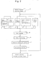
- Fig. 2 (a flow chart illustrating the operation procedure), the operation procedure of this numerical control system in accordance with one embodiment of this invention, will be described below.
- a display picture frame selection switch is turned on to select a display picture frame (a).
- the address numbers of all the information elements which are desired to be displayed are inputted (b).
- the maximum quantity of information elements which can be simultaneously displayed is detemined by the dimension of the display means.
- the time scale (which is defined as a length of time to be represented by a unit geometrical length of a display) shown in terms of second, is inputted (c).
- the time scale is intended to mean a time-wise scale or unit following which the time-wise dimension of a display is determined.
- the time scale is intended to mean the length of time corresponding to the geometrical length of the intervals left among the scratches shown at the top line in Fig. 4.
- the address number of an information element which is selected as a trigger element is inputted.
- the trigger element can be selected out of all the control elements available (d).
- a command for selecting either a set of repetitive pictures or a one-shot type picture is inputted (e). If the former is selected, a picture cyclically appears for a set of information elements, whenever the selected trigger signal is cyclically issued following the programmed sequence. In contrast, if the latter is selected, a picture representing the operational positions corresponding to the time at which a trigger signal is issued,
- a start switch is turned on to start the processing unit 1 (g).
- a machine tool starts machining (h).
- a reset switch is turned on to initialize the screen (j).
- a display picture frame selection switch is turned on again to select another display picture frame (k).
- An examination is conducted to determine whether or not a rising trigger is selected (c'). If it is not selected, the progress is paused until the trigger address informaiton shifts to an L level from a H level (d'). If a rising trigger is selected, the progress is paused until the trigger address information shifts to a H level from an L level (e'). In other words, if a rising trigger is selected, the progress proceeds, provided the trigger address information shifts from an L level to a H level, and if a rising trigger is not selected, the progress proceeds, provided the trigger address information shifts from a H level to an L level.
- a No.1 timer which is to set the period between the commencement of a trigger and the commencement of reading binary information, starts the time counting operation (g'). The timer is set by means of an input means of the delay time for reading. The progress is paused until the No.1 timer finishes the time counting operation (h'). In contrast, if no delay time is inputted, this step is skipped.
- the number of times N calculated in the b' step is set on'a No.1 register, which is a register on which the number of times representing the difference between the number of times for reading binary information and the number of times representing the number of times which have already been read (i').
- No.2 timer (a timer which determines the period remained for reading binary information and of which the set time is fixed in the processing unit 1) starts the time counting operation (I').
- the binary information of the selected address is read (m'), and the displayed content is revised (n').
- the progress is paused until the No.2 timer finishes the time counting operation (o'). Provided the NO.2 timer finishes the time counting operation, the progress returns to the j ' step.
- No.1 register is not larger than "0 (zero)" (j')
- a No.3 timer (a timer which determines the duration period in which a position representing the termination of a display is kept and of which the set time is fixed in the processing unit 1) starts the time counting operation (q').
- the progress is paused until a reset switch is turned on (w').
- FIG. 4 An exemplary picture appearing on the screen of the display means 4 is illustrated in Fig. 4. Referring to Fig. 4, the displayed information is as follows :
- the area 41 displays the address numbers of the information elements to be displayed and the identification of levels (H or L) for the graphich display showing the sequential progress or operational positions of the aforementioned information elements which are displayed in the area 42.
- the area 43 displays the display conditions.
Landscapes
- Engineering & Computer Science (AREA)
- Human Computer Interaction (AREA)
- Manufacturing & Machinery (AREA)
- Physics & Mathematics (AREA)
- General Physics & Mathematics (AREA)
- Automation & Control Theory (AREA)
- Numerical Control (AREA)
Applications Claiming Priority (2)
| Application Number | Priority Date | Filing Date | Title |
|---|---|---|---|
| JP58177043A JP2544593B2 (ja) | 1983-09-27 | 1983-09-27 | 数値制御装置 |
| JP177043/83 | 1983-09-27 |
Publications (3)
| Publication Number | Publication Date |
|---|---|
| EP0157882A1 true EP0157882A1 (de) | 1985-10-16 |
| EP0157882A4 EP0157882A4 (de) | 1988-04-26 |
| EP0157882B1 EP0157882B1 (de) | 1991-01-30 |
Family
ID=16024136
Family Applications (1)
| Application Number | Title | Priority Date | Filing Date |
|---|---|---|---|
| EP84903564A Expired EP0157882B1 (de) | 1983-09-27 | 1984-09-25 | Numerische steuervorrichtung |
Country Status (5)
| Country | Link |
|---|---|
| US (1) | US4661899A (de) |
| EP (1) | EP0157882B1 (de) |
| JP (1) | JP2544593B2 (de) |
| DE (1) | DE3484061D1 (de) |
| WO (1) | WO1985001595A1 (de) |
Cited By (5)
| Publication number | Priority date | Publication date | Assignee | Title |
|---|---|---|---|---|
| GB2187308A (en) * | 1986-02-27 | 1987-09-03 | Mitsubishi Electric Corp | An operation program checking method for a numerical control device |
| GB2266167A (en) * | 1992-04-15 | 1993-10-20 | Toshiba Kk | Communication system and method for communicating data |
| GB2284075A (en) * | 1993-03-31 | 1995-05-24 | Mitsubishi Electric Corp | Programmable controller and methods of setting and displaying its internal information |
| US5471380A (en) * | 1993-03-31 | 1995-11-28 | Mitsubishi Denki Kabushiki Kaisha | Programmable controller and methods of setting and displaying its internal information |
| US20150362912A1 (en) * | 2014-06-13 | 2015-12-17 | Fanuc Corporation | Numerical control system |
Families Citing this family (10)
| Publication number | Priority date | Publication date | Assignee | Title |
|---|---|---|---|---|
| JPS62119608A (ja) * | 1985-11-20 | 1987-05-30 | Fanuc Ltd | 対話形プログラミング装置 |
| US5276811A (en) * | 1989-06-30 | 1994-01-04 | Icom, Inc. | Method for emulating programmable logic controller by exchanging information between debug program which emulates I/O devices and ladder logic program |
| US4991076A (en) * | 1989-06-30 | 1991-02-05 | Icom Inc. | Method and apparatus for creating custom displays for monitoring ladder logic programs |
| US5243511A (en) * | 1989-06-30 | 1993-09-07 | Icom, Inc. | Method and apparatus for block move re-addressing in ladder logic programs |
| US5349518A (en) * | 1989-06-30 | 1994-09-20 | Icom, Inc. | Method and apparatus for symbolic ladder logic programming with automatic attachment of addresses |
| US5267145A (en) * | 1989-06-30 | 1993-11-30 | Icom, Inc. | Method and apparatus for program navigation and editing for ladder logic programs by determining which instructions reference a selected data element address |
| US5127099A (en) * | 1989-06-30 | 1992-06-30 | Icom, Inc. | Method and apparatus for securing access to a ladder logic programming and monitoring system |
| US5132716A (en) * | 1990-04-04 | 1992-07-21 | Eastman Kodak Company | System for updating software in automatic film processor |
| US5321829A (en) * | 1990-07-20 | 1994-06-14 | Icom, Inc. | Graphical interfaces for monitoring ladder logic programs |
| US5392226A (en) * | 1993-06-17 | 1995-02-21 | Icom, Inc. | Computer-implemented method and apparatus for monitoring statistical process control data |
Family Cites Families (17)
| Publication number | Priority date | Publication date | Assignee | Title |
|---|---|---|---|---|
| JPS5612884B2 (de) * | 1974-03-26 | 1981-03-25 | ||
| JPS53117181A (en) * | 1977-03-23 | 1978-10-13 | Sharp Corp | Sequence controller |
| JPS53139074A (en) * | 1977-05-10 | 1978-12-05 | Toshiba Corp | Numerical control device |
| JPS55938A (en) * | 1978-06-19 | 1980-01-07 | Toshiba Corp | Online monitor unit of sequnce controller |
| JPS6122381Y2 (de) * | 1979-05-15 | 1986-07-04 | ||
| US4445182A (en) * | 1979-10-02 | 1984-04-24 | Daihatsu Motor Company, Limited | Method of control of NC machine tools |
| JPS5663612A (en) * | 1979-10-30 | 1981-05-30 | Toshiba Corp | Controller with process fault diagnostic function |
| DE2950102C2 (de) * | 1979-12-13 | 1982-09-02 | Institut für Rundfunktechnik GmbH, 8000 München | Einrichtung zum visuellen Überwachen eines Prozeßablaufs |
| JPS57120117A (en) * | 1981-01-17 | 1982-07-27 | Mitsubishi Electric Corp | Regenerating device |
| JPS57162001A (en) * | 1981-03-31 | 1982-10-05 | Toshiba Corp | Displaying method of cathode-ray tube display device |
| JPS57176424A (en) * | 1981-04-24 | 1982-10-29 | Hitachi Ltd | System failure alarming system |
| JPS5819910A (ja) * | 1981-07-28 | 1983-02-05 | Omron Tateisi Electronics Co | プログラマブル・コントロ−ラのモニタ表示方式 |
| JPS5854405A (ja) * | 1981-09-26 | 1983-03-31 | Toshiba Corp | プラント監視方法 |
| JPS5899803A (ja) * | 1981-12-09 | 1983-06-14 | Mitsubishi Electric Corp | 数値制御装置 |
| JPS58155147A (ja) * | 1982-03-04 | 1983-09-14 | Mitsubishi Electric Corp | 数値制御加工方式 |
| JPS58151609A (ja) * | 1982-03-05 | 1983-09-08 | Toshiba Corp | 計算機によるプラント自動運転操作の進行状態表示方法 |
| JPS5995610A (ja) * | 1982-11-22 | 1984-06-01 | Fanuc Ltd | 状態表示部を備えた制御装置 |
-
1983
- 1983-09-27 JP JP58177043A patent/JP2544593B2/ja not_active Expired - Lifetime
-
1984
- 1984-09-25 US US06/744,007 patent/US4661899A/en not_active Expired - Fee Related
- 1984-09-25 EP EP84903564A patent/EP0157882B1/de not_active Expired
- 1984-09-25 WO PCT/JP1984/000458 patent/WO1985001595A1/ja not_active Ceased
- 1984-09-25 DE DE8484903564T patent/DE3484061D1/de not_active Expired - Lifetime
Cited By (12)
| Publication number | Priority date | Publication date | Assignee | Title |
|---|---|---|---|---|
| GB2187308A (en) * | 1986-02-27 | 1987-09-03 | Mitsubishi Electric Corp | An operation program checking method for a numerical control device |
| GB2187308B (en) * | 1986-02-27 | 1990-03-07 | Mitsubishi Electric Corp | Operation program checking method for a numerical control device |
| GB2266167A (en) * | 1992-04-15 | 1993-10-20 | Toshiba Kk | Communication system and method for communicating data |
| GB2266167B (en) * | 1992-04-15 | 1995-08-16 | Toshiba Kk | Communicating system and method for communicating data |
| US5467078A (en) * | 1992-04-15 | 1995-11-14 | Kabushiki Kaisha Toshiba | System and method for communicating data between plural air conditioning machines for controlling the machines and displaying their status |
| GB2284075A (en) * | 1993-03-31 | 1995-05-24 | Mitsubishi Electric Corp | Programmable controller and methods of setting and displaying its internal information |
| US5471380A (en) * | 1993-03-31 | 1995-11-28 | Mitsubishi Denki Kabushiki Kaisha | Programmable controller and methods of setting and displaying its internal information |
| GB2284075B (en) * | 1993-03-31 | 1996-05-15 | Mitsubishi Electric Corp | Programmable conroller and methods of setting and displaying its internal information |
| GB2276733B (en) * | 1993-03-31 | 1996-05-22 | Mitsubishi Electric Corp | programmable controller and methods of setting and displaying its internal information |
| US5666282A (en) * | 1993-03-31 | 1997-09-09 | Mitsubishi Denki Kabushiki Kaisha | Programmable controller and methods of setting and displaying its internal information |
| US20150362912A1 (en) * | 2014-06-13 | 2015-12-17 | Fanuc Corporation | Numerical control system |
| US9791850B2 (en) * | 2014-06-13 | 2017-10-17 | Fanuc Corporation | Numerical control system |
Also Published As
| Publication number | Publication date |
|---|---|
| EP0157882B1 (de) | 1991-01-30 |
| WO1985001595A1 (en) | 1985-04-11 |
| JPS6069707A (ja) | 1985-04-20 |
| DE3484061D1 (de) | 1991-03-07 |
| EP0157882A4 (de) | 1988-04-26 |
| US4661899A (en) | 1987-04-28 |
| JP2544593B2 (ja) | 1996-10-16 |
Similar Documents
| Publication | Publication Date | Title |
|---|---|---|
| EP0157882A1 (de) | Numerische steuervorrichtung | |
| US4115853A (en) | Jump structure for a digital control system | |
| US5323325A (en) | Method of displaying an operation history of a machine | |
| US5889669A (en) | Programmable controller allowing an external peripheral device to monitor an internal operation state of a CPU unit | |
| EP0173745A4 (de) | Werkzeug-sichtanzeigesystem für einen automatischen werkzeugwechsler. | |
| EP0093229B1 (de) | Vorrichtung und Verfahren zum Testen | |
| US4385367A (en) | Sequence block display system | |
| JPH07191717A (ja) | 制御プログラム自動作成装置 | |
| US5191538A (en) | Apparatus for displaying operation sequence of numerically controlled machine tool | |
| US4924403A (en) | Numerical control method and system therefor having override playback function | |
| EP0362392A1 (de) | Rechnersimulierungssystem | |
| GB2054471A (en) | A freely assignable keyboard | |
| JPH1185446A (ja) | トレンドグラフの表示方法 | |
| US4601009A (en) | Memory system and accessing method | |
| KR840001466A (ko) | 산업 로보트용 제어장치 및 방법 | |
| EP0483368A1 (de) | Suchverfahren eines folgesteuerungsprogramms | |
| JPH0774966B2 (ja) | ロボット操作器の編集装置 | |
| EP0402483A4 (en) | Control method for robot | |
| JP2786737B2 (ja) | プロセス表示装置 | |
| SU1697074A1 (ru) | Устройство дл отображени информации на экране электронно-лучевой трубки | |
| JPH0413624Y2 (de) | ||
| JPS6132106A (ja) | プログラマブルコントロ−ラのプログラミング装置 | |
| EP0140978A4 (de) | Vorrichtung zum anzeigen eines teils eines auf einer spezifischen adresse gespeicherten numerischen steuerprogramms. | |
| JPH0774965B2 (ja) | ロボット操作器の表示装置 | |
| JPH06201413A (ja) | センサ駆動装置 |
Legal Events
| Date | Code | Title | Description |
|---|---|---|---|
| PUAI | Public reference made under article 153(3) epc to a published international application that has entered the european phase |
Free format text: ORIGINAL CODE: 0009012 |
|
| 17P | Request for examination filed |
Effective date: 19850528 |
|
| AK | Designated contracting states |
Designated state(s): DE FR GB |
|
| A4 | Supplementary search report drawn up and despatched |
Effective date: 19880426 |
|
| 17Q | First examination report despatched |
Effective date: 19891206 |
|
| GRAA | (expected) grant |
Free format text: ORIGINAL CODE: 0009210 |
|
| AK | Designated contracting states |
Kind code of ref document: B1 Designated state(s): DE FR GB |
|
| REF | Corresponds to: |
Ref document number: 3484061 Country of ref document: DE Date of ref document: 19910307 |
|
| ET | Fr: translation filed | ||
| PGFP | Annual fee paid to national office [announced via postgrant information from national office to epo] |
Ref country code: FR Payment date: 19910904 Year of fee payment: 8 |
|
| PGFP | Annual fee paid to national office [announced via postgrant information from national office to epo] |
Ref country code: GB Payment date: 19910913 Year of fee payment: 8 |
|
| PLBI | Opposition filed |
Free format text: ORIGINAL CODE: 0009260 |
|
| 26 | Opposition filed |
Opponent name: ROBERT BOSCH GMBH Effective date: 19911029 |
|
| PG25 | Lapsed in a contracting state [announced via postgrant information from national office to epo] |
Ref country code: GB Effective date: 19920925 |
|
| GBPC | Gb: european patent ceased through non-payment of renewal fee |
Effective date: 19920925 |
|
| PG25 | Lapsed in a contracting state [announced via postgrant information from national office to epo] |
Ref country code: FR Effective date: 19930528 |
|
| REG | Reference to a national code |
Ref country code: FR Ref legal event code: ST |
|
| APAC | Appeal dossier modified |
Free format text: ORIGINAL CODE: EPIDOS NOAPO |
|
| PLBN | Opposition rejected |
Free format text: ORIGINAL CODE: 0009273 |
|
| STAA | Information on the status of an ep patent application or granted ep patent |
Free format text: STATUS: OPPOSITION REJECTED |
|
| PGFP | Annual fee paid to national office [announced via postgrant information from national office to epo] |
Ref country code: DE Payment date: 19961004 Year of fee payment: 13 |
|
| 27O | Opposition rejected |
Effective date: 19950515 |
|
| PG25 | Lapsed in a contracting state [announced via postgrant information from national office to epo] |
Ref country code: DE Free format text: LAPSE BECAUSE OF NON-PAYMENT OF DUE FEES Effective date: 19980603 |
|
| APAH | Appeal reference modified |
Free format text: ORIGINAL CODE: EPIDOSCREFNO |