EP0160343A2 - Machine de formage d'anneaux extérieurs pour pièces de monnaie ou médailles bimétalliques à partir d'ébauches métalliques rondes - Google Patents
Machine de formage d'anneaux extérieurs pour pièces de monnaie ou médailles bimétalliques à partir d'ébauches métalliques rondes Download PDFInfo
- Publication number
- EP0160343A2 EP0160343A2 EP85200652A EP85200652A EP0160343A2 EP 0160343 A2 EP0160343 A2 EP 0160343A2 EP 85200652 A EP85200652 A EP 85200652A EP 85200652 A EP85200652 A EP 85200652A EP 0160343 A2 EP0160343 A2 EP 0160343A2
- Authority
- EP
- European Patent Office
- Prior art keywords
- die
- punch
- machine
- backing
- blank
- Prior art date
- Legal status (The legal status is an assumption and is not a legal conclusion. Google has not performed a legal analysis and makes no representation as to the accuracy of the status listed.)
- Granted
Links
Images



Classifications
-
- B—PERFORMING OPERATIONS; TRANSPORTING
- B21—MECHANICAL METAL-WORKING WITHOUT ESSENTIALLY REMOVING MATERIAL; PUNCHING METAL
- B21D—WORKING OR PROCESSING OF SHEET METAL OR METAL TUBES, RODS OR PROFILES WITHOUT ESSENTIALLY REMOVING MATERIAL; PUNCHING METAL
- B21D53/00—Making other particular articles
- B21D53/16—Making other particular articles rings, e.g. barrel hoops
-
- B—PERFORMING OPERATIONS; TRANSPORTING
- B44—DECORATIVE ARTS
- B44B—MACHINES, APPARATUS OR TOOLS FOR ARTISTIC WORK, e.g. FOR SCULPTURING, GUILLOCHING, CARVING, BRANDING, INLAYING
- B44B5/00—Machines or apparatus for embossing decorations or marks, e.g. embossing coins
-
- B—PERFORMING OPERATIONS; TRANSPORTING
- B44—DECORATIVE ARTS
- B44B—MACHINES, APPARATUS OR TOOLS FOR ARTISTIC WORK, e.g. FOR SCULPTURING, GUILLOCHING, CARVING, BRANDING, INLAYING
- B44B5/00—Machines or apparatus for embossing decorations or marks, e.g. embossing coins
- B44B5/02—Dies; Accessories
- B44B5/024—Work piece loading or discharging arrangements
-
- B—PERFORMING OPERATIONS; TRANSPORTING
- B44—DECORATIVE ARTS
- B44B—MACHINES, APPARATUS OR TOOLS FOR ARTISTIC WORK, e.g. FOR SCULPTURING, GUILLOCHING, CARVING, BRANDING, INLAYING
- B44B5/00—Machines or apparatus for embossing decorations or marks, e.g. embossing coins
- B44B5/02—Dies; Accessories
- B44B5/026—Dies
Definitions
- This invention ielates to a machine for forming rings to constitute an outer rim on bimetallic coins or medals, starting from round metal blanks.
- bimetallic coin constituted by an outer steel ring and an inner disc composed of a bronze, cupronickel and aluminium alloy.
- This coin is formed in two stages, namely a first stage in which a round metal blank is used to form the outer ring, which is worked in such a manner as to comprise a compressed and toothed inner annular edge and having its radial cross-section tapering inwards, and a second actual coining stage in which the disc is placed inside the ring and, on being struck by the coining die, expands so that its outer annular edge copenetrates the toothed inner annular edge of the ring, so that these two parts of the coin become securely joined to each other.
- the first stage is carried out by a machine which in a single operation simultaneously both punches out the central portion of the round blank and forms the said compressed and toothed inner edge.
- the backing die has an axial hole which slidably receives the punch.
- the die correspondingly comprises an axial hole designed to receive the punch during the punching and formation of the inner edge of the ring.
- the die and backing die each comprise, at one mouth of the respective hole, a surface in the shape of a circular rim which is designed to come into contact with the round blank. This surface comprises a projecting annular lip which in practice is a continuation of the walls of the hole.
- the walls of each hole also comprise an equal series of longitudinal projecting ribs which terminate at the lip, and the outer cylindrical surface of the punch comprises a corresponding series of longitudinal hollow grooves.
- the round blank When in operation, the round blank is rested on the circular rim- shaped surface of the die.
- the upper support is then made to descend onto the lower support so that the die and backing die lock the round blank between them, the punch passes through the central portion of the round blank so punching it out, and finally an abutment element rigid with the punch presses the die and backing die against each other.
- the central hole is formed in the ring during the punching operation, while the subsequent compression results in the formation of the compressed and toothed edge of the ring by the action of the lips and grooves.
- the shape of the die and backing die does not lend to automatic extraction of the formed ring, which in many cases regains adhering to said elements. This requires manual intervention by suitable pincers, creating serious safety problems besides slowing down the production rate.
- the scrap is constituted by a disc punched from the round blank and comprising notches formed by the ribbing on the die.
- the presence of the notches means that the scrap cannot be used directly for forming a normal small metal coin. The scrap can therefore only be melted down.
- the object of the present invention is to provide a machine with characteristics such as to obviate the aforesaid problems of the current machines.
- the machine according to the invention illustrated in Figure 1 is substantially composed of a feed and advancement unit for the round metal blank, and a punching and precoining unit which actually works the round metal blank carried by the feed and advancement unit until an outer ring for a bimetallic coin or medal is obtained.
- the reference numeral 10 indicates the round metal blank to be worked and 100 the outer ring obtained.
- the feed and advancement unit comprises a chute 11 fed continuously with round metal blanks 10.
- the chute 11 terminates over a cylindrical container 12 in which the blanks 10 arriving from the chute 11 become piled one on the other.
- the container 12 is open at its base to allow the entry of a slider 13 mobile with reciprocating horizontal rectilinear motion, and the exit of an individual metal blank 10.
- the slider 13 enters the container 12 and urges the most lower blank 10 of the pile out of the container 12.
- the slider 13 leaves the container 12 to cause the overlying pile of blanks 10 to fall and a new blank 10 to come into alignment with the outlet of the container 12.
- the slider 13 pushes the blanks 10 one by one, as seen, along a guide 14 disposed in a position corresponding with the punching and precoining unit, as described hereinafter.
- a second chute 15 At the end of the guide 14 there is provided a second chute 15 by means of which the produced outer rings 100 are conveyed away from the machine.
- the punching and precoining unit has a basic structure analogous to that of a vertical press. It comprises a punching station 16 and a precoining station 17.
- a base 18 is provided on which a lower support 19 is rigidly fixed.
- the support 19 carries a die 20 of the punching station 16 and a die 21 of the precoining station 17.
- a slide 22 to which a support 23 is rigidly fixed.
- the support 23 carries an assenbly consisting of a punch, blank-holding backing die and centering element, this assembly being indicated overall by 24 and forming part of the punching station 16.
- the support 23 In a position corresponding with the die 21, the support 23 also carries a punch/backing-die assembly indicated overall by 25 and forming part of the precoining station 17.
- the slide 22 is driven with vertical reciprocating rectilinear motion by a crank cam, not shown because of known type, by way of a connecting rod 26.
- the crank cam is also used for providing the horizontal reciprocating rectilinear motion to the slider 13, as indicated diagrammatically by dashed and dotted lines, so as to synchronise the movement of the punching and precoining unit with the movement of the slider 13.
- the guide 14 runs between the upper assemblies 24 and 25 and the lower dies 20 and 21.
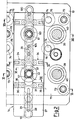
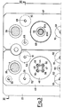
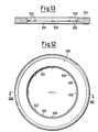
- Figures 2 to 11 show structural and operational details of the machine of Figure 1 which has been described briefly heretofore.
- the guide 14 is substantially constituted by a composite plate 27 of a certain thickness, within which there is provided a longitudinal channel 25 in which the round blanks 10 to be worked are contained and slide in.a row.
- the plate 27 also comprises longitudinal through slots 29 which open into the channel 28 to allow visual checking of the advancement of the blanks 10.
- the plate 27 comprises a lower hole 30 and an upper hole 31 coaxial with the hole 30, these opening into the channel 28.
- the plate 27 comprises a lower hole 32 and an upper hole 33 coaxial with the hole 32, these opening into the channel 28.
- the plate 27 comprises a series of pairs of opposing transverse elastic pushers 34.
- Each elastic pusher 34 is composed of an element 35 slidably housed in a transverse seat 36 of the plate 27, which at one end rotatably carries a wheel 37 and at its other end is urged by a spring 38.
- the spring 38 maintains the element 35 in a position in which the wheel 37 carried by it projects into the channel 28.
- the mobile upper support 23 is guided in its movement by four vertical columns 39 fixed to the support 23 and slidably housed in corresponding bushes 40 inserted into the fixed lower support 19.
- the die 20 is mounted on a block 41 fixed to the fixed lower support 19.
- the die 20 is of substantially cylindrical shape and comprises a circular axial through cavity 42 and a tapered upper mouth 43 with its edge in the form of a flat ring.
- the mouth 43 is housed in the lower hole 30 of the plate 27.
- the assembly 24 comprises, aligned with the cavity 42 of the die 20, a cylindrical punch 44 which has its working end flat and is fixed at its other end to a base 45 rigid with the support 23.
- the assembly 24 also comprises a blank-holding backing die 46 with a cylindrical through cavity 47, in which the punch 44 is slidably housed, and a mouth 48 with its edge in the form of a flat ring which mates with and faces the mouth 43 of the die 20.
- the backing die 46 is fixed to a plate 49 which is slidably mounted on a pair of columns 3? and suspended from the support 23 by tie rods 50 and tie rods 51. Over each tie rod 51 there is mounted a shock absorber block 52 which is interposed between the plate 49 and support 23.
- the assembly 24 comprises a centering retainer 53 constituted by a ring 54 which is kept elastically resting on an inner portion of the backing die 46 by springs 55 acting on the base 45, and to which there are annularly fixed four claws 56 which extend parallel to the punch 44 and external to it towards the plate 27, to pass through the backing die 46.
- a centering retainer 53 constituted by a ring 54 which is kept elastically resting on an inner portion of the backing die 46 by springs 55 acting on the base 45, and to which there are annularly fixed four claws 56 which extend parallel to the punch 44 and external to it towards the plate 27, to pass through the backing die 46.
- the plate 27 there are provided four corresponding cavities 57 -( Figure 2) which open into the channel 28 and are designed to receive the terminal portions of the claws 56.
- the die 21 is mounted on a block 58 fixed to the fixed lower support 19.
- the die 21 is of substantially cylindrical shape and comprises an axial circular through cavity 59 and a tapered upper mouth 60.
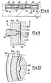
- the mouth 60 has an edge in the form of a flat ring with an internal projecting lip 61 (well visible in the enlargement of Figure 9).
- the mouth 60 comprises longitudinal ribs 62 on its inner annular wall.
- the mouth 60 is housed in the lower hole 32 of the plate 27.
- the assembly 25 comprises, aligned with the cavity 59 of the die 21, a cylindrical punch 63 which is pointed at one end and is fixed at its other end to a base 64 rigid with the support 23.
- the cylindrical outer surface of the punch 63 comprises longitudinal grooves 65 in positions exactly corresponding with the ribs 62 of the die 21.
- the assembly 25 also comprises a backing die identical to the die 21, and which is therefore indicated overall and in its component parts by the same reference numerals as the die 21 followed by the letter A.
- the cylindrical cavity 59A of the backing die 21A slidably houses the punch 63.
- the backing die 21A is mounted in a block 6G, which itself is fixed to a plate 67.
- the plate 67 is mounted slidablc on a pair of columns 39, different from the pair on which the plate 49 is mounted.
- the plate 67 is also supported by the support 23 by means of respective tie rods 68 and 69.
- the plate 27 is elastically suspended with respect to the blocks 41 and 58 of the dies 20 and 21 respectively ( Figure 5). This is obtained by supporting the plate 27 by a plate 71 which is slidably mounted on the columns 39 and rests on springs 72 acting on the support 19. Each spring 72 cooperates with a tie rod 73 which retains the plate 71 by opposing the elastic thrust of the spring. .Finally, stop elements 74 are provided ( Figure 11), each mounted on the fixed lower support 19 by means of a tie rod 75, and with a shock absorber block 76 therebetween. The stop elements 74 are disposed in positions corresponding with the plate 67 in order to brake and halt its downward path of travel.
- each round blank 10 passes stepwise along the guide 28 until it reaches a position corresponding with the die 20 and assembly 24 of the punching station 16.
- the support 23 is lowered towards the support 19, and the following operations occur in sequence: the claws 56 penetrate into the respective cavities 57 to centre the blank 10 relative to the punch 44 and cavity 42, the mouth 48 of the backing die 46 presses the blank 10 against the mouth 43 of the die 20, so locking the blank, the punch 44 penetrates the blank 10 to remove a central portion therefrom, thus obtaining a semifinished product of ring shape indicated hereinafter by 10S.
- the scrap disc indicated by 10T ( Figures 1, 6), falls through the cavity 42 of the die 20 and passages 77 and 78 provided in the block 41 and support 19 respectively, and into a collection container 79.
- the support 23 and with it the assembly 24 then rise from the plate 27, and the semifinished product 10S continues on its stepwise path towards the precoining station 17.
- the plate 27 and support plate 71 descend until the blank 10 rests on the mouth 43 of. the die 20.
- the plate 27 and plate 71 return to their initial position by the action of the springs 72, to remove the semifinished product 10S from the mouth 43 of the die 20.
- the plate 27 also obviously descends during this precoining stage, and is returned elastically to its initial position-so as to separate the worked piece (ring 100) from the die 21.
- an inner compressed and toothed edge is formed in the semifinished product 10S by virtue of the action of the lips 61 and 61A of the mouths 60 and 60A of the dies 21 and 21A, which shape the edge, combined with the action of the ribs 62 and 62A and the grooves 65 of the punch 63, which shape the teeth as shown in the highly enlarged views of Figures 9, 10.
- a bimetallic coin or medal is then formed with the ring 100 by means of a separate proper coining operation, as explained in the introduction.
- the length of the channel 28 of the guide 14 and the stroke of the slider 16 must be such as to ensure, at each step, the correct positioning of a blank 10 at the die 20 and assembly 24, and the correct positioning of a semifinished product 10S at the die 21 and assembly 25.
- the elastic pushers 34 contribute to the correct advancement and positioning of the pieces (blanks 10, semifinished products lOS, rings 100) mutually disposed in a line, by virtue of the fact that they keep them elastically pressed against each other as can be seen from Figure 2..
- the feeding of the blanks to be worked is completely automatic.
- This separation of the punching and precoining operations facilitates the removal of the semifinished or finished piece from the dies and backing dies, in particular in the precoining station where no forces exist which would cause the semifinished product to adhere to the die or backing die. Removal is also facilitated in the illustrated embodiment by the shape of the channel 28 which retains the piece, and by the oscillatory movement of the guide which, as seen, rises when the punching and precoining operations are finished, to remove the piece from the die.
- the working scrap is constituted by discs 10T which can be immediately reused, for example for coining small single-metal coins or medals.
- the feed unit which in this example is formed with a to-and-fro slider and relative guide can be replaced by mechanical hands which continuously convey the workpieces to the station.
- the punching station and precoining station each comprise only one die-punch unit (die 20 - assembly 24 for the punching station 16 and die 21 - assembly 25 for the precoining station 17).
- die 20 - assembly 24 for the punching station 16
- die 21 - assembly 25 for the precoining station 17
- a machine would be conceivable with a punching station and precoining station each comprising several die-punch units in parallel, served by respective parallel feeders.
Landscapes
- Engineering & Computer Science (AREA)
- Mechanical Engineering (AREA)
- Adornments (AREA)
- Forging (AREA)
- Pinball Game Machines (AREA)
Priority Applications (1)
| Application Number | Priority Date | Filing Date | Title |
|---|---|---|---|
| AT85200652T ATE38949T1 (de) | 1984-05-02 | 1985-04-26 | Einrichtung zum formen von aussenringen fuer bimetallische muenzen oder medaillen aus runden metallischen rohlingen. |
Applications Claiming Priority (2)
| Application Number | Priority Date | Filing Date | Title |
|---|---|---|---|
| IT20766/84A IT1173945B (it) | 1984-05-02 | 1984-05-02 | Macchina per la realizzazione,da tondelli metallici,di anelli esterni per monete o medaglie bimetalliche |
| IT2076684 | 1984-05-02 |
Publications (3)
| Publication Number | Publication Date |
|---|---|
| EP0160343A2 true EP0160343A2 (fr) | 1985-11-06 |
| EP0160343A3 EP0160343A3 (en) | 1987-08-19 |
| EP0160343B1 EP0160343B1 (fr) | 1988-11-30 |
Family
ID=11171751
Family Applications (1)
| Application Number | Title | Priority Date | Filing Date |
|---|---|---|---|
| EP85200652A Expired EP0160343B1 (fr) | 1984-05-02 | 1985-04-26 | Machine de formage d'anneaux extérieurs pour pièces de monnaie ou médailles bimétalliques à partir d'ébauches métalliques rondes |
Country Status (4)
| Country | Link |
|---|---|
| EP (1) | EP0160343B1 (fr) |
| AT (1) | ATE38949T1 (fr) |
| DE (1) | DE3566508D1 (fr) |
| IT (1) | IT1173945B (fr) |
Cited By (8)
| Publication number | Priority date | Publication date | Assignee | Title |
|---|---|---|---|---|
| EP0484813A1 (fr) * | 1990-11-09 | 1992-05-13 | Deutsche Nickel Ag | Procédé pour la production des pièces de monnaies à deux parties et une telle pièce de monnaie |
| EP0511551A1 (fr) * | 1991-04-29 | 1992-11-04 | SCHULER PRESSEN GmbH & Co. | Méthode et dispositif de réalisation des pièces anneau-noyau |
| EP0700644A1 (fr) | 1994-09-09 | 1996-03-13 | Krupp VDM GmbH | Matériau composite adapté aux automates pour pièces et médaillons |
| AU671980B2 (en) * | 1992-04-02 | 1996-09-19 | Krupp Vdm Gmbh | Coin blank |
| DE4411900C2 (de) * | 1994-04-07 | 2002-07-04 | Graebener Pressensysteme Gmbh | Prägepresse, insbesondere Münzprägepresse |
| CN101850389A (zh) * | 2010-04-23 | 2010-10-06 | 中国印钞造币总公司 | 双金属币/章外环制造设备 |
| CN103990739A (zh) * | 2014-05-20 | 2014-08-20 | 郭婷月 | 一种工艺品一次成型冲床及加工方法 |
| WO2017076720A1 (fr) * | 2015-11-06 | 2017-05-11 | Schuler Pressen Gmbh | Dispositif de façonnage et procédé de façonnage d'un bord intérieur d'un flan annulaire |
Family Cites Families (3)
| Publication number | Priority date | Publication date | Assignee | Title |
|---|---|---|---|---|
| BE425446A (fr) * | ||||
| GB648267A (en) * | 1942-02-16 | 1951-01-03 | Illinois Tool Works | Washer strip and method and apparatus for producing same |
| FR1392631A (fr) * | 1964-02-04 | 1965-03-19 | Ateliers Rene Halftermeyer Are | Nouveau procédé de fabrication de pignons, en particulier pour démultiplicateurs de condensateurs variables et produits obtenus |
-
1984
- 1984-05-02 IT IT20766/84A patent/IT1173945B/it active
-
1985
- 1985-04-26 EP EP85200652A patent/EP0160343B1/fr not_active Expired
- 1985-04-26 AT AT85200652T patent/ATE38949T1/de not_active IP Right Cessation
- 1985-04-26 DE DE8585200652T patent/DE3566508D1/de not_active Expired
Cited By (11)
| Publication number | Priority date | Publication date | Assignee | Title |
|---|---|---|---|---|
| EP0484813A1 (fr) * | 1990-11-09 | 1992-05-13 | Deutsche Nickel Ag | Procédé pour la production des pièces de monnaies à deux parties et une telle pièce de monnaie |
| EP0511551A1 (fr) * | 1991-04-29 | 1992-11-04 | SCHULER PRESSEN GmbH & Co. | Méthode et dispositif de réalisation des pièces anneau-noyau |
| AU671980B2 (en) * | 1992-04-02 | 1996-09-19 | Krupp Vdm Gmbh | Coin blank |
| DE4411900C2 (de) * | 1994-04-07 | 2002-07-04 | Graebener Pressensysteme Gmbh | Prägepresse, insbesondere Münzprägepresse |
| EP0700644A1 (fr) | 1994-09-09 | 1996-03-13 | Krupp VDM GmbH | Matériau composite adapté aux automates pour pièces et médaillons |
| CN101850389A (zh) * | 2010-04-23 | 2010-10-06 | 中国印钞造币总公司 | 双金属币/章外环制造设备 |
| CN101850389B (zh) * | 2010-04-23 | 2012-05-30 | 中国印钞造币总公司 | 双金属币/章外环制造设备 |
| CN103990739A (zh) * | 2014-05-20 | 2014-08-20 | 郭婷月 | 一种工艺品一次成型冲床及加工方法 |
| WO2017076720A1 (fr) * | 2015-11-06 | 2017-05-11 | Schuler Pressen Gmbh | Dispositif de façonnage et procédé de façonnage d'un bord intérieur d'un flan annulaire |
| DE102015119174A1 (de) * | 2015-11-06 | 2017-05-11 | Schuler Pressen Gmbh | Umformvorrichtung sowie Verfahren zum Umformen eines Innenrandes eines Rondenrings |
| US10913101B2 (en) | 2015-11-06 | 2021-02-09 | Schuler Pressen Gmbh | Forming device and method for forming an inner rim of an annular round blank |
Also Published As
| Publication number | Publication date |
|---|---|
| DE3566508D1 (en) | 1989-01-05 |
| ATE38949T1 (de) | 1988-12-15 |
| IT8420766A1 (it) | 1985-11-02 |
| EP0160343A3 (en) | 1987-08-19 |
| IT1173945B (it) | 1987-06-24 |
| IT8420766A0 (it) | 1984-05-02 |
| EP0160343B1 (fr) | 1988-11-30 |
Similar Documents
| Publication | Publication Date | Title |
|---|---|---|
| US4914996A (en) | Pressing tool for stamping apparatus | |
| US6370931B2 (en) | Stamping die for producing smooth-edged metal parts having complex perimeter shapes | |
| US3969918A (en) | Method and apparatus for blanking coil stock for transfer presses | |
| EP0160343B1 (fr) | Machine de formage d'anneaux extérieurs pour pièces de monnaie ou médailles bimétalliques à partir d'ébauches métalliques rondes | |
| US3683834A (en) | Container forming apparatus | |
| US4590780A (en) | Process and apparatus for producing at least two forgings on a hot-forming press | |
| US6182360B1 (en) | Method of producing and stacking components | |
| US907690A (en) | Punching-machine. | |
| CN112024719A (zh) | 一种外壳多工位模具及其使用方法 | |
| US2325290A (en) | Sheet material punching apparatus | |
| US4789323A (en) | Ring making apparatus | |
| US4088005A (en) | Combined rotary progressive die | |
| US1318416A (en) | Can-end lining and marking machine | |
| US2591483A (en) | Progressive tool and improved method of progressively forming articles from strip stock or the like | |
| US4986153A (en) | Method and apparatus for the parting and removal of pieces from punch presses | |
| CN111940601B (zh) | 导向套多工位模具及其使用方法 | |
| CN211027729U (zh) | 一种小空间多孔位斜冲新型结构 | |
| US2380440A (en) | Method of making fiber container parts | |
| US2754907A (en) | Picking up scrap ring resulting from extrusion of tubular articles | |
| JPS63123538A (ja) | 金型装置における間けつ工具突き出し装置 | |
| US7080586B2 (en) | Triple action cam die set for cutting the ends of metal tubes | |
| SU1676725A1 (ru) | Штамп-автомат дл выдавливани пустотелых деталей на прессе | |
| US2131057A (en) | Method and apparatus for making can covers | |
| SU1318330A1 (ru) | Штамп совмещенного действи | |
| JPS6123529A (ja) | プレス用抜型 |
Legal Events
| Date | Code | Title | Description |
|---|---|---|---|
| PUAI | Public reference made under article 153(3) epc to a published international application that has entered the european phase |
Free format text: ORIGINAL CODE: 0009012 |
|
| AK | Designated contracting states |
Designated state(s): AT BE CH DE FR GB LI LU NL SE |
|
| PUAL | Search report despatched |
Free format text: ORIGINAL CODE: 0009013 |
|
| AK | Designated contracting states |
Kind code of ref document: A3 Designated state(s): AT BE CH DE FR GB LI LU NL SE |
|
| 17P | Request for examination filed |
Effective date: 19880202 |
|
| 17Q | First examination report despatched |
Effective date: 19880414 |
|
| GRAA | (expected) grant |
Free format text: ORIGINAL CODE: 0009210 |
|
| AK | Designated contracting states |
Kind code of ref document: B1 Designated state(s): AT BE CH DE FR GB LI LU NL SE |
|
| REF | Corresponds to: |
Ref document number: 38949 Country of ref document: AT Date of ref document: 19881215 Kind code of ref document: T |
|
| REF | Corresponds to: |
Ref document number: 3566508 Country of ref document: DE Date of ref document: 19890105 |
|
| RAP2 | Party data changed (patent owner data changed or rights of a patent transferred) |
Owner name: DELTACOGNE S.P.A. |
|
| ET | Fr: translation filed | ||
| PG25 | Lapsed in a contracting state [announced via postgrant information from national office to epo] |
Ref country code: LU Free format text: LAPSE BECAUSE OF NON-PAYMENT OF DUE FEES Effective date: 19890430 |
|
| BECA | Be: change of holder's address |
Free format text: 881130 *DELTACOGNE S.P.A.:VIA PARAVERA 16, I-11100 AOSTA |
|
| BECH | Be: change of holder |
Free format text: 881130 *DELTACOGNE S.P.A. |
|
| BECN | Be: change of holder's name |
Effective date: 19881221 |
|
| REG | Reference to a national code |
Ref country code: GB Ref legal event code: 732 |
|
| PGFP | Annual fee paid to national office [announced via postgrant information from national office to epo] |
Ref country code: NL Payment date: 19900430 Year of fee payment: 6 |
|
| PGFP | Annual fee paid to national office [announced via postgrant information from national office to epo] |
Ref country code: GB Payment date: 19901003 Year of fee payment: 6 Ref country code: SE Payment date: 19901003 Year of fee payment: 6 |
|
| PGFP | Annual fee paid to national office [announced via postgrant information from national office to epo] |
Ref country code: DE Payment date: 19901005 Year of fee payment: 6 |
|
| PGFP | Annual fee paid to national office [announced via postgrant information from national office to epo] |
Ref country code: AT Payment date: 19901009 Year of fee payment: 6 |
|
| PGFP | Annual fee paid to national office [announced via postgrant information from national office to epo] |
Ref country code: FR Payment date: 19901012 Year of fee payment: 6 |
|
| PGFP | Annual fee paid to national office [announced via postgrant information from national office to epo] |
Ref country code: LU Payment date: 19901017 Year of fee payment: 6 |
|
| PGFP | Annual fee paid to national office [announced via postgrant information from national office to epo] |
Ref country code: BE Payment date: 19901018 Year of fee payment: 6 |
|
| PGFP | Annual fee paid to national office [announced via postgrant information from national office to epo] |
Ref country code: CH Payment date: 19901024 Year of fee payment: 6 |
|
| EPTA | Lu: last paid annual fee | ||
| PG25 | Lapsed in a contracting state [announced via postgrant information from national office to epo] |
Ref country code: GB Effective date: 19910426 Ref country code: AT Effective date: 19910426 |
|
| PG25 | Lapsed in a contracting state [announced via postgrant information from national office to epo] |
Ref country code: SE Effective date: 19910427 |
|
| PG25 | Lapsed in a contracting state [announced via postgrant information from national office to epo] |
Ref country code: LI Effective date: 19910430 Ref country code: BE Effective date: 19910430 Ref country code: CH Effective date: 19910430 |
|
| BERE | Be: lapsed |
Owner name: DELTACOGNE S.P.A. Effective date: 19910430 |
|
| PG25 | Lapsed in a contracting state [announced via postgrant information from national office to epo] |
Ref country code: NL Effective date: 19911101 |
|
| PLBE | No opposition filed within time limit |
Free format text: ORIGINAL CODE: 0009261 |
|
| STAA | Information on the status of an ep patent application or granted ep patent |
Free format text: STATUS: NO OPPOSITION FILED WITHIN TIME LIMIT |
|
| NLV4 | Nl: lapsed or anulled due to non-payment of the annual fee | ||
| PG25 | Lapsed in a contracting state [announced via postgrant information from national office to epo] |
Ref country code: FR Effective date: 19911230 |
|
| REG | Reference to a national code |
Ref country code: CH Ref legal event code: PL |
|
| GBPC | Gb: european patent ceased through non-payment of renewal fee | ||
| PG25 | Lapsed in a contracting state [announced via postgrant information from national office to epo] |
Ref country code: DE Effective date: 19920201 |
|
| 26N | No opposition filed | ||
| REG | Reference to a national code |
Ref country code: FR Ref legal event code: ST |
|
| EUG | Se: european patent has lapsed |
Ref document number: 85200652.7 Effective date: 19911108 |