EP0160523B1 - Fördersystem - Google Patents
Fördersystem Download PDFInfo
- Publication number
- EP0160523B1 EP0160523B1 EP85302918A EP85302918A EP0160523B1 EP 0160523 B1 EP0160523 B1 EP 0160523B1 EP 85302918 A EP85302918 A EP 85302918A EP 85302918 A EP85302918 A EP 85302918A EP 0160523 B1 EP0160523 B1 EP 0160523B1
- Authority
- EP
- European Patent Office
- Prior art keywords
- carriage
- drive means
- control
- conveyor system
- detecting
- Prior art date
- Legal status (The legal status is an assumption and is not a legal conclusion. Google has not performed a legal analysis and makes no representation as to the accuracy of the status listed.)
- Expired
Links
- 230000002159 abnormal effect Effects 0.000 claims description 20
- 238000001514 detection method Methods 0.000 claims description 8
- 238000012546 transfer Methods 0.000 claims description 3
- 230000004907 flux Effects 0.000 description 10
- 230000007246 mechanism Effects 0.000 description 10
- 230000006698 induction Effects 0.000 description 9
- 238000000034 method Methods 0.000 description 6
- 230000004044 response Effects 0.000 description 3
- XEEYBQQBJWHFJM-UHFFFAOYSA-N Iron Chemical compound [Fe] XEEYBQQBJWHFJM-UHFFFAOYSA-N 0.000 description 2
- 238000013461 design Methods 0.000 description 2
- 238000009434 installation Methods 0.000 description 2
- RYGMFSIKBFXOCR-UHFFFAOYSA-N Copper Chemical compound [Cu] RYGMFSIKBFXOCR-UHFFFAOYSA-N 0.000 description 1
- 230000005856 abnormality Effects 0.000 description 1
- 230000001133 acceleration Effects 0.000 description 1
- 229910052782 aluminium Inorganic materials 0.000 description 1
- XAGFODPZIPBFFR-UHFFFAOYSA-N aluminium Chemical compound [Al] XAGFODPZIPBFFR-UHFFFAOYSA-N 0.000 description 1
- 238000013459 approach Methods 0.000 description 1
- 238000010420 art technique Methods 0.000 description 1
- 230000008901 benefit Effects 0.000 description 1
- 229910052802 copper Inorganic materials 0.000 description 1
- 239000010949 copper Substances 0.000 description 1
- 238000010586 diagram Methods 0.000 description 1
- 230000000694 effects Effects 0.000 description 1
- 230000001939 inductive effect Effects 0.000 description 1
- 229910052742 iron Inorganic materials 0.000 description 1
- 238000003475 lamination Methods 0.000 description 1
- 229910052751 metal Inorganic materials 0.000 description 1
- 239000002184 metal Substances 0.000 description 1
- 238000012986 modification Methods 0.000 description 1
- 230000004048 modification Effects 0.000 description 1
- 238000012545 processing Methods 0.000 description 1
- 230000035939 shock Effects 0.000 description 1
Images


Classifications
-
- B—PERFORMING OPERATIONS; TRANSPORTING
- B60—VEHICLES IN GENERAL
- B60L—PROPULSION OF ELECTRICALLY-PROPELLED VEHICLES; SUPPLYING ELECTRIC POWER FOR AUXILIARY EQUIPMENT OF ELECTRICALLY-PROPELLED VEHICLES; ELECTRODYNAMIC BRAKE SYSTEMS FOR VEHICLES IN GENERAL; MAGNETIC SUSPENSION OR LEVITATION FOR VEHICLES; MONITORING OPERATING VARIABLES OF ELECTRICALLY-PROPELLED VEHICLES; ELECTRIC SAFETY DEVICES FOR ELECTRICALLY-PROPELLED VEHICLES
- B60L15/00—Methods, circuits, or devices for controlling the traction-motor speed of electrically-propelled vehicles
- B60L15/002—Methods, circuits, or devices for controlling the traction-motor speed of electrically-propelled vehicles for control of propulsion for monorail vehicles, suspension vehicles or rack railways; for control of magnetic suspension or levitation for vehicles for propulsion purposes
- B60L15/005—Methods, circuits, or devices for controlling the traction-motor speed of electrically-propelled vehicles for control of propulsion for monorail vehicles, suspension vehicles or rack railways; for control of magnetic suspension or levitation for vehicles for propulsion purposes for control of propulsion for vehicles propelled by linear motors
-
- B—PERFORMING OPERATIONS; TRANSPORTING
- B65—CONVEYING; PACKING; STORING; HANDLING THIN OR FILAMENTARY MATERIAL
- B65G—TRANSPORT OR STORAGE DEVICES, e.g. CONVEYORS FOR LOADING OR TIPPING, SHOP CONVEYOR SYSTEMS OR PNEUMATIC TUBE CONVEYORS
- B65G54/00—Non-mechanical conveyors not otherwise provided for
- B65G54/02—Non-mechanical conveyors not otherwise provided for electrostatic, electric, or magnetic
-
- B—PERFORMING OPERATIONS; TRANSPORTING
- B60—VEHICLES IN GENERAL
- B60L—PROPULSION OF ELECTRICALLY-PROPELLED VEHICLES; SUPPLYING ELECTRIC POWER FOR AUXILIARY EQUIPMENT OF ELECTRICALLY-PROPELLED VEHICLES; ELECTRODYNAMIC BRAKE SYSTEMS FOR VEHICLES IN GENERAL; MAGNETIC SUSPENSION OR LEVITATION FOR VEHICLES; MONITORING OPERATING VARIABLES OF ELECTRICALLY-PROPELLED VEHICLES; ELECTRIC SAFETY DEVICES FOR ELECTRICALLY-PROPELLED VEHICLES
- B60L2200/00—Type of vehicles
- B60L2200/26—Rail vehicles
-
- Y—GENERAL TAGGING OF NEW TECHNOLOGICAL DEVELOPMENTS; GENERAL TAGGING OF CROSS-SECTIONAL TECHNOLOGIES SPANNING OVER SEVERAL SECTIONS OF THE IPC; TECHNICAL SUBJECTS COVERED BY FORMER USPC CROSS-REFERENCE ART COLLECTIONS [XRACs] AND DIGESTS
- Y02—TECHNOLOGIES OR APPLICATIONS FOR MITIGATION OR ADAPTATION AGAINST CLIMATE CHANGE
- Y02T—CLIMATE CHANGE MITIGATION TECHNOLOGIES RELATED TO TRANSPORTATION
- Y02T10/00—Road transport of goods or passengers
- Y02T10/60—Other road transportation technologies with climate change mitigation effect
- Y02T10/64—Electric machine technologies in electromobility
Definitions
- This invention relates to a conveying system wherein a plurality of drive means spaced by a predetermined distance are arranged along a path of conveyance for running a carriage by the forward propelling force and reverse propelling force imparted by the plurality of the drive means, and more particularly a restoring system for restoring a power source for suppling operating energy to the drive means when the power source becomes faulty.
- the carriage contains drive means for running the carriage along the predetermined conveying path.
- drive means for running the carriage along the predetermined conveying path.
- a conveyor system has been used in which a propelling force is applied from outside to the carriage.
- a conveyor system utilizing a linear induction motor As an example thereof may be mentioned a conveyor system utilizing a linear induction motor.
- a reaction plate is provided for the carriage and a plurality of uniformly spaced stators acting as propelling force imparting means are disposed along the conveyance path.
- the stators When the stators are energized from a power supply source, magnetic flux which varies with time is applied to the reaction plate for causing it to generate a forward propelling force or a reverse propelling force to effect starting and stopping of the carriage.
- the entire conveyance path is inclined with respect to the horizontal or curved in the form of a sine curve or similar curves in the vertical direction for automatically bringing back the carriage by its own weight to the position of the stator as disclosed in Japanese Utility Model Publication No. 34541/1984 (Japanese Utility Model Application No. 105845/1976).
- Japanese Utility Model Publication No. 34541/1984 Japanese Utility Model Application No. 105845/1976.
- a conveyor system for running a carriage by utilizing the inertia thereof along a conveyance path comprising: a main power source for running said carriage; a plurality of spaced apart drive means installed along said conveyance path for imparting a forward or reverse propelling force to said carriage by using said main power source and position detecting means for detecting a position of said carriage on said conveyance path; characterised by an auxiliary source used by said drive means for running said carriage when said main power source becomes faulty; detecting means for detecting an abnormal condition of said main power source; transfer means responsive to an output signal of said abnormal detecting means for connecting said auxiliary power source to at least one of said plurality of drive means; and control means responsive to an output of said abnormal detecting means for selecting one of said drive means in accordance with an output of said position detecting means for controlling said selected drive means for stopping said carriage at a position of a predetermined drive means.
- Figs. 1-3 show one embodiment of this invention as applied to a conveying system utilizing a linear induction motor.
- a carriage 1 adapted to convey articles comprises a rectangular casing 2 and vertical reaction plate 3 secured to the bottom of the casing 2.
- the reaction plate is a metal plate made of copper or aluminum for inducing therein eddy current in accordance with a stator 9 to be described later for generating a propelling force or a reverse propelling force.
- Four wheels 4 and 5 projecting beyond the width of the casing are provided at the front and rear ends of the carriage.
- Four pairs of vertically aligned guide wheels 5 are secured to both sides of the casing 2.
- the conveying path 6 for the carriage 1 comprises a pair of opposed U shaped guide rails 7.
- the distance a between opposing inner surface 7a of the guide rails 7 is slightly longer than the distance b between the outer peripheries of the opposing wheels 4.
- the distance c between the upper and lower flanges 7b and 7c of each guide rail 7 is slightly larger than the distance d between the upper and lower peripheries of each pair of wheels 5.
- the surfaces 7a, 7b and 7c of each guide rail 7 respectively act as guide surfaces for the wheels 4 and 5.
- Beneath the conveyance path 6 is disposed a linear induction motor 8 as shown in Fig. 2 which comprises a movable reaction plate 3 secured to the bottom of the casing 2 and a pair of stators 9 on the opposite sides of the reaction plate 3.
- Each stator 9 comprises a lamination of slotted electric iron sheets, and coils are wound in the slot as shown in Figs. 3 and 4a.
- a constant width air gap g is formed between each side of the reaction plate and each stator 9 as shown in Fig. 3.
- Fig. 4a is a diagrammatic perspective view showing a flat plate one side type linear induction motor
- Fig. 4b is a graph showing the relation between magnetic flux bg and eddy current jr, when two or three phase current is passed through the coils of the stator 9, the instant value bg(t) of the flux density in the gap is expressed by where
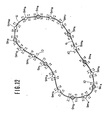
- the conveyance path 6 takes the form of a track and a plurality of stators 9A through 9J are disposed along the track at predetermined spacings.
- the plurality of stators 9A through 9J only 9B and 9G are used as stations where the carriage 1 starts and stops, while other stators act to accelerate or decelerate the carriage 1.
- carriage detectors 10 (10A-a, 10A-b, ...) for detecting the carriage 1 passing by the stators.
- Each detector 10 is constituted by a luminous element and a light receiving element disposed on the opposite sides of the conveyance path 6.
- Detectors 10 are provided on both sides of each stator so that the carriage 1 can be detected whether it is conveyed in the clockwise direction or counterclockwise direction.
- stations 9B and 9G are provided two detectors 10 on each side of these stations for detecting the running speed of the carriage when it passes through the detectors.
- the running speed of the carriage before and after the station 9G can be measured.
- the speeds of the carriage thus measured are used to calculate the value of a reverse thrust necessary to precisely stop the carriage at stations 9B and 9G.
- the principle of calculating the reverse thrust is known. More particularly, the following equation holds according to the law of preserving momentum.
- the energy of motion E of the carriage at the time of entering the second stator or station can be calculated according to the following equation.
- a clamping mechanism 11 as shown in Fig. 6 is provided for each station so as to stop the carriage also by mechanical means.
- the clamping plate 12 is normally held by a spring 13 away from the carriage 1.
- a solenoid coil 14 is energized to pull upwardly a plunger 15 for rotating a lever 16 and a shaft 17 secured thereto in a direction of an arrow. Rotation of the shaft 17 rotates the clamping plate 12 in the direction of arrow F, whereby the plate 12 is urged against the carriage 1 to stop the same.
- the drive circuit 20 is connected to a main source 21, an auxiliary source 22 and a control unit 23 for applying two to three phase alternating current from either one of the main and the auxiliary sources 21 and 22. Furthermore, the drive circuit 20 supplies the alternating current to one of the stators 9 selected by a control signal a 1 issued from the control unit 23.
- the drive circuit 20 includes such frequency converting means as an inverter for changing the frequency of the alternating current in accordance with the control signal a 1 for varying the magnitude of the thrusts generated by respective stators 9.
- the drive circuit 20 is provided with switching means for switching the input terminals of the stator coils supplied with the two or three phase alternating current for causing the stators 9 to generate a forward or reverse propelling force.
- the control unit 23 is supplied with information for generating the control signal 3i from an operating unit 24.
- the operating unit 24 is operated by a person who uses the carriage 1 and is supplied with information regarding the start and stop positions of the carriage. In this embodiment, the start and stop positions are limited to either one of the stations 9B and 9G.
- the control unit 23 controls the switching between the main and auxiliary sources 21 and 22.
- the drive circuit 20 is connected to both the main and auxiliary sources 21 and 22, but under normal state, the main source 21 is used by the control signal a 1 from the control unit 23.
- a detecting device 25 is connected to the main source 21 to detect whether the main source is in normal or abnormal state (interruption of power supply or decrease of the output caused by a fault).
- the output signal b from the detecting device 25 is supplied to the control unit 23.
- the control unit 23 detects that the main source 21 is in an abnormal state, itturns OFF the main source 21 by using a control signal a 2 while turning ON the auxiliary source 22 by the control signal a3, thus effecting the switching of the sources.
- the memory device 26 is also inputted with a start position information and a stop position information inputted from the operating unit 24 via control unit 23.
- the carriage detectors 10A-a, 10A-b, 10B-a disposed before and after respective stators are connected to the control unit 23 for receiving the detection signals from respective detectors.
- the control unit 23 calculates the speed and mass of the carriage based on the detection signals by the methods described above, thereby producing the reverse propelling force for stopping the carriage 1 in accordance with the calculated values.
- the clamping mechanisms 11 at the stations 9B and 9G are electrically connected to the control unit 23 whereby the clamping mechanisms 11 are controlled by the control unit 23.
- the operator operates the operating unit 24 for inputting informations regarding the starting position and the stopping position of the carriage 1, and then depresses a start switch, not shown. It is assumed now that the carriage 1 starts at station 9B and stops at station 9G and that the carriage 1 runs in the clockwise direction.
- the control unit 23 Upon depression of the start switch, the control unit 23 turns ON the main source 21 by the control signal a 2 .
- the control unit 23 determines timings for driving stators 9A through 9H, selection of producing the forward propelling force or the reverse propelling force and the magnitudes of these propelling forces according to a predetermined program and controls the drive circuit 20 according to the control signal a 1'
- the drive circuit 20 passes 2 or 3 phase alternating current through desired stator coils for producing magnetic flux which induces eddy current in the reaction plate 3, the product of the magnetic flux and the eddy current producing continuous forward or reverse propelling force according to Flemings lefthand law, thereby running the carriage 1 from the start station 9B and precisely stopping the carriage at station 9G.
- the system When the main source 21 becomes faulty, the system operates as follows. At the time of interruption of the power supply or when the main source 21 becomes faulty, the output of the main source 21 would decrease or turn OFF. When such abnormal condition occurs during the running of the carriage 1, the carriage cannot be runned in a system having only the main source 21. As a consequence, the stop position of the carriage is determined by its inertia at the time of occurrence of the abnormal condition and the friction resisting the inertia. Accordingly, it is not only impossible to stop the carriage at a desired position but also the carriage stops at a position intermediate of adjacent stators thus disenabling next starting.
- the source upon occurrence of an abnormal condition, is transferred to the auxiliary source 22 so as to run the carriage 1 to a terminal station (in this case stator 9G and then stop the carriage by utilizing the auxiliary source 22).
- the abnormal condition of the main source 21 is detected by the detecting device 25, the output signal b thereof being supplied to the control unit (at step 100 shown in Fig. 8).
- the control unit 23 turns OFF the main source 21 and immediately after that turns ON the auxiliary source 22 for supplying alternating current to the drive circuit 20 from the auxiliary source 22 thus effecting the transfer of the sources (see step 101). After that the carriage is runned until stop by the energy supplied from the auxiliary source 22.
- the control unit 23 After transferring the source to the auxiliary source 22, the control unit 23 detects the runned position of the carriage 1 in accordance with the signals detected by respective carriage detectors 10 (see step 102). For example, let us assume that the carriage 1 which has started from the station 9B is firstly detected by detector 101-a of stator 91 after the main source 21 become faulty.
- the memory device 26 prestores informations regarding respective stators 9 of the conveyance path 6, and arrangement of respective detectors 10 so that by recognizing these informations, the control unit 23 applies the control signal a, to the drive circuit 20 when the detector 10H-b detects the carriage for driving stator 9H (see step 103) at this time the stator 9H imparts a reverse propelling force to the carriage 1 so as to decelerate the same to some extent. More particularly, in this case, since a stator next to stator 9H in the station 9G at which the carriage is to be stopped, the control unit 23 decelerates the carriage to some extent at the stator 2H.
- the control unit 23 calculates the running speed of the carriage when it enters into the station 9G and then calculates the deceleration energy to be applied at station 9G necessary to stop the carriage in accordance with the calculated value and the mass m of the carriage already determined by the method described above. As above described, the control unit 23 applies the calculated deceleration energy to the stator 9G via the drive circuit 20 thereby stopping the carriage at the station 9G (see step 105).
- the controller 23 energizes solenoid coil 14 to urge the clamping plate 12 against the carriage 1 thereby securely holding the same at a predetermined position of the station 9G (see step 106).
- the main source 21 restores thereafter, the restoration is detected by the detecting device 25 and a detection signal b is applied to the control unit 23.
- the solenoid coil 14 of the clamping mechanism is deenergized with the result that the clamping plate 12 is retracted from the conveyance path 6 by the force of spring 13 thereby enabling the rerunning of the carriage 1.
- control unit 23 After switching to the auxiliary source 22, the control unit 23 has controlled the carriage until it reaches the desired stop position. Alternatively, it is also possible to run and stop the carriage until it reaches a start position (in this case station 9B) and restart the carriage from the start position when the fault of the source has repaired or the supply of power is resumed.
- a start position in this case station 9B
- the carriage can stop at the start position before occurrence of the abnormal thus making definite the destination of the carriage. Accordingly, when the abnormal condition is cleared, the operator can issue a running instruction to the carriage without any pause.
- the clamping mechanism 11 provided for the stations 9B and 9G of this embodiment is not always necessary. In other words, so long as the deceleration and stopping energy supplied to the drive circuit 20 of each stator is adequately controlled, the carriage can be stopped only with the braking force applied by the stator.
- the speed detecting means comprising two carriage detectors provided before and after each of the stators 9B and 9B is not always be necessary. In other words, the carriage can be stopped at a stator only with the clamping mechanism 11 provided for stators 9B and 9G respectively.
- the control unit 23 actuates the clamping mechanism 11 at a predetermined timing in accordance with the position detection of the carriage to project the clamping plate 12 on the conveyance path thereby forcibly stopping the carriage at the stator 9G or 9B.
- Figs. 9 and 10 The second embodiment of this invention will now be described with reference to Figs. 9 and 10.
- two carriage detectors 10 are installed before and after of each of the stators 9A through 91 for detecting the running speed of the carriage before and after of each stator. More particularly, in this embodiment, the carriage can stop not only at the stations 9B and 9B but also at all other stations.
- respective stators are controlled such that the carriage 1 can be stopped in a shortest time. Since it is desirable to minimize the power consumption of the auxiliary source 22 after the source has been switched to the auxiliary source 22, the position of the carriage is detected (at step 202 shown in Fig.
- step 204 After extinguishing the abnormal condition, the carriage is runned to the desired stop position by the main source 21 (see step 204).
- the clamping mechanism 11 can be provided for all stators so as to stop the carriage by the braking force exerted by the stator and the clamping force applied by the clamping mechanism at all stators 9A through 9J.
- the running speed of the carriage is low, although it is possible to stop the carriage without applying shock at stator 9 through which the carriage passes firstly, but where the speed is high it is advantageous to stepwisely decelerate the carriage with a plurality of stators.
- the position of the carriage 1 is detected by using the outputs of the carriage detectors 10 installed before and after respective stators (at step 302), and one of the stations 9B and 9G closer to the carriage is selected based on the detector output (at step 303) and the carriage is runned and stopped toward the selected station (steps 304-306).
- the carriage can run in the opposite direction. For example, where a carriage running in the clockwise direction is detected by stators 9A and 9J the carriage is runned in the opposite direction to be stopped at station 9B.
- the carriage is detected by stators 91 and 9H, the carriage is runned as it is to stop at station 9G.
- two -carriage detectors are installed before and after each of the stators 9A through 9J to enable detection of the running speed of the carriage at all stator positions so that it is easy to impart a reverse propelling force for running the carriage in the reverse direction at each stator.
- Fig. 12 shows still another embodiment of this invention in which in addition to a plurality of stations 9no-9n 6 performing normal starting and stopping, a plurality of stators 9m o -9m lo performing only acceleration and deceleration are installed between stations 9no through 9n 6 along the conveyance path 6.
- Two carriage detectors 10 are provided before and after each of the stations 9no-9n 6 and stators 9mo7--9m,o so as to measure the running speed of the carriage before and after each station and stator.
- the operator before starting the carriage, the operator operates the operating unit (see Fig. 7) to designate the starting position and the stopping position of the carriage at the plurality of stations 9no--9n6.
- the starting position and the stopping position of the carriage is stored in the memory device 26 through control unit 23. For this reason, in this embodiment too including a plurality of stations, even when the main source 21 becomes faulty, just like the first embodiment, it is possible to run and stop the carriage to the first start position and the first desired stop position by using the energy of the auxiliary source 22.
- the carriage when the main source 21 becomes faulty, the carriage can be stopped at a nearest stator, that is station.
- the main source 21 when the main source 21 becomes faulty it is switched to the auxiliary source 22 to continuously run the carriage, whereby even at the time of interruption of power supply, the carriage 1 can be run and stopped as desired.
- the conveyance path is not limited to a loop and can take many other configurations.
- the detecting device for detecting the carriage is not limited to a combination of a light projector or a luminous element and a light receiving element.
- Other suitable type detector for example an electromagnetic type detector may be used.
- Any suitable mechanism for stationary holding the carriage at the stator or station other than the illustrated clamping mechanic can be used.
- linear induction motor was used as means for imparting forward or reverse propelling force to the carriage
- other types of linear motors for example a linear step motor, and a linear direct motor can also be used.
- Any carriage or vehicle capable of continuing running after once driven by linear drive means can enjoy the benefit of this invention.
- pneumatic actuators driven by an air compressor can be used.
Landscapes
- Engineering & Computer Science (AREA)
- Power Engineering (AREA)
- Transportation (AREA)
- Mechanical Engineering (AREA)
- Control Of Vehicles With Linear Motors And Vehicles That Are Magnetically Levitated (AREA)
- Control Of Linear Motors (AREA)
Claims (11)
Applications Claiming Priority (2)
| Application Number | Priority Date | Filing Date | Title |
|---|---|---|---|
| JP85969/84 | 1984-04-26 | ||
| JP59085969A JPS60229603A (ja) | 1984-04-26 | 1984-04-26 | 搬送装置 |
Publications (3)
| Publication Number | Publication Date |
|---|---|
| EP0160523A2 EP0160523A2 (de) | 1985-11-06 |
| EP0160523A3 EP0160523A3 (en) | 1986-12-30 |
| EP0160523B1 true EP0160523B1 (de) | 1989-01-11 |
Family
ID=13873553
Family Applications (1)
| Application Number | Title | Priority Date | Filing Date |
|---|---|---|---|
| EP85302918A Expired EP0160523B1 (de) | 1984-04-26 | 1985-04-25 | Fördersystem |
Country Status (4)
| Country | Link |
|---|---|
| US (1) | US4613805A (de) |
| EP (1) | EP0160523B1 (de) |
| JP (1) | JPS60229603A (de) |
| DE (1) | DE3567434D1 (de) |
Cited By (1)
| Publication number | Priority date | Publication date | Assignee | Title |
|---|---|---|---|---|
| US10435253B2 (en) | 2013-07-19 | 2019-10-08 | Wilco Ag | Method of in-line testing devices and testing apparatus |
Families Citing this family (30)
| Publication number | Priority date | Publication date | Assignee | Title |
|---|---|---|---|---|
| JPH088723B2 (ja) * | 1985-11-02 | 1996-01-29 | 日立機電工業株式会社 | リニアモ−タを用いた搬送装置 |
| CA1282729C (en) * | 1986-01-27 | 1991-04-09 | Toshiyuki Takeuchi | Conveyor system utilizing linear motor |
| US4789815A (en) * | 1986-07-23 | 1988-12-06 | Ohi Seisakusho Co., Ltd. | Linear motor |
| JPS6364863A (ja) * | 1986-09-05 | 1988-03-23 | 株式会社東芝 | 搬送装置 |
| US4958716A (en) * | 1986-10-09 | 1990-09-25 | Kabushiki Kaisha Toshiba | Apparatus for conveying articles |
| DE3641326A1 (de) * | 1986-12-03 | 1988-06-16 | Scharf Gmbh Maschf | Foerderanlage |
| AU602059B2 (en) * | 1987-03-13 | 1990-09-27 | Utdc Inc. | A transit system |
| DE69011744T2 (de) * | 1989-06-01 | 1995-03-23 | Mazda Motor | Förderer mit Linearmotor. |
| US5105110A (en) * | 1989-11-08 | 1992-04-14 | Utdc Inc. | Linear induction motor secondary |
| US5116002A (en) * | 1990-07-05 | 1992-05-26 | Utdc, Inc. | Stopping zones in a linear motor in-track transit system |
| US5118055A (en) * | 1990-07-05 | 1992-06-02 | Utdc, Inc. | Reduced voltage braking system in a linear motor in-track transit system |
| US5127599A (en) * | 1990-07-05 | 1992-07-07 | Utdc, Inc. | Deceleration zone in a linear motor in-track transit system |
| US5157999A (en) * | 1991-07-11 | 1992-10-27 | John Borzym | Conveyor for workstations |
| GB2270215B (en) * | 1992-08-28 | 1996-06-26 | Yang Tai Her | Control circuit for an electrical DC machine |
| US5277125A (en) * | 1992-10-28 | 1994-01-11 | Bae Automated Systems, Inc. | Material handling car and track assembly having opposed magnet linear motor drive and opposed permanent magnet brake assembly |
| FR2706825B1 (fr) * | 1993-06-24 | 1995-09-01 | Teleflex Systems Sa | Dispositif de manutention a moteur lineaire comprenant des mobiles circulant le long d'un reseau |
| US5647477A (en) * | 1994-09-19 | 1997-07-15 | Kabushiki Kaisha Toshiba | Magnetic non-contact transport system |
| DE102005013349A1 (de) * | 2005-03-23 | 2006-10-05 | Bosch Rexroth Aktiengesellschaft | Linearmotor und Verfahren zum Betrieb eines Linearmotors |
| US8061214B2 (en) * | 2008-05-08 | 2011-11-22 | Lockheed Martin Corporation | Biaxial stress, sheer, permeability, and peel test method and machine to conduct the same |
| DE102010018153B4 (de) * | 2010-04-22 | 2023-11-02 | Krones Aktiengesellschaft | Transporteinrichtung und Transportverfahren für Behälterbehandlungsanlage sowie Behälterbehandlungsanlage mit solcher Transporteinrichtung |
| JP2016501800A (ja) | 2012-10-18 | 2016-01-21 | レイトラム,エル.エル.シー. | ベルトコンベヤおよび電磁駆動装置 |
| WO2016069190A1 (en) * | 2014-10-31 | 2016-05-06 | Laitram, L.L.C. | Can-spreading conveyor system and methods |
| CN109478782B (zh) * | 2016-07-21 | 2023-08-29 | 西门子医疗保健诊断公司 | 用于模块化ivd分析器容器推进器子系统的冗余功率管理 |
| JP7177785B2 (ja) | 2017-05-02 | 2022-11-24 | レイトラム,エル.エル.シー. | ブラシレス直流モータによって駆動されるトレイコンベヤ |
| EP3642142A4 (de) | 2017-06-19 | 2021-03-17 | Laitram, L.L.C. | Einschienenschalenförderer |
| US10457497B1 (en) | 2018-04-13 | 2019-10-29 | Laitram, L.L.C. | Electromagnetic conveyor system |
| US11208274B2 (en) | 2018-04-13 | 2021-12-28 | Laitram, L.L.C. | Electromagnetic conveyor system |
| US11186302B2 (en) * | 2018-11-13 | 2021-11-30 | Rockwell Automation Technologies, Inc. | Section based safety functions for independent cart applications |
| EP3763643A1 (de) * | 2019-07-08 | 2021-01-13 | Siemens Aktiengesellschaft | System und verfahren zur zustandsüberwachung beim betrieb eines fördersystems |
| JP7433556B1 (ja) * | 2023-03-23 | 2024-02-19 | 三菱電機株式会社 | リニアトラック制御装置およびリニアトラックシステム |
Family Cites Families (14)
| Publication number | Priority date | Publication date | Assignee | Title |
|---|---|---|---|---|
| GB1002588A (en) * | 1962-05-18 | 1965-08-25 | Hovercraft Dev Ltd | Improvements in and relating to traction systems |
| US3562612A (en) * | 1968-10-21 | 1971-02-09 | Westinghouse Electric Corp | Thyristor powered reversible dual motor drive with voltage and current feedback |
| FR2061525B1 (de) * | 1969-04-15 | 1973-05-25 | Linerail | |
| FR2091875B1 (de) * | 1970-03-17 | 1973-10-19 | Jeumont Schneider | |
| DE2341761C3 (de) * | 1973-08-17 | 1978-04-13 | Siemens Ag, 1000 Berlin Und 8000 Muenchen | Schaltungsanordnung zum Betrieb eines fahrweggebundenen Triebfahrzeuges mit einem synchronen Linearmotor |
| US3996858A (en) * | 1974-03-04 | 1976-12-14 | Sangl Donald W | Linear solenoid motors |
| FR2339274A1 (fr) * | 1976-01-23 | 1977-08-19 | Cem Oerlikon Traction | Procede et dispositif de recharge d'une source autonome d'energie embarquee a bord de vehicules electriques |
| JPS54139016A (en) * | 1978-04-20 | 1979-10-29 | Pioneer Electronic Corp | Linear motor drive controller |
| JPS5553427A (en) * | 1978-10-16 | 1980-04-18 | Fujitsu Ltd | Transport mechanism in vacuum |
| JPS5934541Y2 (ja) * | 1979-07-31 | 1984-09-25 | 富士通株式会社 | リニアモ−タを使用した搬送システム |
| GB2071936B (en) * | 1980-03-18 | 1984-02-15 | Bukatarevic D | Control system for an electrically driven vehicle |
| FR2502555A1 (fr) * | 1981-03-24 | 1982-10-01 | Heuliez Bus | Systeme de franchissement de carrefours pour vehicules moteurs normalement alimentes en energie electrique par une ligne de contact |
| JPS5934541A (ja) * | 1982-08-20 | 1984-02-24 | Ricoh Co Ltd | カラ−電子写真方法 |
| JPS5958853U (ja) * | 1982-10-13 | 1984-04-17 | オムロン株式会社 | デバツグ装置 |
-
1984
- 1984-04-26 JP JP59085969A patent/JPS60229603A/ja active Pending
-
1985
- 1985-04-24 US US06/726,775 patent/US4613805A/en not_active Expired - Fee Related
- 1985-04-25 DE DE8585302918T patent/DE3567434D1/de not_active Expired
- 1985-04-25 EP EP85302918A patent/EP0160523B1/de not_active Expired
Cited By (1)
| Publication number | Priority date | Publication date | Assignee | Title |
|---|---|---|---|---|
| US10435253B2 (en) | 2013-07-19 | 2019-10-08 | Wilco Ag | Method of in-line testing devices and testing apparatus |
Also Published As
| Publication number | Publication date |
|---|---|
| EP0160523A2 (de) | 1985-11-06 |
| EP0160523A3 (en) | 1986-12-30 |
| DE3567434D1 (en) | 1989-02-16 |
| JPS60229603A (ja) | 1985-11-15 |
| US4613805A (en) | 1986-09-23 |
Similar Documents
| Publication | Publication Date | Title |
|---|---|---|
| EP0160523B1 (de) | Fördersystem | |
| JPH0423508B2 (de) | ||
| KR950000123B1 (ko) | 리니어모터를 사용한 반송장치 | |
| GB1449469A (en) | Linear electric motor systems | |
| EP0246096B1 (de) | Transportsystem mit schwebendem Lastträger | |
| US4202273A (en) | Travelling object control system utilizing power control | |
| JPH0611196B2 (ja) | リニアインダクションモータ制御システム | |
| US4665349A (en) | Apparatus for controlling the running of carriage | |
| US3937431A (en) | Postioning apparatus for tracked transport vehicles with linear motor propulsion | |
| JP2624493B2 (ja) | リニア誘導モータ搬送装置 | |
| JPH0344746Y2 (de) | ||
| KR900006247B1 (ko) | 부상식(浮上式) 반송장치 | |
| US2018238A (en) | Transportation system | |
| JPH0340821Y2 (de) | ||
| JPS6181105A (ja) | 搬送装置 | |
| JP2624665B2 (ja) | リニア誘導電動機の制御装置 | |
| JP2581043B2 (ja) | リニアモ−タ式搬送装置 | |
| JPS61231804A (ja) | 走行体の加減速方式 | |
| JPS6399702A (ja) | 搬送装置 | |
| JPS62100323A (ja) | 磁気浮上式搬送装置 | |
| JPH06351286A (ja) | リニア搬送装置 | |
| JPH0344747Y2 (de) | ||
| JPS63186506A (ja) | 搬送装置の制御装置 | |
| JP2818655B2 (ja) | 走行制御装置 | |
| JPH08157061A (ja) | フリーフロー式搬送装置の加速装置 |
Legal Events
| Date | Code | Title | Description |
|---|---|---|---|
| PUAI | Public reference made under article 153(3) epc to a published international application that has entered the european phase |
Free format text: ORIGINAL CODE: 0009012 |
|
| AK | Designated contracting states |
Designated state(s): DE FR GB NL |
|
| 17P | Request for examination filed |
Effective date: 19860326 |
|
| PUAL | Search report despatched |
Free format text: ORIGINAL CODE: 0009013 |
|
| AK | Designated contracting states |
Kind code of ref document: A3 Designated state(s): DE FR GB NL |
|
| 17Q | First examination report despatched |
Effective date: 19870924 |
|
| GRAA | (expected) grant |
Free format text: ORIGINAL CODE: 0009210 |
|
| AK | Designated contracting states |
Kind code of ref document: B1 Designated state(s): DE FR GB NL |
|
| REF | Corresponds to: |
Ref document number: 3567434 Country of ref document: DE Date of ref document: 19890216 |
|
| ET | Fr: translation filed | ||
| PLBE | No opposition filed within time limit |
Free format text: ORIGINAL CODE: 0009261 |
|
| STAA | Information on the status of an ep patent application or granted ep patent |
Free format text: STATUS: NO OPPOSITION FILED WITHIN TIME LIMIT |
|
| 26N | No opposition filed | ||
| PGFP | Annual fee paid to national office [announced via postgrant information from national office to epo] |
Ref country code: FR Payment date: 19970409 Year of fee payment: 13 |
|
| PGFP | Annual fee paid to national office [announced via postgrant information from national office to epo] |
Ref country code: GB Payment date: 19970416 Year of fee payment: 13 |
|
| PGFP | Annual fee paid to national office [announced via postgrant information from national office to epo] |
Ref country code: NL Payment date: 19970428 Year of fee payment: 13 |
|
| PGFP | Annual fee paid to national office [announced via postgrant information from national office to epo] |
Ref country code: DE Payment date: 19970505 Year of fee payment: 13 |
|
| PG25 | Lapsed in a contracting state [announced via postgrant information from national office to epo] |
Ref country code: GB Free format text: LAPSE BECAUSE OF NON-PAYMENT OF DUE FEES Effective date: 19980425 |
|
| PG25 | Lapsed in a contracting state [announced via postgrant information from national office to epo] |
Ref country code: FR Free format text: THE PATENT HAS BEEN ANNULLED BY A DECISION OF A NATIONAL AUTHORITY Effective date: 19980430 |
|
| PG25 | Lapsed in a contracting state [announced via postgrant information from national office to epo] |
Ref country code: NL Free format text: LAPSE BECAUSE OF NON-PAYMENT OF DUE FEES Effective date: 19981101 |
|
| GBPC | Gb: european patent ceased through non-payment of renewal fee |
Effective date: 19980425 |
|
| NLV4 | Nl: lapsed or anulled due to non-payment of the annual fee |
Effective date: 19981101 |
|
| PG25 | Lapsed in a contracting state [announced via postgrant information from national office to epo] |
Ref country code: DE Free format text: LAPSE BECAUSE OF NON-PAYMENT OF DUE FEES Effective date: 19990202 |
|
| REG | Reference to a national code |
Ref country code: FR Ref legal event code: ST |