EP0162579A1 - Kraftwerk zur Ausnutzung von Wärmeenergie des Meeres - Google Patents
Kraftwerk zur Ausnutzung von Wärmeenergie des Meeres Download PDFInfo
- Publication number
- EP0162579A1 EP0162579A1 EP85302722A EP85302722A EP0162579A1 EP 0162579 A1 EP0162579 A1 EP 0162579A1 EP 85302722 A EP85302722 A EP 85302722A EP 85302722 A EP85302722 A EP 85302722A EP 0162579 A1 EP0162579 A1 EP 0162579A1
- Authority
- EP
- European Patent Office
- Prior art keywords
- liquid
- evaporators
- circulated
- power plant
- section
- Prior art date
- Legal status (The legal status is an assumption and is not a legal conclusion. Google has not performed a legal analysis and makes no representation as to the accuracy of the status listed.)
- Granted
Links
Images

Classifications
-
- F—MECHANICAL ENGINEERING; LIGHTING; HEATING; WEAPONS; BLASTING
- F28—HEAT EXCHANGE IN GENERAL
- F28G—CLEANING OF INTERNAL OR EXTERNAL SURFACES OF HEAT-EXCHANGE OR HEAT-TRANSFER CONDUITS, e.g. WATER TUBES OR BOILERS
- F28G13/00—Appliances or processes not covered by groups F28G1/00 - F28G11/00; Combinations of appliances or processes covered by groups F28G1/00 - F28G11/00
-
- F—MECHANICAL ENGINEERING; LIGHTING; HEATING; WEAPONS; BLASTING
- F03—MACHINES OR ENGINES FOR LIQUIDS; WIND, SPRING, OR WEIGHT MOTORS; PRODUCING MECHANICAL POWER OR A REACTIVE PROPULSIVE THRUST, NOT OTHERWISE PROVIDED FOR
- F03G—SPRING, WEIGHT, INERTIA OR LIKE MOTORS; MECHANICAL-POWER PRODUCING DEVICES OR MECHANISMS, NOT OTHERWISE PROVIDED FOR OR USING ENERGY SOURCES NOT OTHERWISE PROVIDED FOR
- F03G7/00—Mechanical-power-producing mechanisms, not otherwise provided for or using energy sources not otherwise provided for
- F03G7/04—Mechanical-power-producing mechanisms, not otherwise provided for or using energy sources not otherwise provided for using pressure differences or thermal differences occurring in nature
- F03G7/05—Ocean thermal energy conversion, i.e. OTEC
-
- Y—GENERAL TAGGING OF NEW TECHNOLOGICAL DEVELOPMENTS; GENERAL TAGGING OF CROSS-SECTIONAL TECHNOLOGIES SPANNING OVER SEVERAL SECTIONS OF THE IPC; TECHNICAL SUBJECTS COVERED BY FORMER USPC CROSS-REFERENCE ART COLLECTIONS [XRACs] AND DIGESTS
- Y02—TECHNOLOGIES OR APPLICATIONS FOR MITIGATION OR ADAPTATION AGAINST CLIMATE CHANGE
- Y02E—REDUCTION OF GREENHOUSE GAS [GHG] EMISSIONS, RELATED TO ENERGY GENERATION, TRANSMISSION OR DISTRIBUTION
- Y02E10/00—Energy generation through renewable energy sources
- Y02E10/30—Energy from the sea, e.g. using wave energy or salinity gradient
Definitions
- the present invention relates to an oceano-thermosteric power plant in which the electric power is generated by harnessing the temperature difference between warm water in the superficial layer of the ocean and cold water in the depth thereof, and, particularly, the operation efficiency on light load at night is improved and the filth deposited thereon is washed away.
- the conventional oceano-thermosteric power plant of this kind is provided with each one of an evaporator, a turbine connected with an electric generator and a condenser as for main instruments.
- the electric power generation effected by the turbine which is driven by an actuating liquid alternately evaporated and condensed on the basis of the temperature difference between the evaporator through which the warm water is circulated and the condenser through which the cold water is circulated
- the warm water circulated through the evaporator after drawn from the superficial layer of the ocean has a high temperature from 15 to 33 degrees centigrade, so that such a defect results that the filth such as planktons, eggs of fishes and shell- fishes, dusts and the like is deposited on heat- conducting surfaces of the main instruments and hence the efficiency of heat conduction is lowered.
- the conventional oceano-thermosteric power plant has a shortcoming such that the customary protection of filth can be hardly employed therefor and further results into the increase of the cost.
- An object of the present invention is to provide an oceano-thermosteric power plant in which the above shortcoming is obviated such that, at the night on light load, the operating efficiency is improved, as well as the filth deposited on the main instruments can be efficiently washed away.
- the main instruments thereof consist of the combination of plural evaporators and plural condensers, which are arranged in parallel respectively, with the turbine and the electric generator.
- the main instruments thereof consist of the combination of plural evaporators and plural condensers, which are arranged in parallel respectively, with the turbine and the electric generator.
- the numbers of the operated evaporators and the operated condensers are reduced, so as to efficiently deal with the reduced power demand.
- the power plant of the present invention is arranged in that the filth deposited on the main instruments at the daytime can be washed away with the back-flowing clean cold water by means of circulating the excessive cold water saved in the unoperated condensers through the unoperated evaporators in the direction opposite to the ordinary circulation of the warm water under the periodical alternation of the unoperated evaporators, so as to maintain the high efficiency of heat conduction effected by all of the evaporators under the continuation of the electric power generation.
- the cavitation caused by the re-evaporation of the actuating liquid can be prevented by means of enclosing the circulating path thereof from each of outlets of the evaporators to the supplying pump therefor with water jackets.
- the present invention is featured in that, in the oceano-thermosteric power plant arranged such that the electric power generation is effected by the vapor of the actuating liquid, which vapor is formed by the evaporation thereof effected by the warm water supplied to the evaporating section after drawn from the superficial layer of the ocean and introduced into the electric power generating section, the actuating liquid, which is formed by condensing the vapor thereof exhausted from the electric power generating section with the cold water circulated through the condensing section after drawn from the depth of the ocean, being circulated through the evaporating section via a liquid reservoir and a supplying pump, the evaporating section and the condensing section are provided with plural evaporators and plural condensers respectively, a part of the plural evaporators being alternately situated at the night without the introduced warm water, so as to be unoperated, meanwhile the cold water being circulated alternately through the part of the plural evaporators in the direction opposite to the warm water circulated at the operation
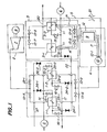
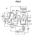
- A is an oceano-thermosteric power plant; 1 is an evaporating section; 1-1 and 1-2 are evaporators; 2 is an electric power generating section; 3 is a condensing section; 3-1 and 3-2 are condensers; 4 is a liquid supplying section; 9 is a liquid reservoir; 10 is a liquid supplying pump; 11 is an actuating liquid inlet; 12 is a water jacket; 13-1 to 13-8 are stopping valves; 14 is a warm water pipe; 15-1 and 15-2 are inlet valves; 16-1 and 16-2 are outlet valves; 17 is a warm water exhausting pipe; 18 is a cold water pipe; 19-1 and 19-2 are cold water valves; 20 is a warm water exhausting pipe; 21 is a throttle valve; 22 is an elongated portion; 23-1 and 23-2 are warm water inlets; 24-1 and 24-2 are washing water inlet valves; 25-1 and 25-2 are warm water inlets; 26-1 and 26-2 are washing water outlet valves; and
- the oceano-thermosteric power plant arranged as shown in Fig. 1 consists of an evaporating section 1, an electric power generating section 2, a condensing section 3, a liquid supplying section 4, a warm water pump 5 and a cold water pump 6, these sections and instruments being connected with each other through pipes and valves.
- the evaporating section 1 is arranged such that two evaporators 1-1 and 1-2 are connected through with each other in parallel with respect to the actuating liquid, meanwhile together connected with a warm water pump 5 in common, so as to evaporate the actuating liquid by heating it with the warm water supplied from the warm water pump 5.
- the electric power generating section 2 consists of a turbine 7 driven by the vapor of the actuating liquid and an electric generator 8 connected therewith.
- the condensing section 3 is arranged such that two condensers of the first 3-1 and the second 3-2 are connected with each other in parallel, so as to condense the vapor of the actuating liquid which vapor is exhausted from the turbine 7 by means of circulating the cold water drawn from the depth of the ocean by a cold water pump 6 therethrough.
- the liquid supplying section 4 consists of a liquid reservoir 9 and a liquid supplying pump 10, so as to pressure-transport the actuating liquid separated from the vapor thereof through the liquid reservoir 9 into the evaporating section 1 through the liquid supplying pump 10.
- a suction head required for obviating the vapor locking caused by the cavitation is provided between the liquid reservoir 9 and the liquid supplying pump 10.
- the liquid path from an actuating liquid outlet 11 of the condensing section 3 to an inhaling inlet 10-1 is enclosed with a water jacket 12 over all of the surrounding surface thereof including the liquid reservoir 9, so as to further cool the previously condensed actuating liquid for obviating the occurrence of the perturbation caused by the back pressure of the turbine 7 by means of preventing the generation of bubbles in the actuating liquid.
- it can be attained together therewith to lower the institution height of the power plant A by means of lowering the suction head of the liquid supplying pump 10 through this cooling of the actuating liquid.
- the actuating liquid is vaporized by the pressure transportation from the liquid reservoir 9 to the first and the second evaporators 1-1 and 1-2 provided in the evaporating section 1 through the liquid supplying pump 10, the vapor of the actuating liquid being supplied into the turbine 7, so as to effect the electric power generation through the electric generator 8 driven by the turbine 7. Thereafter, the vapor of the actuating liquid which vapor is exhausted from the turbine 7 is condensed by the passage through the first and the second condensers 3-1 and 3-2 in the condensing section 3, so as to return into the actuating liquid to be brought back into the liquid reservoir 9 through the above mentioned cycle.
- the heat energy obtained on the basis of the temperature difference between the warm water in the evaporating section 1 and the cold water in the condensing section 3 is converted into the electric energy having the amount corresponding to the state variation of the actuating liquid, so as to derive the required electric power therefrom.
- the numerals 13-1 to 13-8 denote stopping valves attached with back sheets which valves are provided for stopping the circulation of the actuating liquid through the unoperated evaporators and the unoperated condensers.
- the warm water drawn from the superficial layer of the ocean through the warm water pump 5 is branched through warm water pipes 14 and supplied to the first and the second evaporations 1-1 and 1-2 through a first and a second inlet valves 15-1 and 15-2 respectively, so as to heat the actuating liquid therein. Thereafter, the warm water is exhausted through a warm water exhausting pipe 17 after jointed through a first and a second outlet valves 16-1 and 16-2 respectively.
- the cold water drawn from the depth of the ocean through the cold water pump 6 is branched through cold water pipes 18 and supplied to the first and the second condensers 3-1 and 3-2 through a first and a second cold water valves 19-1 and 19-2 respectively, so as to cool the actuating liquid. Thereafter, the cold water is jointed and exhausted through a cold water exhausting pipe 20.
- the circulating path m from each of actuating liquid outlets 11 of the condensers 3-1, 3-2 to the stopping valves 13-4, 13-8, the circulating path n from those stopping valves 13-4, 13-8 to the liquid reservoir 9 and the circulating path p from the liquid reservoir 9 to the liquid supplying pump 10 including the stopping valves 13-4, 13-8 and the liquid reservoir 9 are enclosed by the water jackets 12 surrounding outer surfaces thereof, those water jackets 12 being supplied with the cold water introduced through a cold water bypass s connected with the cold water pipe 18, so as to cool those articles of the circulating paths m, n, p, the liquid reservoir 9 and the stopping valves 13-4, 13-8 from the outer surfaces thereof.
- 21 denotes a throttle valve provided in the midway of the cold water bypass s, so as to regulate the amount of the cold water flowing through the water jackets 12.
- an elongated portion 22 is branched from the cold water pipe 18 toward the evaporating section 1, and the tip of this elongated portion 22 being further branched and connected with the half ways between respective warm water outlets 23-1 and 23-2 of the first and the second evaporators and the first and the second outlet valves 16-1 and 16-2 respectively through a first and a second washing water inlet valves 24-1 and 24-2.
- washing water supplied as mentioned above is exhausted through a washing water exhausting pipe 27 after jointed through a first and a second washing water outlet valves 26-1 and 26-2 which are branched and connected respectively with the halfways between a first and a second warm water inlets 25-1 and 25-2 of the first and the second evaporator 1-1 and 1-2 and the inlet valves 15-1 and 15-2.
- both of the warm and the cold waters and the actuating liquid are circulated in parallel through the first and the second evaporators 1-1, 1-2 in the evaporating section 1 and the first and the second condensers 3-1, 3-2 therein, so as to deal with the electric power demand increased at the daytime by means of carrying out the full power operation maximizing both of amounts of evaporated and condensed actuating liquids.
- the excessive cold water drawn by the cold water pump 6 is circulated through the second washing water inlet valve 24-2 from the second warm outlet 23-2 toward the second warm water inlet 25-2, in other words, in the direction opposite to the ordinarily circulated warm water, so as to wash away the filth deposited inside the second evaporator 1-3 at the daytime with the back flow of cold water through the second washing water outlet valve 26-2 as well as to exhaust it outside the power plant A through a washing water exhausting pipe 27.
- the efficiency of heat exchange at the whole power plant A can be further improved by the sequential alternation at every predetermined period of the pair'of evaporator and condenser to be unoperated and to be washed.
- the cavitation caused by the re-evaporation of the actuating liquid can be prevented by means of enclosing the actuating liquid path from the first and the second condensers 3-1 and 3-2 to the liquid supplying pump 10 with the water jackets 12 through which the cold water is circulated, and hence the occurrence of perturbation caused by the back pressure of the turbine can be prevented also.
- the quiet and smooth revolution thereof can be attained, as well as the suction head required for the liquid supplying pump 10 can be lowered, so as to lower the institution height of the power plant A.
- the highest peak in the summer of the electric power demand can be dealt with by constituting the evaporating and the condensing sections of plural evaporators and condensers respectively, meanwhile the seasonally lowered peak in the winter of the electric power demand can be dealt with by unoperating a part of those plural evaporators and condensers for a long time, during which the decomposition maintenance of those unoperated instruments and the removal of the filth deposited thereon are carried out.
- the evaporating and the condensing sections are provided with plural evaporators and plural condensers respectively, respective parts of which are alternately unoperated, when the electric power demand is reduced.
- the excessive cold water drawn from the depth of the ocean and saved by the unoperated condensers is circulated through the unoperated evaporators in the direction opposite to the warm water drawn from the superficial layer of the ocean and supplied into those evaporators on the ordinary operation.
- the filth deposited inside the operated evaporators can be washed away, as well as the efficiency of heat exchange effected by those operated evaporators can be maintained at high level by the alternate unoperation of those condensers and evaporators.
- the circulating path of the actuating liquid in the power plant according to the present invention is enclosed by the water jacket from the outlets of the condensers to the liquid supplying pump, so as to obviate the cavitation of the actuating liquid. Consequently, the evident effects as mentioned above can be obtained according to the present invention.
Landscapes
- Engineering & Computer Science (AREA)
- Chemical & Material Sciences (AREA)
- Combustion & Propulsion (AREA)
- Mechanical Engineering (AREA)
- General Engineering & Computer Science (AREA)
- Life Sciences & Earth Sciences (AREA)
- Biodiversity & Conservation Biology (AREA)
- General Life Sciences & Earth Sciences (AREA)
- Oceanography (AREA)
- Sustainable Development (AREA)
- Basic Packing Technique (AREA)
- Engine Equipment That Uses Special Cycles (AREA)
Applications Claiming Priority (2)
| Application Number | Priority Date | Filing Date | Title |
|---|---|---|---|
| JP7588/84 | 1984-04-17 | ||
| JP59075888A JPS60228201A (ja) | 1984-04-17 | 1984-04-17 | 塊粒食品の高速自動缶詰装置 |
Publications (2)
| Publication Number | Publication Date |
|---|---|
| EP0162579A1 true EP0162579A1 (de) | 1985-11-27 |
| EP0162579B1 EP0162579B1 (de) | 1990-01-31 |
Family
ID=13589286
Family Applications (1)
| Application Number | Title | Priority Date | Filing Date |
|---|---|---|---|
| EP85302722A Expired - Lifetime EP0162579B1 (de) | 1984-04-17 | 1985-04-17 | Kraftwerk zur Ausnutzung von Wärmeenergie des Meeres |
Country Status (2)
| Country | Link |
|---|---|
| EP (1) | EP0162579B1 (de) |
| JP (1) | JPS60228201A (de) |
Cited By (2)
| Publication number | Priority date | Publication date | Assignee | Title |
|---|---|---|---|---|
| EP0649985A1 (de) * | 1993-09-22 | 1995-04-26 | Saga University | Thermischer Kraftgenerator |
| US10138007B2 (en) | 2013-06-21 | 2018-11-27 | Gima, S.P.A. | Unit and method for filling containing elements of single-use capsules for extraction or infusion beverages |
Families Citing this family (8)
| Publication number | Priority date | Publication date | Assignee | Title |
|---|---|---|---|---|
| JPS63117821A (ja) * | 1986-11-07 | 1988-05-21 | Tsumura & Co | 粉粒体の計量充填装置 |
| DE4017684A1 (de) * | 1990-06-01 | 1991-12-05 | Umwelt & Energietech | Verfahren zur nutzung von energiepotentialen, insbesondere mit kleinen temperaturdifferenzen |
| JPH04308331A (ja) * | 1991-04-05 | 1992-10-30 | Nippon Carbureter Co Ltd | 燃料噴射弁を具えたエンジンの吸気管装置 |
| JPH0534101U (ja) * | 1991-09-30 | 1993-05-07 | 日出次 辻田 | 摺り切り棒 |
| JP3623819B2 (ja) * | 1995-04-28 | 2005-02-23 | 北海製罐株式会社 | 食品の詰め込み装置 |
| RU2116465C1 (ru) * | 1996-08-21 | 1998-07-27 | Станислав Андреевич Понятовский | Энергетическая установка |
| JP5550176B2 (ja) * | 2010-03-29 | 2014-07-16 | 鈴茂器工株式会社 | 計量装置およびこの計量装置を用いた被計量物の個装装置 |
| JP2018095268A (ja) * | 2016-12-09 | 2018-06-21 | シブヤパッケージングシステム株式会社 | 充填装置 |
Citations (4)
| Publication number | Priority date | Publication date | Assignee | Title |
|---|---|---|---|---|
| US1493368A (en) * | 1920-03-12 | 1924-05-06 | Merz Franco | Production of motive force |
| GB1059050A (en) * | 1964-08-31 | 1967-02-15 | James Hilbert Anderson | Method and apparatus for obtaining power from a naturally occurring body of water |
| US3975912A (en) * | 1974-11-25 | 1976-08-24 | Clarence Kirk Greene | Geothermal dual energy transfer method and apparatus |
| US4062189A (en) * | 1976-09-29 | 1977-12-13 | Pacific Power And Protein, Inc. | Method of preventing the accumulation of micro-organisms in thermal energy conversion systems |
Family Cites Families (3)
| Publication number | Priority date | Publication date | Assignee | Title |
|---|---|---|---|---|
| JPS5260795A (en) * | 1975-11-13 | 1977-05-19 | Shionogi Seiyaku Kk | Powder charger |
| DE2928521A1 (de) * | 1979-07-14 | 1981-01-15 | Adolf Rambold | Becher-dosierverfahren und abfuellmaschine zum durchfuehren des verfahrens |
| JPS58171801U (ja) * | 1982-05-11 | 1983-11-16 | 株式会社石田衡器製作所 | 物品供給装置 |
-
1984
- 1984-04-17 JP JP59075888A patent/JPS60228201A/ja active Granted
-
1985
- 1985-04-17 EP EP85302722A patent/EP0162579B1/de not_active Expired - Lifetime
Patent Citations (4)
| Publication number | Priority date | Publication date | Assignee | Title |
|---|---|---|---|---|
| US1493368A (en) * | 1920-03-12 | 1924-05-06 | Merz Franco | Production of motive force |
| GB1059050A (en) * | 1964-08-31 | 1967-02-15 | James Hilbert Anderson | Method and apparatus for obtaining power from a naturally occurring body of water |
| US3975912A (en) * | 1974-11-25 | 1976-08-24 | Clarence Kirk Greene | Geothermal dual energy transfer method and apparatus |
| US4062189A (en) * | 1976-09-29 | 1977-12-13 | Pacific Power And Protein, Inc. | Method of preventing the accumulation of micro-organisms in thermal energy conversion systems |
Non-Patent Citations (1)
| Title |
|---|
| JOURNAL OF ENGINEERING FOR INDUSTRY, vol. 96, no. 4, November 1974, pages 1119-1129, New York, US; J.G. McGOWAN et al.: "Ocean thermal difference power-plant design" * |
Cited By (3)
| Publication number | Priority date | Publication date | Assignee | Title |
|---|---|---|---|---|
| EP0649985A1 (de) * | 1993-09-22 | 1995-04-26 | Saga University | Thermischer Kraftgenerator |
| US5588297A (en) * | 1993-09-22 | 1996-12-31 | Saga University | Thermal power generator |
| US10138007B2 (en) | 2013-06-21 | 2018-11-27 | Gima, S.P.A. | Unit and method for filling containing elements of single-use capsules for extraction or infusion beverages |
Also Published As
| Publication number | Publication date |
|---|---|
| JPH0440245B2 (de) | 1992-07-02 |
| EP0162579B1 (de) | 1990-01-31 |
| JPS60228201A (ja) | 1985-11-13 |
Similar Documents
| Publication | Publication Date | Title |
|---|---|---|
| US4628212A (en) | Oceano-thermosteric power plant | |
| AU759283B2 (en) | Desalination method and desalination apparatus | |
| US7225620B2 (en) | Diffusion driven water purification apparatus and process | |
| US6919000B2 (en) | Diffusion driven desalination apparatus and process | |
| CN1108993C (zh) | 利用太阳能淡化或净化海水或微咸水的设备 | |
| JP5462939B2 (ja) | 発電・海水淡水化複合プラント | |
| US9739504B2 (en) | Steam generator and energy supply system using the same | |
| EP0649985B1 (de) | Thermischer Kraftgenerator | |
| EP0162579A1 (de) | Kraftwerk zur Ausnutzung von Wärmeenergie des Meeres | |
| JP2009081970A (ja) | 熱電発電装置及び該熱電発電装置を用いた発電システム | |
| GB2369783A (en) | Desalination process | |
| JP3964069B2 (ja) | 淡水化装置 | |
| WO1997034831A1 (en) | Saltwater distillation housing | |
| EP0114830B1 (de) | Entsalzer für brackiges oder salzhaltiges wasser | |
| US9285174B2 (en) | Thermal energy system and method for its operation | |
| JP4139597B2 (ja) | 淡水化装置 | |
| US4372126A (en) | Closed cycle system for generating usable energy from waste heat sources | |
| US20150000275A1 (en) | Multi-stage otec power plant | |
| US2707239A (en) | Apparatus for utilizing waste heat | |
| WO2004060812A1 (en) | Diffusion driven desalination apparatus and process | |
| KR200154391Y1 (ko) | 발전소 폐열을 이용한 담수 생성장치 | |
| CN211198925U (zh) | 一种交替海水淡化装置 | |
| AU707461B2 (en) | Recooling system | |
| RU2768909C2 (ru) | Автономный самоориентирующийся солнечный опреснитель-электрогенератор | |
| JPS58112082A (ja) | 蒸発法 |
Legal Events
| Date | Code | Title | Description |
|---|---|---|---|
| PUAI | Public reference made under article 153(3) epc to a published international application that has entered the european phase |
Free format text: ORIGINAL CODE: 0009012 |
|
| AK | Designated contracting states |
Designated state(s): DE FR GB SE |
|
| 17P | Request for examination filed |
Effective date: 19860512 |
|
| 17Q | First examination report despatched |
Effective date: 19870525 |
|
| GRAA | (expected) grant |
Free format text: ORIGINAL CODE: 0009210 |
|
| AK | Designated contracting states |
Kind code of ref document: B1 Designated state(s): DE FR GB SE |
|
| REF | Corresponds to: |
Ref document number: 3575769 Country of ref document: DE Date of ref document: 19900308 |
|
| ET | Fr: translation filed | ||
| PLBE | No opposition filed within time limit |
Free format text: ORIGINAL CODE: 0009261 |
|
| STAA | Information on the status of an ep patent application or granted ep patent |
Free format text: STATUS: NO OPPOSITION FILED WITHIN TIME LIMIT |
|
| 26N | No opposition filed | ||
| EAL | Se: european patent in force in sweden |
Ref document number: 85302722.5 |
|
| REG | Reference to a national code |
Ref country code: GB Ref legal event code: IF02 |
|
| PGFP | Annual fee paid to national office [announced via postgrant information from national office to epo] |
Ref country code: SE Payment date: 20040406 Year of fee payment: 20 |
|
| PGFP | Annual fee paid to national office [announced via postgrant information from national office to epo] |
Ref country code: FR Payment date: 20040408 Year of fee payment: 20 |
|
| PGFP | Annual fee paid to national office [announced via postgrant information from national office to epo] |
Ref country code: GB Payment date: 20040414 Year of fee payment: 20 |
|
| PGFP | Annual fee paid to national office [announced via postgrant information from national office to epo] |
Ref country code: DE Payment date: 20040429 Year of fee payment: 20 |
|
| PG25 | Lapsed in a contracting state [announced via postgrant information from national office to epo] |
Ref country code: GB Free format text: LAPSE BECAUSE OF EXPIRATION OF PROTECTION Effective date: 20050416 |
|
| REG | Reference to a national code |
Ref country code: GB Ref legal event code: PE20 |
|
| EUG | Se: european patent has lapsed |