EP0163185A2 - Scie sauteuse - Google Patents
Scie sauteuse Download PDFInfo
- Publication number
- EP0163185A2 EP0163185A2 EP85105810A EP85105810A EP0163185A2 EP 0163185 A2 EP0163185 A2 EP 0163185A2 EP 85105810 A EP85105810 A EP 85105810A EP 85105810 A EP85105810 A EP 85105810A EP 0163185 A2 EP0163185 A2 EP 0163185A2
- Authority
- EP
- European Patent Office
- Prior art keywords
- saw blade
- saw
- saw table
- attachment
- stabilizing elements
- Prior art date
- Legal status (The legal status is an assumption and is not a legal conclusion. Google has not performed a legal analysis and makes no representation as to the accuracy of the status listed.)
- Granted
Links
Images


Classifications
-
- B—PERFORMING OPERATIONS; TRANSPORTING
- B23—MACHINE TOOLS; METAL-WORKING NOT OTHERWISE PROVIDED FOR
- B23Q—DETAILS, COMPONENTS, OR ACCESSORIES FOR MACHINE TOOLS, e.g. ARRANGEMENTS FOR COPYING OR CONTROLLING; MACHINE TOOLS IN GENERAL CHARACTERISED BY THE CONSTRUCTION OF PARTICULAR DETAILS OR COMPONENTS; COMBINATIONS OR ASSOCIATIONS OF METAL-WORKING MACHINES, NOT DIRECTED TO A PARTICULAR RESULT
- B23Q11/00—Accessories fitted to machine tools for keeping tools or parts of the machine in good working condition or for cooling work; Safety devices specially combined with or arranged in, or specially adapted for use in connection with, machine tools
- B23Q11/0042—Devices for removing chips
- B23Q11/0046—Devices for removing chips by sucking
-
- B—PERFORMING OPERATIONS; TRANSPORTING
- B23—MACHINE TOOLS; METAL-WORKING NOT OTHERWISE PROVIDED FOR
- B23D—PLANING; SLOTTING; SHEARING; BROACHING; SAWING; FILING; SCRAPING; LIKE OPERATIONS FOR WORKING METAL BY REMOVING MATERIAL, NOT OTHERWISE PROVIDED FOR
- B23D49/00—Machines or devices for sawing with straight reciprocating saw blades, e.g. hacksaws
- B23D49/10—Hand-held or hand-operated sawing devices with straight saw blades
- B23D49/16—Hand-held or hand-operated sawing devices with straight saw blades actuated by electric or magnetic power or prime movers
- B23D49/162—Pad sawing devices
-
- B—PERFORMING OPERATIONS; TRANSPORTING
- B23—MACHINE TOOLS; METAL-WORKING NOT OTHERWISE PROVIDED FOR
- B23D—PLANING; SLOTTING; SHEARING; BROACHING; SAWING; FILING; SCRAPING; LIKE OPERATIONS FOR WORKING METAL BY REMOVING MATERIAL, NOT OTHERWISE PROVIDED FOR
- B23D51/00—Sawing machines or sawing devices working with straight blades, characterised only by constructional features of particular parts; Carrying or attaching means for tools, covered by this subclass, which are connected to a carrier at both ends
- B23D51/02—Sawing machines or sawing devices working with straight blades, characterised only by constructional features of particular parts; Carrying or attaching means for tools, covered by this subclass, which are connected to a carrier at both ends of beds; of guiding arrangements for work-tables or saw carriers; of frames
- B23D51/025—Sawing machines or sawing devices working with straight blades, characterised only by constructional features of particular parts; Carrying or attaching means for tools, covered by this subclass, which are connected to a carrier at both ends of beds; of guiding arrangements for work-tables or saw carriers; of frames of arrangements for guiding the saw blade
- B23D51/026—Sawing machines or sawing devices working with straight blades, characterised only by constructional features of particular parts; Carrying or attaching means for tools, covered by this subclass, which are connected to a carrier at both ends of beds; of guiding arrangements for work-tables or saw carriers; of frames of arrangements for guiding the saw blade by plural opposed guide surfaces
-
- B—PERFORMING OPERATIONS; TRANSPORTING
- B23—MACHINE TOOLS; METAL-WORKING NOT OTHERWISE PROVIDED FOR
- B23D—PLANING; SLOTTING; SHEARING; BROACHING; SAWING; FILING; SCRAPING; LIKE OPERATIONS FOR WORKING METAL BY REMOVING MATERIAL, NOT OTHERWISE PROVIDED FOR
- B23D59/00—Accessories specially designed for sawing machines or sawing devices
- B23D59/001—Measuring or control devices, e.g. for automatic control of work feed pressure on band saw blade
- B23D59/002—Measuring or control devices, e.g. for automatic control of work feed pressure on band saw blade for the position of the saw blade
-
- B—PERFORMING OPERATIONS; TRANSPORTING
- B23—MACHINE TOOLS; METAL-WORKING NOT OTHERWISE PROVIDED FOR
- B23D—PLANING; SLOTTING; SHEARING; BROACHING; SAWING; FILING; SCRAPING; LIKE OPERATIONS FOR WORKING METAL BY REMOVING MATERIAL, NOT OTHERWISE PROVIDED FOR
- B23D59/00—Accessories specially designed for sawing machines or sawing devices
- B23D59/006—Accessories specially designed for sawing machines or sawing devices for removing or collecting chips
-
- B—PERFORMING OPERATIONS; TRANSPORTING
- B27—WORKING OR PRESERVING WOOD OR SIMILAR MATERIAL; NAILING OR STAPLING MACHINES IN GENERAL
- B27G—ACCESSORY MACHINES OR APPARATUS FOR WORKING WOOD OR SIMILAR MATERIALS; TOOLS FOR WORKING WOOD OR SIMILAR MATERIALS; SAFETY DEVICES FOR WOOD WORKING MACHINES OR TOOLS
- B27G19/00—Safety guards or devices specially adapted for wood saws; Auxiliary devices facilitating proper operation of wood saws
- B27G19/10—Measures preventing splintering of sawn portions of wood
Definitions
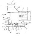
- the invention relates to a jigsaw with a Mocorkopf and with a saw table, which has a hollow profile-shaped attachment, which contains a central, longitudinally extending channel for dust extraction, which opens just behind the back of a saw blade at the top of the saw table and one Has suction nozzle to which a suction line can be connected.
- Motorized jigsaws are widely used for commercial and home improvement applications. They have a saw table that carries a motor head with a drive unit. The latter drives a saw blade holder in a reciprocating stroke movement. A saw blade can be clamped on the saw blade holder, which reaches through the saw table. In operation, the jigsaw is usually held on the motor head and guided over the workpiece to be sawed, the saw table being supported on the workpiece and the protruding end of the saw blade working against the workpiece.
- the object of the invention is to improve and design the jigsaw of the type mentioned at the outset with regard to the suction device in such a way that stable guidance of the pivoted motor head is ensured with this improved suction power.
- the attachment is formed in one piece with the saw table and with the suction nozzle and has an upwardly curved, contoured as a jacket section of a circular cylinder, which acts as a guide surface for a pivotable the attached motor head is used.
- the solution according to the invention thus proposes to use the semi-cylindrical attachment containing the dust extraction duct as a carrier for the motor head pivotally mounted thereon and thus to lend it a double function as a stable swivel mount for the motor head and housing wall of the dust extraction duct, so that special housing parts for the suction device are omitted and because of the central arrangement of the dust extraction duct on the saw table, the flow path is extremely short and no dead volumes occur.
- This and the fact that the attachment is in one piece with the saw table and with the suction nozzle leads to a highly effective dust extraction.
- the entire arrangement is in terms of construction and forth positionally particularly easy.
- the suction nozzle characterized in claim 2 produces a fluidically particularly favorable transition between the semi-cylindrical inner cross section of the attachment and an elastic hose of a conventional farm.
- the passage cross section is maintained over the full length of the suction channel.
- a slide is provided according to the invention, by means of which the entry of false air into the suction channel is prevented and the suction effect is improved.
- the slider is captively inserted between the footplate and the running shoe releasably fastened thereon and guided on the footplate and / or the running shoe.
- a motorized hand jigsaw is shown. It has a saw table 1, which carries a motor head (drive motor and plants) 2 with a drive unit (rod motor) 3.
- the drive unit 3 drives a saw blade holder 4 in a periodic up and down movement.
- a downwardly projecting saw blade 5 can be clamped, which extends through a recess in the saw table 1 and projects beyond the outsole 6 of the saw table 1.
- the jigsaw is usually placed on a workpiece to be sawed with the saw table 1.
- the saw table 1 is constructed in two parts. It consists of a foot plate 10 and a detachably connected running shoe 11, which covers the underside of the foot plate 10 and projects beyond the edge of the foot plate 10 on all sides.
- the base plate 10 is made of metal, and in particular light metal such as e.g. Die-cast aluminum.
- the running shoe 11, however, is made of plastic. It has the shape of a flat plate with a circumferential, upwardly projecting edge web 12. The footplate 10 is inserted into the running shoe 11 and is positively enclosed by the edge web 12.
- the detachable connection between the base plate 10 and the running shoe 11 can be made, for example, by screwing.
- the metallic base plate 10 gives the saw table 1 the required rigidity, which can be increased by an arrangement of suitable reinforcing ribs or by the choice of the plate thickness and can be designed according to the requirements.
- the reinforcing ribs can be varied in many ways by the uncomplicated aluminum die-casting technology.
- the running shoe 11 made of plastic, and in particular a thermoplastic material, brings about a low-friction sliding of the jigsaw on the workpiece to be sawn. Sensitive workpiece surfaces are not scratched or damaged by knocking from the side, since the running shoe 11 projects beyond the base plate 10 on all sides.
- the running shoe 11 made of plastic effects a certain vibration and shock absorption.
- the elastic properties of the saw table 1 can be further improved by inserting an elastic intermediate layer, for example made of rubber (not shown) between the foot plate 10 and the running shoe 11.
- This intermediate layer can be fastened by clamping and thereby have a sealing effect, which is desirable for reasons which will be explained in more detail below.
- the saw table 1 has an elongated rectangular plan, wherein in the area of the saw blade 5 there is a central recess 14 which is open towards the narrow side 13.
- the saw table is divided here in a U-shape, the recess 14 being flanked on both sides by tabs 15. It is understood that both the foot plate 10 and the running shoe 11 have such a U-recess. Threaded bores for screwing the running shoe 11 to the footplate 10 are shown at 16.
- a hollow profile-shaped attachment 17 is ver bound.
- the attachment 17 can be integrally formed on the base plate 10, in particular using casting technology. It is arranged centrally on the top of the saw table 1, in the longitudinal direction of which it extends.
- the attachment 17 extends from the rear narrow side 18 of the saw table 1 to just in front of the recess 14 in which the saw blade 5 runs. Its front edge is shown at 19.
- the attachment 17 is curved upwards.
- Its upper side 20 is contoured as a jacket section of a circular cylinder, the angular extent in the exemplary embodiment shown being approximately 180 °; the attachment 17. thus has approximately the shape of a halved circular cylinder.
- the attachment 17 carries the motor head 2, which is pivotally mounted on the cylinder surface 20.
- the motor head 2 is convexly curved on its underside 21 to complement the attachment 17. Its support thus also forms the section of a cylindrical surface, the angular extent of which is, however, considerably smaller than that of the attachment 17, so that there is play for a pivoting movement.
- the motor head 2 comes into positive contact with the attachment 17, and it is locked in the desired angular positions on the attachment 17 by means of a clamping screw 22.
- the arrangement of the clamping screw 22 results from the gating in FIG. 1.
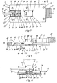
- the clamping screw 22 extends from below through an elongated hole 62 (see FIG. 6) in the attachment 17, which extends in the circumferential direction of the cylinder jacket surface 20.
- the head of the clamping screw 22 comes to lie inside the attachment 17 and its shaft is screwed into the base of the motor head 2.
- the head of the clamping screw 22 works directly or with the interposition of a suitable clamping jaw 23 against the inner surface of the attachment 17.
- the motor head 2 is thus tensioned against the attachment 17.
- the saw blade 5 is oriented perpendicular to the saw table plane.
- the clamping screw 22 is at the zenith of the attachment 17, and a straight saw cut is achieved.
- the motor head 2 with the saw blade holder 4 and saw blade 5 is pivoted on the attachment 17.
- the clamping screw 22 is loosened by reaching through an opening 25 in the saw table 1, which is described in more detail, with a screwing tool.
- the angle of inclination can be read off a scale 24.
- the motor head 2 can be pivoted on both sides by 45 ° each.
- the attachment 1-7 serving to pivot the motor head 2 also serves to extract dust from the interface of the saw blade 5.
- the interior of the attachment 17 forms a suction channel for this purpose, which opens close behind the back of the saw blade 5 at the top of the saw table 1.
- a suction nozzle 27 At the opposite end of the attachment 17 there is a suction nozzle 27 to which a suction line can be connected, for example in the form of an elastic hose.
- the suction nozzle 27 forms an axial extension of the attachment 17.
- the suction nozzle 27 is offset from the top 17. It stands beyond the rear narrow side 18 of the saw table 1 and is provided with suitable holding ribs for fastening a hose.
- the clear opening of the suction nozzle should have a width that is at least that of the suction channel 26 in Inside of the attachment 17 corresponds. It is therefore advisable to give the suction nozzle 27 an elliptical or oval cross section, its width being greater than its height (cf. FIGS. 1 and 4).
- the base plate 10 is open towards the bottom in the area of the suction channel 26.
- the suction channel 26 is covered by the running shoe 11, which is screwed to the footplate 10 with mounting screws 28 (cf. FIG. 5).
- the running shoe 11 can be removed in a simple manner in order to clean the suction channel 26, which may occasionally be necessary.
- the two-part construction of the saw table 1 also offers the possibility of changing the running shoe 11 made of plastic in the event of wear.
- Base plate 10 and running shoe 11 are in flat contact, which normally ensures adequate sealing of the suction channel 26.
- an elastic intermediate layer can optionally also be introduced between the base plate 10 and the running shoe 11, which at the same time improves the sealing of the suction channel 26 and the elastic properties of the saw table 1.
- the elongated hole 62 through which the shaft of the clamping screw 22 protrudes is from the clamping jaws 22 and / or the base of the motor head 2 covered, so that no false air enters the suction channel 26.
- the opening 25 through which the clamping screw 22 from the lower side of the saw table 1 is accessible, is closed according to the invention with a slide 29.
- the slide 29 is shown in FIG. 4 in its open position and in FIG. 5 in its closed position.
- the slider 29 consists of a flat plate 30, from which an operating button 31 protrudes downward.
- the slide plate 30 is movably guided on the foot plate 10 in the longitudinal direction.
- Grooves 32 are used for this purpose, which are recessed on both sides at the edge of the suction channel 26 and form a step-like extension of the suction channel 26.
- the slide plate 30 is inserted into these grooves 32, whereby it comes to lie sunk under the surface of the foot plate 10.
- the extent of the grooves 32 in the longitudinal direction of the saw table 1 is greater than the length of the slide plate 3D, so that the latter can be moved in the grooves 32.
- the slide 29 is located as a loose insert between the running shoe 11 and / footplate 10, it being displaceable in the grooves 32.
- the running shoe 11 in turn has a recess 33 which is aligned with the opening 25 in the base plate 10, but is smaller in length and width than the slide plate 30.
- the recess 33 is open in an end position of the slide 29, so that the head of the Clamping screw 22 is accessible, and completely closed in the other end position (see FIG. 5).
- the end positions can be defined by striking the slide plate 30 against the end of the grooves 32.
- the height of the actuation button is smaller than the thickness of the running shoe 11.
- the slide 29 is therefore completely sunk under the saw blade 6 of the saw table 1.
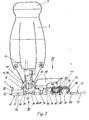
- the saw blade 5 of the jigsaw according to the invention is laterally supported and stabilized several times to achieve a straight cut.
- a guide or pressure roller 35 which is supported against the back of the saw blade 5.
- the saw blade 5 is not shown in FIG. 2 for the sake of clarity.
- the pressure roller 35 is arranged at a distance above the saw table 1. It is held by supports 36 which are connected to the motor head 2.
- the carriers 36 can in particular be articulated to the motor head 2 and be under the force of a compression spring which tensions the pressure roller 35 against the saw blade 5 (not shown).
- the guide or pressure roller 35 itself is rotatably supported between the carriers 36. In a central arrangement, it has an annular groove 37, the width of which corresponds to the thickness of the saw blade 5 plus a small amount of running play. The back of the saw blade 5 engages in this annular groove 37 so that the saw blade 5 is laterally stabilized between the flanks of the groove.
- the pressure roller 35 executes a derived rotary movement in accordance with the up and down movement of the saw blade 5, and its holder is optionally designed to follow a pendulum stroke of the saw blade 5.
- the pressure roller 35 primarily has the function of an abutment, which counteracts a deflection of the saw blade 5 to the rear and to the side when cutting. The lateral stabilizing effect of the guide or pressure roller 35 is satisfied, but not fully due to its arrangement above the outsole 6 of the saw table.
- the invention provides an additional lateral guidance of the saw blade 5 at the height of the saw table 1 directly above the outsole 6. 4 to 6, two stabilizing elements 38 are used for this purpose, which act on both sides against the flanks of the saw blade 5.
- the stabilizing elements 38 are blocks made of a material that can withstand high thermal loads, in particular oxide ceramics such as aluminum oxide ceramics. These Blocks can be placed against the saw blade 5 in a wide variety of ways in order to prevent the saw blade from bending on the exit side of the cut and to limit the lateral deflection movement of the saw blade 5.
- the stabilizing elements 38 are screwed to the base plate 10 of the saw table 1.
- a web 39 is integrally formed on the foot plate 10 and extends transversely to the longitudinal direction of the foot plate 10 and spans the recess 14 in which the saw blade 5 runs.
- the web 39 comes to lie behind the back of the saw blade 5.
- It has a rounded-rectangular cross section and is provided with two threaded bores 40, which are located in a symmetrical arrangement on both sides of the longitudinal center plane of the base plate 10 and are directed perpendicular to the saw table plane.
- the threaded bores 40 are used to fasten one stabilizing element 38 each.
- the stabilizing elements have an essentially rectangular plan (cf. FIG. 5).
- this running gap 41 is preferably chosen so that the stabilizing elements 38 work laterally against the non-toothed part of the saw blade 5, i.e. do not touch the cutting edges of the saw blade 5.
- the stabilizing elements. 38 In the side view (Fig. 6) have the stabilizing elements. 38 a U-profile. They fit with the U opening 42 on the web 39, to which they are screwed from the underside of the saw table 1. There is an adjustment possibility in the saw table plane transverse to the cutting direction of the saw blade 5.
- the stabilizing elements 38 are provided with corresponding elongated holes 43 through which the shaft of their mounting screws 44 passes. They can be adjusted laterally in the slot play on the web 39, which enables tolerance compensation and compensation of different saw blade thicknesses Lich and the game of the saw blade 5 between the stabilizing elements 38 can be adjusted.
- the running shoe 11 is cut out in the area of the stabilizing elements 38 in a shape which corresponds to that of the recess 14 in the footplate 10.
- the stabilizing elements 38 are therefore of the. Underside of the saw table 1 accessible even when the running shoe 1 is screwed on. Arrow 45 in FIG. 6 indicates how the stabilizing elements 38 are placed on the web 39. It can be seen that the mounted stabilizing elements protrude beyond the base of the footplate 10, but come to rest sunk in the running shoe 11. This ensures a minimum distance between the outsole 6 and the lower edge 46 of the stabilizing elements 38.
- the stabilizing elements 38 are preceded by a splinter guard or chip catch 47 in which the cutting edges of the saw blade 5 run.
- the chip catch 47 consists of a soft material, in particular plastic, into which the saw blade 5 cuts free to create a running gap.
- the splinterguard must be pressed into the running saw blade with your thumb, for example.
- the chip catch 47 is held by the base plate 10 of the saw table 1. It spans the recess 14 in which the saw blade 5 runs and is adjustable in the longitudinal direction of the saw table 1.
- Two ribs 48 are used to guide the chip catch 47, which are integrally formed on the base plate 10 and project laterally into the recess 14 opposite one another. The arrangement of the ribs 48 results in detail from FIGS.
- the ribs 48 accordingly have an essentially rectangular cross section. They start on the front narrow side 13 of the foot plate 10 with a bevel 49 which facilitates the pulling up of the chip catch 47 and narrows towards the saw blade 5, and they extend parallel to the saw table plane up to just before the web 39.
- the ribs 48 engage in complementary guide grooves 50 on the two side walls 51 of the chip catch 47 (cf. FIGS. 6 and 7).
- the chip catch 47 can be moved on the ribs 48 into an abutment position with the stabilizing elements 38, the saw blade 5 sawing a running gap into the chip catch 47.
- the direction in which the chip catch 47 is pushed open is illustrated in FIG. 6 by the arrow 52.
- the figure shows that the chip catch 47 protrudes in the assembled state over the base 53 of the footplate 10, but comes to rest sunk in the running shoe 11, so that its underside 54 is flush with the outsole 6 or at a very short distance above the outsole 6 comes to rest.
- the soft material of the chip catch 47 prevents parts of the cut material from splintering off at the exit point of the saw blade 5, as a result of which a very clean cut is achieved and minimal chip waste occurs.
- Controlling the chip flight is highly desirable so that a slight play between the stabilizing elements 38 and the saw blade 5 can be set. It must be prevented as far as possible that chips get between the saw blade 5 and the stabilizing elements 38, where they brake the run of the saw blade and can lead to increased wear and tear.
- the profile of the chip catch 47 / the effective dust extraction according to the invention likewise contribute to this. 5 to 7, a triangular cutout 56 is provided on the front edge 55 of the splinterguard or chip catch 47 in a central arrangement, the tip of which points towards the saw blade 5 and serves as a cut display or as an indication of the position of the saw blade during sawing by making it easier to precisely guide the jigsaw along a crack.
- the chip removal channels 57 In front of the tip of the cutout 56 two chip removal channels 57 exit, which are cut out on the underside 54 of the chip catch 47 (cf. FIGS. 5 and 7).
- the chip removal channels 57 lead to the rear edge 58 of the chip catch 47, whereby they diverge in a triangular configuration and end at the side edge of the chip catch 47.
- the amount of spen produced on the underside of the saw table 1, which is already small, is thus carried away laterally from the stabilizing elements 38.
- the stabilizing elements 38 are dimensioned such that they do not occupy the full width or the full depth of the recess 14 in the saw table 1.
- the stabilizing elements 38 are firmly connected to the saw table 1 and can only be adjusted in the saw table plane. It is therefore clear that the stabilizing elements do not participate in a pivoting movement of the motor head 2, so that they can only be used with a vertical saw cut. However, a modification is also conceivable in which the stabilizing elements 38 are tapered at the ends facing one another, wherein the saw blade can be pivoted between the facing tips.
- the material thickness of the chip catch 47 in the working area of the saw blade 5 is reduced by a depression 63.
- the guide in the saw table 1 is carried out on lateral tabs 64 which extend on both sides of the depression 63 and in which the guide grooves 50 are recessed. This arrangement primarily serves to lower the chip catch 47 to the required depth relative to the base plate 10 so that it is approximately flush with the outsole 6.
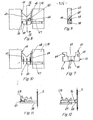
- This design is structurally very inexpensive. However, it does not offer any adjustment options for the stabilizing elements 38. In general, therefore, an arrangement is preferred in which the stabilizing elements 38 can be adjusted and fixed transversely to the plane of the saw blade, the guidance of the stabilizing elements 38 equally on the saw table 1 (cf. FIGS. 4 to 6) ) can also take place on the chip catch 47. Examples of the latter design are shown in FIGS. 8 to 10. The chip catch 47 is guided on the saw table 1 in the manner described above.
- the chip catch 47 on its rear edge facing the saw blade 5 has a guide groove 65 on either side of the longitudinal center plane, which can have the shape of a round groove, T-groove or dovetail groove, for example.
- the guide grooves 65 extend in the saw table plane transversely to the cutting direction of the saw blade 5, they are designed as blind grooves.
- the central region of the chip catch 47 between the guide grooves 65 is solid, so that the saw blade 5 can cut a running gap here.
- the saw blade 5 is guided between two stabilizing elements 38 which are carried by the chip catch 47.
- the stabilizing elements start at the back of the chip catch 47 and they are flush with the chip catch 47 at the top and bottom.
- a guide head 66 is formed, which has a complementary shape to the guide groove 65 and engages in this.
- the stabilizing elements 38 can be adjusted transversely to the saw blade plane and positioned against the saw blade 5.
- the necessary holding force is applied by two screws 67 which are put into threaded holes of the saw table 1 up 'and the stabilizing elements 38 beaufschla - gen.
- the stebilizing elements 38 are held on resilient support arms 68, which enable adjustment transverse to the saw blade plane.
- the stabilizing elements 38 are in turn acted upon by adjusting screws 67 which screw in the saw table 1.
- the support arms 68 are anchored in the chip catch 47, and in particular are cast into the plastic material of the chip catch 47.
- the resilient support arms 68 can also be attached to the saw table 1 if necessary.
- FIGS. 11 and 12 show further exemplary embodiments of the stabilizing elements 38 which work laterally against the saw blade 5.
- these have the shape of a ceramic slide which is mounted in the saw table 1 so as to be displaceable transversely to the saw blade plane. The slides are acted upon by adjusting screws 67 and are turned on against the saw blade 5.
- a ceramic plate 69 serves as a stabilizing element, which is non-releasably rigidly connected to the front end face 70 of an adjusting screw 67, and in particular is glued onto this end face.
- the distance between the stabilizing element and the saw blade can be adjusted by turning the adjusting screw 67.
- the straight cut of a jigsaw significantly improved.
- This result can be further promoted by using a thicker saw blade.
- conventional jigsaw blades have a maximum thickness of 1.35 mm
- the invention provides for the use of saw blades 5 with more than 1.35 mm and up to 2 mm thickness, a preferred value being 1.75 mm.
- the thickness By increasing the thickness to 1.75 mm, the bending stiffness of the saw blade 5 increases by 118%, and the cutting accuracy of the saw is improved accordingly.
- the cutting performance decreases somewhat due to the larger machining volume, this reduction in cutting performance is only insignificant.
- the invention provides for the use of a guide plate which can be placed on the workpiece to be cut and which determines the course of the saw cut.
- a guide L plate 71 is shown in Fig. 2. It consists of a flat support part 72, on which an upwardly projecting rail 73 with parallel guide surfaces 74, 75 is formed.
- the guide plate 71 can be made of sheet metal, for example, and the rail 73 can be produced as a bead by embossing (not shown).
- the connection between the saw table 1 and the guide plate 71 is made according to FIGS. 2 and 3 with an intermediate piece 76.
- the intermediate piece 76 is an L-profile in the basic form. Its long L-leg 77 is on the saw table 1 determined what z. B. can be done by eccentric clamping.
- a gag 78 can be seen, which is rotatably mounted in the long L-leg 77 and is connected to an eccentric 79.
- the eccentric 79 works against an abutment in the saw table 1, so that the L-leg 77 is clamped against the saw table 1 by turning the toggle 78.
- the saw table 1 is provided on both sides of the attachment 17 with attachment points for the intermediate piece 76, so that it can optionally be mounted on both sides of the jigsaw.
- the intermediate piece 76 protrudes laterally from the saw table 1, the long L-leg 77 coming to lie at such a distance from the outsole 6 that it overlaps the rail 73.
- two pins 79a, 79b are also provided on the intermediate piece, which can be inserted into the bores 80a and 80b or 81a and 81b.
- the short L-leg 80 is angled downwards. It comes to rest with the one guide surface 75 of the rail 73.
- the opposite guide surface 74 is acted upon by two actuators 81, which are attached to the long L-leg 77 offset in the longitudinal direction.
- a two-point guidance of the intermediate piece 76 on the rail 73 is achieved with the actuators 81, wherein the guide play can be adjusted.
- the actuators 81 each consist of a slotted plastic body 82 which is fastened to the long L-leg 77 with mounting screws 83.
- the slot in the plastic body 82 is identified at 84. It extends in the longitudinal direction of the rail 73 and divides a cheek 85 into the plastic body 82, which cheek is elastically deformable due to its thickness.
- the cheek 85 is acted upon by an adjusting screw 86, which is received in a threaded bore of the plastic body 82, passes through the slot 84 and becomes itself screwed transversely to the longitudinal direction of the rail 73.
- the set screw 86 presses the cheek 85 against the guide surface 74 of the rail 73.
- the back of the cheek 85, against which the set screw 86 works, can be backed up in a manner not shown with a preferably resilient metal bracket.
- the running play of the intermediate piece 76 on the rail 73 is set by the deformation of the cheek 85.
- the long L-leg 77 of the intermediate piece 76 is broken open in the region of the cheek 85, and the cheeks 85 protrude with an extension 87 into the corresponding column 88.
- the deflection of the cheeks 85 is limited by a stop, and simple visual control of the respective setting is possible.
- the two contact points of the actuator 81 can thus be compared with one another in an advantageous manner.
- the eccentric clamping of the intermediate piece 76 is seen in the longitudinal direction between the two actuators 81.
- the long L-leg 77 can be narrowed in this area, as shown in FIG. 3.
- FIG. 13 An alternative design of a guide plate 71 is illustrated in FIG. 13.
- the guide plate 71 also has a support part 72, on the underside of which a non-slip covering 89 is provided.
- a rail 73 which provides a lateral guide surface 74, is formed on the support part 72.
- the rail 73 is located on one longitudinal edge of the support part 72.
- the opposite edge of the guide plate 71 is formed by an upwardly projecting web 90, the inside 91 of which is designed as a second guide surface.
- the saw table 1 is placed between the rail 73 and the web 90 on the guide plate 71 and moved in the longitudinal direction of the guide plate 71. It can be seen that the saw table 1 is gripped on both sides by the guide plate 71.
- the lead tion plate 71 is slotted at 92 in the longitudinal direction to allow passage of the saw blade 5.
- the saw blade 5 works close to the edge 92 of the passage gap 92, which is preferably formed by the edge of the non-slip covering 89.
- the guide plate 71 can thus be precisely aligned in accordance with the desired cutting line.
Landscapes
- Engineering & Computer Science (AREA)
- Mechanical Engineering (AREA)
- Life Sciences & Earth Sciences (AREA)
- Wood Science & Technology (AREA)
- Forests & Forestry (AREA)
- Sawing (AREA)
- Dry Formation Of Fiberboard And The Like (AREA)
- Container, Conveyance, Adherence, Positioning, Of Wafer (AREA)
- Heat Treatment Of Articles (AREA)
- Sampling And Sample Adjustment (AREA)
Priority Applications (1)
| Application Number | Priority Date | Filing Date | Title |
|---|---|---|---|
| AT85105810T ATE65445T1 (de) | 1984-06-01 | 1985-05-11 | Stichsaege. |
Applications Claiming Priority (2)
| Application Number | Priority Date | Filing Date | Title |
|---|---|---|---|
| DE3420442 | 1984-06-01 | ||
| DE3420442A DE3420442A1 (de) | 1984-06-01 | 1984-06-01 | Stichsaege |
Publications (3)
| Publication Number | Publication Date |
|---|---|
| EP0163185A2 true EP0163185A2 (fr) | 1985-12-04 |
| EP0163185A3 EP0163185A3 (en) | 1988-06-15 |
| EP0163185B1 EP0163185B1 (fr) | 1991-07-24 |
Family
ID=6237377
Family Applications (2)
| Application Number | Title | Priority Date | Filing Date |
|---|---|---|---|
| EP85105810A Expired - Lifetime EP0163185B1 (fr) | 1984-06-01 | 1985-05-11 | Scie sauteuse |
| EP85105813A Expired - Lifetime EP0163186B1 (fr) | 1984-06-01 | 1985-05-11 | Scie sauteuse pour travailler des pièces, par exemple en bois, en matière plastique ou en métal |
Family Applications After (1)
| Application Number | Title | Priority Date | Filing Date |
|---|---|---|---|
| EP85105813A Expired - Lifetime EP0163186B1 (fr) | 1984-06-01 | 1985-05-11 | Scie sauteuse pour travailler des pièces, par exemple en bois, en matière plastique ou en métal |
Country Status (5)
| Country | Link |
|---|---|
| US (1) | US4665617A (fr) |
| EP (2) | EP0163185B1 (fr) |
| JP (2) | JPH0720601B2 (fr) |
| AT (1) | ATE65445T1 (fr) |
| DE (1) | DE3420442A1 (fr) |
Cited By (4)
| Publication number | Priority date | Publication date | Assignee | Title |
|---|---|---|---|---|
| DE4310691A1 (de) * | 1993-04-01 | 1994-10-06 | Thomas Holst | Absaugvorrichtung für Bandsägen |
| EP0709156A1 (fr) * | 1994-10-28 | 1996-05-01 | Black & Decker Inc. | Scie sauteuse |
| CN112548226A (zh) * | 2020-12-16 | 2021-03-26 | 湖北铭宇水晶饰品有限公司 | 一种用于水钻抛光滚筒的内壁防滑纹加工装置 |
| CN116600926A (zh) * | 2020-10-28 | 2023-08-15 | 费斯托工具有限责任公司 | 吸走装置以及装备有其的手持式锯切机器 |
Families Citing this family (68)
| Publication number | Priority date | Publication date | Assignee | Title |
|---|---|---|---|---|
| DE3613279A1 (de) * | 1986-04-19 | 1987-10-22 | Festo Kg | Stichsaege |
| DE3712236A1 (de) * | 1987-04-10 | 1988-10-27 | Bosch Gmbh Robert | Stichsaege |
| US5038481A (en) * | 1990-05-04 | 1991-08-13 | Lonnie Smith | Saber saw tracking light |
| DE4027135C2 (de) * | 1990-08-28 | 1995-09-07 | Gerhard Netz | Stichsäge mit Drehzahlregelung |
| AU650533B2 (en) * | 1991-05-09 | 1994-06-23 | Tool Concepts Pty Ltd | Cutting tool |
| JPH065902U (ja) * | 1991-10-18 | 1994-01-25 | 文映 杉山 | 鋸 |
| RU2104832C1 (ru) * | 1992-01-14 | 1998-02-20 | Роберт Бош Гмбх | Устройство для защиты от стружки на лесопильном станке с пильным полотном |
| DE4224094A1 (de) * | 1992-07-22 | 1994-01-27 | Bosch Gmbh Robert | Handsäge mit Absaugvorrichtung |
| DE4302674A1 (de) * | 1993-01-30 | 1994-08-18 | Bosch Gmbh Robert | Elektrohandsäge, insbesondere Schwertsäge |
| DE4316155C2 (de) * | 1993-05-14 | 1996-04-04 | Kress Elektrik Gmbh & Co | Sägetisch für eine Stichsäge |
| JP3251456B2 (ja) * | 1995-03-10 | 2002-01-28 | 株式会社マキタ | ジグソーの吸塵装置 |
| DE19513076A1 (de) * | 1995-04-07 | 1996-10-10 | Scintilla Ag | Stichsäge |
| US5837040A (en) * | 1996-09-09 | 1998-11-17 | International Decontamination Systems Llc | Room air decontamination device |
| US5890954A (en) * | 1996-11-06 | 1999-04-06 | Barous; Francis A. | Floor edgers and sanders |
| US6178646B1 (en) | 1998-07-10 | 2001-01-30 | Porter-Cable Corporation | Blade clamping system for a jigsaw |
| US6230411B1 (en) | 1998-07-10 | 2001-05-15 | Porter-Cable Corporation | Blade guide system for a jigsaw |
| US6357124B1 (en) | 1998-07-10 | 2002-03-19 | Porter-Cable Corporation | Clamp system for a jigsaw tilt base |
| US6094826A (en) * | 1998-09-01 | 2000-08-01 | Hobbico, Inc. | Reciprocating slot cutting tool |
| AU2001249433A1 (en) * | 2000-03-27 | 2001-10-08 | Clifford D. Hyatt | Ceramic guide block and method of manufacture |
| US20020046469A1 (en) * | 2000-09-14 | 2002-04-25 | Dilaura Karen M. | Composite material platen for portable wood working machine |
| DE10045890A1 (de) * | 2000-09-16 | 2002-04-04 | Bosch Gmbh Robert | Säge mit einem Werkzeugführungsmechanismus |
| JP4248766B2 (ja) * | 2001-05-23 | 2009-04-02 | 株式会社マキタ | 往復動切断工具 |
| GB2399315A (en) * | 2003-03-13 | 2004-09-15 | Black & Decker Inc | Method and apparatus for removing dust from a workpiece |
| GB2399537A (en) * | 2003-03-13 | 2004-09-22 | Black & Decker Inc | Method and apparatus for removing dust from a workpiece |
| GB2405829A (en) * | 2003-09-09 | 2005-03-16 | Black & Decker Inc | Reciprocating saw and guard rail assembly therefor |
| GB2415660A (en) * | 2004-06-29 | 2006-01-04 | Black & Decker Inc | Shoe assembly for power tool |
| USD505851S1 (en) * | 2003-09-17 | 2005-06-07 | Gmca Pty Limited | Jigsaw |
| DE10357841B4 (de) * | 2003-12-11 | 2012-12-06 | Hilti Aktiengesellschaft | Stichsäge mit Sauganschlussanordnung |
| US20050178260A1 (en) * | 2004-02-13 | 2005-08-18 | Bokelaar Willibrordus G. | Saw guide system |
| US20060037445A1 (en) * | 2004-08-18 | 2006-02-23 | Sergyeyenko Oleksiy P | Circular saw with laser and protractor |
| US7430810B2 (en) | 2004-08-18 | 2008-10-07 | Black & Decker Inc. | Laser square protractor kit |
| US20060064882A1 (en) * | 2004-09-28 | 2006-03-30 | Mike Wilson | Reciprocationg saw and guard rail assembly therefor |
| DE102005025934C5 (de) * | 2005-06-06 | 2020-10-22 | Mafell Ag | Elektrische Stichsäge |
| DE602006004552D1 (de) * | 2006-03-18 | 2009-02-12 | Black & Decker Inc | Stichsäge mit Vorrichtung zur Späneabfuhr |
| DE102006000200A1 (de) * | 2006-04-27 | 2007-10-31 | Hilti Ag | Elektrohandsäge mit Absaugvorrichtung |
| DE102006030558A1 (de) * | 2006-07-03 | 2008-01-10 | Robert Bosch Gmbh | Handhubsägemaschine |
| DE102007025967A1 (de) * | 2007-06-04 | 2008-12-11 | Robert Bosch Gmbh | Pendelführungseinrichtung für ein Hubbewegungen durchführendes Sägeblatt einer Hubsägemaschine |
| DE102007034529A1 (de) * | 2007-07-25 | 2009-01-29 | Robert Bosch Gmbh | Handwerkzeugmaschine |
| DE102007038979B3 (de) | 2007-08-17 | 2009-03-12 | Festool Gmbh | Vorsatzgerät für eine Hubsäge |
| US10029322B2 (en) * | 2007-09-21 | 2018-07-24 | Black & Decker Inc. | Housing of a cutting tool including blade storage, integral blade guard and motor ventilation pathway |
| US20090077819A1 (en) * | 2007-09-21 | 2009-03-26 | Black & Decker Inc. | Cutting Angle Indicator in Jigsaw Housing with Positive Lock in Separately Assembled Shoe Sub-Assembly |
| US9827623B2 (en) | 2007-09-21 | 2017-11-28 | Black & Decker Inc. | Control of reciprocation speed and orbital magnitude of a jigsaw with a plurality of material and/or task descriptive icons |
| US8033026B2 (en) * | 2007-09-21 | 2011-10-11 | Black & Decker Inc. | Adjustable and removable keel assembly and blade guide for a jigsaw |
| US9981327B2 (en) * | 2007-09-21 | 2018-05-29 | Black & Decker Inc. | Cutting angle indicator in jigsaw housing with dust extraction |
| DE102007049708A1 (de) * | 2007-10-17 | 2009-04-23 | Robert Bosch Gmbh | Gebaute Fußplatte für handgeführte Werkzeugmaschinen |
| DE102007057531A1 (de) * | 2007-11-29 | 2009-06-04 | Mafell Ag | Elektrowerkzeug |
| JP2009142978A (ja) * | 2007-12-12 | 2009-07-02 | Hilti Ag | モータ駆動の往復鋸装置 |
| US8230607B2 (en) * | 2008-05-09 | 2012-07-31 | Milwaukee Electric Tool Corporation | Keyless blade clamp for a power tool |
| WO2009149194A1 (fr) | 2008-06-03 | 2009-12-10 | Milwaukee Electric Tool Corporation | Accessoire de sabot pour une scie |
| JP5330788B2 (ja) * | 2008-09-30 | 2013-10-30 | パナソニック株式会社 | 切断工具 |
| DE102009055860A1 (de) | 2009-11-26 | 2011-06-09 | Festool Gmbh | Hand-Werkzeugmaschine und Gleitsohle mit einer Gleitstruktur |
| DE102009055827A1 (de) | 2009-11-26 | 2011-06-01 | Festool Gmbh | Hand-Werkzeugmaschine mit einer Gleitsohle |
| JP5620709B2 (ja) * | 2010-04-28 | 2014-11-05 | 株式会社マキタ | 切断工具 |
| JP5526003B2 (ja) * | 2010-11-19 | 2014-06-18 | 株式会社マキタ | 切断機 |
| DE102011005036A1 (de) * | 2011-03-03 | 2012-09-06 | Robert Bosch Gmbh | Tragbare Werkzeugmaschine |
| US8578615B2 (en) | 2011-09-12 | 2013-11-12 | Black & Decker Inc. | Jigsaw with deployable keel and tiltable shoe |
| JP5855519B2 (ja) * | 2012-04-24 | 2016-02-09 | リョービ株式会社 | 電動工具 |
| JP2014004666A (ja) * | 2012-06-26 | 2014-01-16 | Makita Corp | ジグソー |
| JP6295128B2 (ja) * | 2013-06-20 | 2018-03-14 | 株式会社マキタ | ジグソー |
| JP2015062977A (ja) * | 2013-09-25 | 2015-04-09 | 日立工機株式会社 | 往復動工具 |
| WO2015050055A1 (fr) * | 2013-10-01 | 2015-04-09 | 日立工機株式会社 | Outil de coupe |
| US9559628B2 (en) | 2013-10-25 | 2017-01-31 | Black & Decker Inc. | Handheld power tool with compact AC switch |
| US10654188B2 (en) * | 2014-12-31 | 2020-05-19 | Robert Bosch Tool Corporation | Guide foot for an oscillating cutting tool |
| US10486251B2 (en) * | 2016-05-16 | 2019-11-26 | Makita Corporation | Machining devices |
| DE102019220365A1 (de) * | 2019-12-20 | 2021-06-24 | Robert Bosch Gesellschaft mit beschränkter Haftung | Sägewerkzeug |
| DE102021210575A1 (de) * | 2021-09-23 | 2023-03-23 | Robert Bosch Gesellschaft mit beschränkter Haftung | Sägeblattführungsvorrichtung für eine Säge und Säge mit der Sägeblattführungsvorrichtung |
| DE102021215115A1 (de) | 2021-12-30 | 2023-07-06 | Robert Bosch Gesellschaft mit beschränkter Haftung | Zangenführung für eine Stichsäge |
| CH721171A2 (fr) * | 2023-10-03 | 2025-04-15 | Stephanie Portmann | Module de délignage pour scie électroportative et scie électroportative |
Family Cites Families (29)
| Publication number | Priority date | Publication date | Assignee | Title |
|---|---|---|---|---|
| US2736203A (en) | 1956-02-28 | shore | ||
| US1690808A (en) | 1928-02-04 | 1928-11-06 | Appelbaum Isaac | Cloth-cutting machine |
| US2369925A (en) * | 1944-02-24 | 1945-02-20 | Samuel B Smith | Surgical instrument for bone cutting |
| GB778019A (en) * | 1955-08-04 | 1957-07-03 | Armstrong Whitworth Co Eng | Improved motor-driven hand-saw |
| US2984757A (en) * | 1956-06-28 | 1961-05-16 | Walter A Papworth | Manually portable tool construction |
| US2902067A (en) * | 1957-04-22 | 1959-09-01 | Oakley Products Company | Reciprocating saw |
| US2996089A (en) | 1960-08-25 | 1961-08-15 | Black & Decker Mfg Co | Self-aligning anti-splintering insert for shoe of jig saw |
| US3033252A (en) * | 1960-09-15 | 1962-05-08 | Black & Decker Mfg Co | Air passage means for recipro-cating saw |
| US3038508A (en) | 1960-09-21 | 1962-06-12 | Lawrence J Moran | Guide for jigsaw blade |
| US3303861A (en) * | 1964-07-06 | 1967-02-14 | Rockwell Mfg Co | Saw structure |
| US3339598A (en) | 1964-08-12 | 1967-09-05 | Rockwell Mfg Co | Saw structures |
| JPS44719Y1 (fr) * | 1965-05-07 | 1969-01-13 | ||
| US3586077A (en) * | 1969-07-03 | 1971-06-22 | Mason E Pease | Cutting guide means for a portable powersaw |
| US3643536A (en) | 1970-06-01 | 1972-02-22 | Wells Mfg Corp | Self-adjusting roller guide |
| JPS50113092U (fr) * | 1974-02-22 | 1975-09-16 | ||
| US3938251A (en) * | 1975-03-10 | 1976-02-17 | The Raymond Lee Organization, Inc. | Saber or jig saw with demountable foot plate and shield |
| DE2546527C2 (de) | 1975-10-17 | 1993-05-27 | Robert Bosch Gmbh, 7000 Stuttgart | Stichsäge |
| DE2546529B2 (de) * | 1975-10-17 | 1979-02-08 | Robert Bosch Gmbh, 7000 Stuttgart | Schaltungsanordnung zum Regeln der Fahrgeschwindigkeit eines Kraftfahrzeuges |
| US4091701A (en) * | 1976-11-01 | 1978-05-30 | Gerber Garment Technology, Inc. | Cutting machine having roller blade guide |
| JPS53120393U (fr) * | 1977-03-03 | 1978-09-25 | ||
| JPS5593501U (fr) * | 1978-10-16 | 1980-06-28 | ||
| US4195403A (en) * | 1979-05-09 | 1980-04-01 | Gruber Clarence R | Sawdust removal device |
| US4240204A (en) * | 1979-06-19 | 1980-12-23 | Black & Decker Inc. | Jig saw |
| JPS5610490U (fr) * | 1979-07-04 | 1981-01-29 | ||
| JPS5641601U (fr) * | 1979-09-07 | 1981-04-16 | ||
| DE3021801C2 (de) | 1980-06-11 | 1985-03-21 | Licentia Patent-Verwaltungs-Gmbh, 6000 Frankfurt | Stichsäge mit am Sägengehäuse befestigbarem Auflagetisch |
| US4334356A (en) * | 1980-07-14 | 1982-06-15 | Peter Krosunger | Anti-mar base for saber- and bayonet-type saws and the like |
| DE8024714U1 (de) * | 1980-09-16 | 1982-02-04 | Robert Bosch Gmbh, 7000 Stuttgart | Führungsvorrichtung für eine Handwerkzeugmaschine |
| DE3218657C1 (de) | 1982-05-18 | 1983-12-15 | Festo-Maschinenfabrik Gottlieb Stoll, 7300 Esslingen | Führungseinrichtung für eine Stichsäge |
-
1984
- 1984-06-01 DE DE3420442A patent/DE3420442A1/de active Granted
-
1985
- 1985-05-11 EP EP85105810A patent/EP0163185B1/fr not_active Expired - Lifetime
- 1985-05-11 AT AT85105810T patent/ATE65445T1/de not_active IP Right Cessation
- 1985-05-11 EP EP85105813A patent/EP0163186B1/fr not_active Expired - Lifetime
- 1985-05-28 US US06/738,680 patent/US4665617A/en not_active Expired - Fee Related
- 1985-06-01 JP JP60119640A patent/JPH0720601B2/ja not_active Expired - Lifetime
- 1985-06-01 JP JP60119639A patent/JPS60262602A/ja active Granted
Cited By (5)
| Publication number | Priority date | Publication date | Assignee | Title |
|---|---|---|---|---|
| DE4310691A1 (de) * | 1993-04-01 | 1994-10-06 | Thomas Holst | Absaugvorrichtung für Bandsägen |
| EP0709156A1 (fr) * | 1994-10-28 | 1996-05-01 | Black & Decker Inc. | Scie sauteuse |
| CN116600926A (zh) * | 2020-10-28 | 2023-08-15 | 费斯托工具有限责任公司 | 吸走装置以及装备有其的手持式锯切机器 |
| CN112548226A (zh) * | 2020-12-16 | 2021-03-26 | 湖北铭宇水晶饰品有限公司 | 一种用于水钻抛光滚筒的内壁防滑纹加工装置 |
| CN112548226B (zh) * | 2020-12-16 | 2023-06-30 | 湖北铭宇水晶饰品有限公司 | 一种用于水钻抛光滚筒的内壁防滑纹加工装置 |
Also Published As
| Publication number | Publication date |
|---|---|
| ATE65445T1 (de) | 1991-08-15 |
| EP0163185B1 (fr) | 1991-07-24 |
| EP0163185A3 (en) | 1988-06-15 |
| JPS60262602A (ja) | 1985-12-26 |
| DE3420442C3 (fr) | 1992-05-07 |
| DE3420442A1 (de) | 1985-12-05 |
| JPH0720601B2 (ja) | 1995-03-08 |
| JPH0371241B2 (fr) | 1991-11-12 |
| DE3420442C2 (fr) | 1987-11-19 |
| EP0163186B1 (fr) | 1992-02-26 |
| EP0163186A3 (en) | 1988-06-15 |
| US4665617A (en) | 1987-05-19 |
| JPS60262601A (ja) | 1985-12-26 |
| EP0163186A2 (fr) | 1985-12-04 |
Similar Documents
| Publication | Publication Date | Title |
|---|---|---|
| EP0163185A2 (fr) | Scie sauteuse | |
| DE3509515C2 (fr) | ||
| DE4106635C1 (fr) | ||
| EP0242519A2 (fr) | Scie sauteuse | |
| DE102007015805B4 (de) | Schneidsatz für elektrische Haarschneidemaschinen | |
| DE3428436A1 (de) | Tragbare stichsaege | |
| DE3447933C2 (fr) | ||
| DE8803627U1 (de) | Als Tauchsäge ausgebildete Handkreissäge | |
| DE2601858B2 (de) | Stanzmaschine | |
| DE4322303A1 (de) | Handwerkzeugmaschine | |
| EP1851017B1 (fr) | Regle d'arret pour scies circulaires a table | |
| WO1986005427A1 (fr) | Scie sauteuse | |
| DE8507818U1 (de) | Stichsäge | |
| DE102005025934C5 (de) | Elektrische Stichsäge | |
| DE3546700C2 (en) | Portable power fret saw | |
| DE19938106C1 (de) | Motorgetriebenes Handwerkzeug mit Anschlag | |
| DE814117C (de) | Haarschneidemaschine | |
| DE8906511U1 (de) | Stichsäge | |
| DE3428445C3 (de) | Verwendung eines zur Befestigung eines Sägeblattes an einer Hubstange einer Stichsäge vorgesehenen Druckstückes | |
| DE3448171C2 (en) | Guide device for a jigsaw | |
| DE19708601A1 (de) | Reib- und Senk-Schneidwerkzeug | |
| DE20100087U1 (de) | Handkreissäge | |
| EP2002912B1 (fr) | Table en porte-à-faux pour une scie à deligner ou une scie à panneaux | |
| DE3601811C1 (en) | File which can be secured to the tool holder of a jigsaw which can be used in particular in stationary operation | |
| DE20009747U1 (de) | Tischkreissäge |
Legal Events
| Date | Code | Title | Description |
|---|---|---|---|
| PUAI | Public reference made under article 153(3) epc to a published international application that has entered the european phase |
Free format text: ORIGINAL CODE: 0009012 |
|
| AK | Designated contracting states |
Designated state(s): AT CH FR GB IT LI SE |
|
| PUAL | Search report despatched |
Free format text: ORIGINAL CODE: 0009013 |
|
| AK | Designated contracting states |
Kind code of ref document: A3 Designated state(s): AT CH FR GB IT LI SE |
|
| 17P | Request for examination filed |
Effective date: 19881027 |
|
| 17Q | First examination report despatched |
Effective date: 19890421 |
|
| ITF | It: translation for a ep patent filed | ||
| GRAA | (expected) grant |
Free format text: ORIGINAL CODE: 0009210 |
|
| AK | Designated contracting states |
Kind code of ref document: B1 Designated state(s): AT CH FR GB IT LI SE |
|
| PG25 | Lapsed in a contracting state [announced via postgrant information from national office to epo] |
Ref country code: SE Effective date: 19910724 Ref country code: FR Effective date: 19910724 |
|
| REF | Corresponds to: |
Ref document number: 65445 Country of ref document: AT Date of ref document: 19910815 Kind code of ref document: T |
|
| GBT | Gb: translation of ep patent filed (gb section 77(6)(a)/1977) | ||
| EN | Fr: translation not filed | ||
| PLBI | Opposition filed |
Free format text: ORIGINAL CODE: 0009260 |
|
| PG25 | Lapsed in a contracting state [announced via postgrant information from national office to epo] |
Ref country code: AT Effective date: 19920511 |
|
| 26 | Opposition filed |
Opponent name: ROBERT BOSCH GMBH Effective date: 19920421 |
|
| PGFP | Annual fee paid to national office [announced via postgrant information from national office to epo] |
Ref country code: GB Payment date: 19930317 Year of fee payment: 9 |
|
| PGFP | Annual fee paid to national office [announced via postgrant information from national office to epo] |
Ref country code: CH Payment date: 19930713 Year of fee payment: 9 |
|
| RDAG | Patent revoked |
Free format text: ORIGINAL CODE: 0009271 |
|
| STAA | Information on the status of an ep patent application or granted ep patent |
Free format text: STATUS: PATENT REVOKED |
|
| 27W | Patent revoked |
Effective date: 19930910 |
|
| GBPR | Gb: patent revoked under art. 102 of the ep convention designating the uk as contracting state |
Free format text: 930910 |
|
| REG | Reference to a national code |
Ref country code: CH Ref legal event code: PL |