EP0163457A2 - Herstellung eines Lichtwellenleiters - Google Patents
Herstellung eines Lichtwellenleiters Download PDFInfo
- Publication number
- EP0163457A2 EP0163457A2 EP85303467A EP85303467A EP0163457A2 EP 0163457 A2 EP0163457 A2 EP 0163457A2 EP 85303467 A EP85303467 A EP 85303467A EP 85303467 A EP85303467 A EP 85303467A EP 0163457 A2 EP0163457 A2 EP 0163457A2
- Authority
- EP
- European Patent Office
- Prior art keywords
- fibre
- seal
- chamber
- gas
- sealing
- Prior art date
- Legal status (The legal status is an assumption and is not a legal conclusion. Google has not performed a legal analysis and makes no representation as to the accuracy of the status listed.)
- Granted
Links
- 239000013307 optical fiber Substances 0.000 title claims abstract description 12
- 238000004519 manufacturing process Methods 0.000 title claims description 8
- 239000000835 fiber Substances 0.000 claims abstract description 53
- 238000006243 chemical reaction Methods 0.000 claims abstract description 11
- 238000005229 chemical vapour deposition Methods 0.000 claims abstract description 4
- 239000007789 gas Substances 0.000 claims description 39
- IJGRMHOSHXDMSA-UHFFFAOYSA-N Atomic nitrogen Chemical compound N#N IJGRMHOSHXDMSA-UHFFFAOYSA-N 0.000 claims description 23
- 238000000034 method Methods 0.000 claims description 21
- 238000007789 sealing Methods 0.000 claims description 14
- 230000008569 process Effects 0.000 claims description 13
- 229910052757 nitrogen Inorganic materials 0.000 claims description 11
- 238000012545 processing Methods 0.000 claims description 7
- XUIMIQQOPSSXEZ-UHFFFAOYSA-N Silicon Chemical compound [Si] XUIMIQQOPSSXEZ-UHFFFAOYSA-N 0.000 claims description 6
- 229910052710 silicon Inorganic materials 0.000 claims description 6
- 239000010703 silicon Substances 0.000 claims description 6
- 230000008859 change Effects 0.000 claims description 2
- KJKKZSJXJPPWSI-UHFFFAOYSA-N n,6-dimethylhept-5-en-2-amine;1,5-dimethyl-2-phenylpyrazol-3-one;n-(4-hydroxyphenyl)acetamide;2,3,4,5-tetrahydroxyhexanedioic acid;2,2,2-trichloroethane-1,1-diol Chemical compound OC(O)C(Cl)(Cl)Cl.OC(O)C(Cl)(Cl)Cl.CNC(C)CCC=C(C)C.CC(=O)NC1=CC=C(O)C=C1.CN1C(C)=CC(=O)N1C1=CC=CC=C1.OC(=O)C(O)C(O)C(O)C(O)C(O)=O KJKKZSJXJPPWSI-UHFFFAOYSA-N 0.000 claims 1
- 238000004381 surface treatment Methods 0.000 claims 1
- 238000000576 coating method Methods 0.000 abstract description 20
- 239000011248 coating agent Substances 0.000 abstract description 14
- 229910052581 Si3N4 Inorganic materials 0.000 abstract description 10
- 230000007797 corrosion Effects 0.000 abstract description 9
- 238000005260 corrosion Methods 0.000 abstract description 9
- HQVNEWCFYHHQES-UHFFFAOYSA-N silicon nitride Chemical compound N12[Si]34N5[Si]62N3[Si]51N64 HQVNEWCFYHHQES-UHFFFAOYSA-N 0.000 abstract description 9
- 238000000151 deposition Methods 0.000 description 9
- 230000008021 deposition Effects 0.000 description 9
- BLRPTPMANUNPDV-UHFFFAOYSA-N Silane Chemical compound [SiH4] BLRPTPMANUNPDV-UHFFFAOYSA-N 0.000 description 8
- QGZKDVFQNNGYKY-UHFFFAOYSA-N Ammonia Chemical compound N QGZKDVFQNNGYKY-UHFFFAOYSA-N 0.000 description 7
- 230000004888 barrier function Effects 0.000 description 7
- 239000000376 reactant Substances 0.000 description 7
- XLYOFNOQVPJJNP-UHFFFAOYSA-N water Substances O XLYOFNOQVPJJNP-UHFFFAOYSA-N 0.000 description 6
- 238000000605 extraction Methods 0.000 description 5
- VYPSYNLAJGMNEJ-UHFFFAOYSA-N Silicium dioxide Chemical compound O=[Si]=O VYPSYNLAJGMNEJ-UHFFFAOYSA-N 0.000 description 4
- 239000000463 material Substances 0.000 description 4
- 238000010926 purge Methods 0.000 description 4
- 231100000331 toxic Toxicity 0.000 description 4
- 230000002588 toxic effect Effects 0.000 description 4
- 230000007547 defect Effects 0.000 description 3
- 238000009792 diffusion process Methods 0.000 description 3
- 239000003085 diluting agent Substances 0.000 description 3
- 229910000069 nitrogen hydride Inorganic materials 0.000 description 3
- 230000003287 optical effect Effects 0.000 description 3
- 229910000077 silane Inorganic materials 0.000 description 3
- NLXLAEXVIDQMFP-UHFFFAOYSA-N Ammonia chloride Chemical compound [NH4+].[Cl-] NLXLAEXVIDQMFP-UHFFFAOYSA-N 0.000 description 2
- MWUXSHHQAYIFBG-UHFFFAOYSA-N Nitric oxide Chemical compound O=[N] MWUXSHHQAYIFBG-UHFFFAOYSA-N 0.000 description 2
- PNEYBMLMFCGWSK-UHFFFAOYSA-N aluminium oxide Inorganic materials [O-2].[O-2].[O-2].[Al+3].[Al+3] PNEYBMLMFCGWSK-UHFFFAOYSA-N 0.000 description 2
- 229910021529 ammonia Inorganic materials 0.000 description 2
- 230000008901 benefit Effects 0.000 description 2
- 230000015556 catabolic process Effects 0.000 description 2
- 238000005524 ceramic coating Methods 0.000 description 2
- 238000006731 degradation reaction Methods 0.000 description 2
- 230000000694 effects Effects 0.000 description 2
- 238000013383 initial experiment Methods 0.000 description 2
- 229910052751 metal Inorganic materials 0.000 description 2
- 239000002184 metal Substances 0.000 description 2
- 238000001465 metallisation Methods 0.000 description 2
- 150000002739 metals Chemical class 0.000 description 2
- 238000002156 mixing Methods 0.000 description 2
- 239000002245 particle Substances 0.000 description 2
- 239000004065 semiconductor Substances 0.000 description 2
- 239000000377 silicon dioxide Substances 0.000 description 2
- 238000003860 storage Methods 0.000 description 2
- 238000012360 testing method Methods 0.000 description 2
- 238000004804 winding Methods 0.000 description 2
- VXEGSRKPIUDPQT-UHFFFAOYSA-N 4-[4-(4-methoxyphenyl)piperazin-1-yl]aniline Chemical compound C1=CC(OC)=CC=C1N1CCN(C=2C=CC(N)=CC=2)CC1 VXEGSRKPIUDPQT-UHFFFAOYSA-N 0.000 description 1
- -1 C02 Chemical compound 0.000 description 1
- XOJVVFBFDXDTEG-UHFFFAOYSA-N Norphytane Natural products CC(C)CCCC(C)CCCC(C)CCCC(C)C XOJVVFBFDXDTEG-UHFFFAOYSA-N 0.000 description 1
- 229910002808 Si–O–Si Inorganic materials 0.000 description 1
- 238000005299 abrasion Methods 0.000 description 1
- 230000009471 action Effects 0.000 description 1
- 230000004913 activation Effects 0.000 description 1
- 230000001464 adherent effect Effects 0.000 description 1
- 239000004411 aluminium Substances 0.000 description 1
- 229910052782 aluminium Inorganic materials 0.000 description 1
- XAGFODPZIPBFFR-UHFFFAOYSA-N aluminium Chemical compound [Al] XAGFODPZIPBFFR-UHFFFAOYSA-N 0.000 description 1
- 235000019270 ammonium chloride Nutrition 0.000 description 1
- QVGXLLKOCUKJST-UHFFFAOYSA-N atomic oxygen Chemical compound [O] QVGXLLKOCUKJST-UHFFFAOYSA-N 0.000 description 1
- 239000012159 carrier gas Substances 0.000 description 1
- 230000002301 combined effect Effects 0.000 description 1
- 239000000356 contaminant Substances 0.000 description 1
- 238000013461 design Methods 0.000 description 1
- 238000004031 devitrification Methods 0.000 description 1
- PXBRQCKWGAHEHS-UHFFFAOYSA-N dichlorodifluoromethane Chemical compound FC(F)(Cl)Cl PXBRQCKWGAHEHS-UHFFFAOYSA-N 0.000 description 1
- 235000019404 dichlorodifluoromethane Nutrition 0.000 description 1
- 229910001873 dinitrogen Inorganic materials 0.000 description 1
- 239000000428 dust Substances 0.000 description 1
- 238000005516 engineering process Methods 0.000 description 1
- 230000001747 exhibiting effect Effects 0.000 description 1
- 231100001261 hazardous Toxicity 0.000 description 1
- 238000010438 heat treatment Methods 0.000 description 1
- 150000003949 imides Chemical class 0.000 description 1
- 230000001939 inductive effect Effects 0.000 description 1
- 230000002401 inhibitory effect Effects 0.000 description 1
- 238000009434 installation Methods 0.000 description 1
- 238000005468 ion implantation Methods 0.000 description 1
- 229910000953 kanthal Inorganic materials 0.000 description 1
- 150000004767 nitrides Chemical class 0.000 description 1
- 230000000269 nucleophilic effect Effects 0.000 description 1
- 239000001301 oxygen Substances 0.000 description 1
- 229910052760 oxygen Inorganic materials 0.000 description 1
- 238000002161 passivation Methods 0.000 description 1
- 239000004033 plastic Substances 0.000 description 1
- 229920003023 plastic Polymers 0.000 description 1
- 229920000642 polymer Polymers 0.000 description 1
- 229920001296 polysiloxane Polymers 0.000 description 1
- 238000002360 preparation method Methods 0.000 description 1
- 239000011253 protective coating Substances 0.000 description 1
- 238000010791 quenching Methods 0.000 description 1
- 238000001552 radio frequency sputter deposition Methods 0.000 description 1
- 238000011084 recovery Methods 0.000 description 1
- 238000011160 research Methods 0.000 description 1
- 230000035945 sensitivity Effects 0.000 description 1
- 239000005049 silicon tetrachloride Substances 0.000 description 1
- 230000003068 static effect Effects 0.000 description 1
- 239000000126 substance Substances 0.000 description 1
- 238000007738 vacuum evaporation Methods 0.000 description 1
- 239000002699 waste material Substances 0.000 description 1
Images

Classifications
-
- C—CHEMISTRY; METALLURGY
- C03—GLASS; MINERAL OR SLAG WOOL
- C03C—CHEMICAL COMPOSITION OF GLASSES, GLAZES OR VITREOUS ENAMELS; SURFACE TREATMENT OF GLASS; SURFACE TREATMENT OF FIBRES OR FILAMENTS MADE FROM GLASS, MINERALS OR SLAGS; JOINING GLASS TO GLASS OR OTHER MATERIALS
- C03C25/00—Surface treatment of fibres or filaments made from glass, minerals or slags
- C03C25/10—Coating
- C03C25/12—General methods of coating; Devices therefor
- C03C25/22—Deposition from the vapour phase
- C03C25/223—Deposition from the vapour phase by chemical vapour deposition or pyrolysis
-
- C—CHEMISTRY; METALLURGY
- C03—GLASS; MINERAL OR SLAG WOOL
- C03C—CHEMICAL COMPOSITION OF GLASSES, GLAZES OR VITREOUS ENAMELS; SURFACE TREATMENT OF GLASS; SURFACE TREATMENT OF FIBRES OR FILAMENTS MADE FROM GLASS, MINERALS OR SLAGS; JOINING GLASS TO GLASS OR OTHER MATERIALS
- C03C25/00—Surface treatment of fibres or filaments made from glass, minerals or slags
- C03C25/10—Coating
- C03C25/12—General methods of coating; Devices therefor
- C03C25/22—Deposition from the vapour phase
-
- C—CHEMISTRY; METALLURGY
- C03—GLASS; MINERAL OR SLAG WOOL
- C03C—CHEMICAL COMPOSITION OF GLASSES, GLAZES OR VITREOUS ENAMELS; SURFACE TREATMENT OF GLASS; SURFACE TREATMENT OF FIBRES OR FILAMENTS MADE FROM GLASS, MINERALS OR SLAGS; JOINING GLASS TO GLASS OR OTHER MATERIALS
- C03C25/00—Surface treatment of fibres or filaments made from glass, minerals or slags
- C03C25/10—Coating
- C03C25/12—General methods of coating; Devices therefor
- C03C25/22—Deposition from the vapour phase
- C03C25/226—Deposition from the vapour phase by sputtering
Definitions
- This invention relates to on-line coating of optical fibres.
- a major difficulty in achieving very high strength fibres has been the inability to rigorously limit the size or completly eliminate the presence. of surface flaws on the fibre. Surface flaws may originate from a number of sources. They may exist prior to and persist after drawing-as is the-case of-residual- contaminants and defects from the support-tube used for the-preform preparation. Damage may also be induced in the surface of the preform during processing and handling.
- thermally cured silicones are easy to apply and cure but provide a poor water barrier and present curing problems at high pulling speed.
- Ultra-violet cured polymers are also easy to apply and they cure rapidly, but still do not provide a satisfactory water barrier.
- Hermetic coatings can be obtained by metallization, freeze coating from melt-amorphous metals and by ceramic coatings such as silicon nitride or silicon oxynitride.
- Metallization coatings have been shown to weaken the fibre although they provide a very effective water barrier; freeze coating from melt-amorphous metals also provides a very effective water barrier and is elastic to about two per cent strain, but need very high quench ratios for high speed pulling; ceramic coatings are highly adherent and provide a very effective water barrier but can involve the use of toxic materials and elevated diposition temperatures, making them very difficult to handle for on line coatings.
- an optical fibre it is an object of the present invention to enable an optical fibre to be hermetically coated while minimising as far as possible the occurrence of surface flaws.
- a method of manufacturing an optical fibre comprising drawing the fibre through an on-line process chamber to physically and/or-chemically change the surface of the fibre with the chamber, characterised by sealing the atmosphere within the chamber (5) at least at one end of the chamber by a seal (3) into which a sealing gas (N 2 ) is introduced and so controlled as to prevent the process gases (14,15) escaping from the chamber (5) without the fibre (20) touching the walls of the seal (3) and without vibrating the fibre (20).
- apparatus for manufacturing an optical fibre comprising a process chamber through which the fibre can be drawn, an inlet for introducing reaction gases into the process chamber, characterised by a seal (3,4) for sealing between the fibre (20) and-the entrance (13) to or exit (12) from the chamber (5), the seal (3,4) comprising means (31,31A) for introducing a sealing gas into the seal (3,4) and means (33A,34A) for so controlling the gas as to prevent the process gases escaping from the chamber (5) without the fibre (20) touching the walls of the seal and without vibrating the fibre (20).
- a non-contacting seal for the entrance or exit of an on-line fibre processing chamber, said seal comprising a structure having a processing through-hole for the fibre, characterised by a first gas jet (35) directed in one axial direction along the hole, and a second gas jet directed in the opposite said direction along the hole and away from the first jet to provide a dead sealing zone (30) between the jets without vibrating the fibre.
- Silicon nitride is established in semiconductor technology where it is used for masks and passivation layers. It is extremely inert and provides an excellent barrier to diffusion. Therefore, a coating of silicon nitride applied immediately next to the fibre surface should prevent or drastically reduce stress corrosion.Within the semiconductor industry a variety of methods have been employed for silicon nitride deposition. The more commonly used methods are listed below.
- SiH 4 /NH 3 The two most widely used systems for the pyrolytic production of silicon nitride have been SiH 4 /NH 3 , and SiCL 4 /NH 3 .
- Silicon tetrachloride is relatively safe to handle but suffers from the problem of reacting with ammonia at room temperature and below to form involatile imides and ammonium chloride which rapidly blocks up exhaust lines and hence causes great problems for continuous deposition.
- silane SiH 4
- Reaction of silane and ammonia with nitrogen as carrier/diluent at - 1000°C produces amorphous coatings of silicon nitride.
- Addition of a suitable source of oxygen such as C0 2 , NO, 0 2 , produces silicon oxynitride, the-exact stoichiometry being determined by the ratio of reactants:
- Silicon oxynitride has been considered along with silicon nitride since the oxynitride is also an excellent diffusion barrier and may well produce a less stressed coating on silica. Film stress can be controlled by varying the values of x,y, and z in Eq. 2.
- Source gases were research/electronic grade with in-line filters. Gas flows were initially controlled by rotary flow meters except for SiH 4 which was controlled by mass flow controller. Nitrogen was used both as a carrier/diluent and also as a purge gas for the cylinder regulators, gas lines and reactor. Such purging is very necessary when using pyrophoric materials. Prior to entering the reactor the gas stream was passed through a final in-line filter which induced turbulence and hence ensured thorough mixing of the source gases.
- the furnace was constructed by winding Kanthal Al resistance wire onto an alumina tube.
- the total length of the windings was approximately 500 mm. This.was mounted into an aluminium case with Sindanyo end plates and insulated with kaowool.
- the reactor consisted of a silica tube close fitting within the heated alumina furnace tube.
- the reactants were passed in at the top of-the reactor and waste products were exhausted at the bottom. Extract rate was balanced to match the total reactant flow rate.
- a non-contacting sealing system was proposed to ensure strong fibre at the end of the coating process.
- this seal system has to be extremely efficient.
- a system employing a nitrogen gas seal was devised based on venturi effect air movers (HMC-Brauer Ltd). These create large flows of air by inducing movement of surrounding air. For each seal, two such airmovers were mounted back to back and as such were working in opposition. The aim of this was to direct a uniform flow of nitrogen back towards the entrance/exit ports of the reactor and also into the furnace at the same time creating a relatively 'dead' zone of nitrogen between the two airmovers.In this way it was discovered that an excellent non-contacting seal was formed with no turbulence problems to induce fibre vibration. Using Freon 12 at room temperature to simulate the reactive gases and nitrogen flows for the seals as indicated below, no traces of Freon could be detected at either entrance or exit ports when using a leak detector at a sensitivity equal to that used on vapour trains.
- the vapour train was a compact design with all source gases controlled by m.f.c. and a nitric oxide line added for silicon oxynitride production.
- the apparatus is mounted beneath the drawing furnace on a pulling tower and comprises an input iris 1 and an output iris 2, non-contacting input seal system 3 " at the top and non-contacting output seal system 4 at the bottom.
- the furnace 5 constructed as described previously surrounds a reactor 6 also constructed as described previously.
- An electrical power supply 7 is controllable to control the temperature of the furnace and thus the temperature of the reactor. This temperature should lie in the range 700 - 1100 o C.
- the reactor 6 has end flanges 8 and 9 fixed and sealed by O-rings 10 and 11, to an extraction manifold 12 and an inlet manifold 13.
- the inlet manifold 13 has a reactant inlet 14 and the outlet manifold has an extraction port 15.
- a bleed opening 16 for N 2 bleed into the extraction gases is used to prevent back diffusion of air plus balancing flow for line adjustment of extraction rates.
- a by pass port 17 from the vapour train is also provided.
- the nitrogen used for the top and bottom seals and for the balancing of the extract system was controlled by rotary flow meters using piped site gas. A single supply line was fitted for each pair of airmovers which was split to supply equal quantities of gas to each. (If necessary more precise control of the seals could be achieved by supplying each airmover separately).
- An optical fibre 20 drawn from the heated region -21A of a preform 21 enters the iris l.and passes through the seal 3, reactor chamber 6, seal 4 and exit iris 2, before being drawn around pulley 23 for storage onto a storage drum (not shown).
- a plastics coating applicator 22 for coating the nitrided fibre 20A.
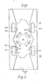
- venturi effect devices used to form the seals 3-and 4 were airmovers made by Brauer and the principle is shown in Fig. 2.
- First and second devices 28 and 29 are mounted back to back so that the combined effect is to produce a dead zone 30 in the centre and common to both airmovers.
- Compressed nitrogen flows from the small inlet 31 into an annular chamber '32.
- the nitrogen is then throttled through the annular gap 33.
- the thin layer of nitrogen 'created then adheres to the profile 34 and flows parallel to the axis of the seal.
- the diameter of the bore of the seal is about 20 mm but could be in the range of 10-75 mm.
- the walls of the seal are referenced 40 and the fibre direction is indicated by the arrows "FIBRE 20".
- the seal works when no optical fibre is present.
- the seal has application in other on-line processes for coating as well as reaction deposition but has particular advantage here where toxic and pyrophoric gases like Silane are used in the process. With such gases it is important that all parts of the system, including the regulators, are airfree before introduction of the gas into the system.
- the regulators on the NO, NH 3 and SiH 4 cylinders are equipped with purge lines. Input gas for this purge is taken from the same N 2 supply as is used for the carrier gas/diluent during actual deposition. After the mixing filter on the vapour train the reactant gas line is taken to a separate manifold at the top of the pulling tower where, by means of a 3-way tap, the gases can either pass through the reactor or be by-passed directly to the extraction system.
- the advantages of the invention are the ability to coat optical fibres on-line with silicon nitride or oxynitride or other materials to provide an hermetic seal on the fibre whilst providing a gas tight seal to the reaction chamber without disturbing and vibrating the fibre, thus minimising the risk of surface flaws in the fibre.
Landscapes
- Chemical & Material Sciences (AREA)
- Life Sciences & Earth Sciences (AREA)
- Geochemistry & Mineralogy (AREA)
- Engineering & Computer Science (AREA)
- Chemical Kinetics & Catalysis (AREA)
- General Chemical & Material Sciences (AREA)
- General Life Sciences & Earth Sciences (AREA)
- Materials Engineering (AREA)
- Organic Chemistry (AREA)
- Chemical Vapour Deposition (AREA)
- Surface Treatment Of Glass Fibres Or Filaments (AREA)
- Glass Compositions (AREA)
- Optical Fibers, Optical Fiber Cores, And Optical Fiber Bundles (AREA)
Priority Applications (1)
| Application Number | Priority Date | Filing Date | Title |
|---|---|---|---|
| AT85303467T ATE44722T1 (de) | 1984-06-01 | 1985-05-17 | Herstellung eines lichtwellenleiters. |
Applications Claiming Priority (2)
| Application Number | Priority Date | Filing Date | Title |
|---|---|---|---|
| GB8414054 | 1984-06-01 | ||
| GB08414054A GB2159812B (en) | 1984-06-01 | 1984-06-01 | Manufacturing optical fibre |
Publications (3)
| Publication Number | Publication Date |
|---|---|
| EP0163457A2 true EP0163457A2 (de) | 1985-12-04 |
| EP0163457A3 EP0163457A3 (en) | 1986-07-30 |
| EP0163457B1 EP0163457B1 (de) | 1989-07-19 |
Family
ID=10561821
Family Applications (1)
| Application Number | Title | Priority Date | Filing Date |
|---|---|---|---|
| EP85303467A Expired EP0163457B1 (de) | 1984-06-01 | 1985-05-17 | Herstellung eines Lichtwellenleiters |
Country Status (8)
| Country | Link |
|---|---|
| US (1) | US4608276A (de) |
| EP (1) | EP0163457B1 (de) |
| JP (1) | JPH0653596B2 (de) |
| AT (1) | ATE44722T1 (de) |
| CA (1) | CA1261632A (de) |
| DE (1) | DE3571601D1 (de) |
| GB (1) | GB2159812B (de) |
| ZA (1) | ZA853942B (de) |
Cited By (6)
| Publication number | Priority date | Publication date | Assignee | Title |
|---|---|---|---|---|
| EP0226651A1 (de) * | 1985-12-19 | 1987-07-01 | Hewlett-Packard Company | Vorrichtung zur chemischen Dampfphasenabscheidung einer Beschichtung auf eine optische Faser |
| US4863760A (en) * | 1987-12-04 | 1989-09-05 | Hewlett-Packard Company | High speed chemical vapor deposition process utilizing a reactor having a fiber coating liquid seal and a gas sea; |
| EP0374926A1 (de) * | 1988-12-21 | 1990-06-27 | Sumitomo Electric Industries, Ltd. | Verfahren zur Herstellung einer Kohlenstoff-beschichteten optischen Faser |
| EP0424012A1 (de) * | 1989-10-19 | 1991-04-24 | AT&T Corp. | Verfahren zur und Vorrichtung für die Beschichtung von optischen Fasern |
| US5147432A (en) * | 1989-10-19 | 1992-09-15 | At&T Bell Laboratories | Methods of and apparatus for coating optical fibers |
| EP1855988A4 (de) * | 2005-03-08 | 2012-06-06 | Cnt Co Ltd | Massenfertigungssystem für kohlenstoffnanoröhren und massenfertigungsverfahren |
Families Citing this family (12)
| Publication number | Priority date | Publication date | Assignee | Title |
|---|---|---|---|---|
| GB2164934B (en) * | 1984-09-29 | 1988-10-05 | Stc Plc | Optical fibres |
| FI74269C (fi) * | 1985-12-17 | 1988-01-11 | Nokia Oy Ab | Foerfarande och anordning foer beklaedning av en optisk fiber med ett primaeroeverdrag. |
| US4792347A (en) * | 1986-09-25 | 1988-12-20 | Corning Glass Works | Method for coating optical waveguide fiber |
| US5199993A (en) * | 1989-10-19 | 1993-04-06 | At&T Bell Laboratories | Methods of and apparatus for coating optical fibers |
| US5242477A (en) * | 1989-10-19 | 1993-09-07 | At&T Bell Laboratories | Apparatus for coating optical fibers |
| JPH0413635U (de) * | 1990-05-23 | 1992-02-04 | ||
| JP2785635B2 (ja) * | 1992-05-26 | 1998-08-13 | 住友電気工業株式会社 | ハーメチックコート光ファイバの製造装置 |
| DE4339077C2 (de) * | 1993-11-16 | 1997-03-06 | Rheydt Kabelwerk Ag | Verfahren zum Ziehen einer optischen Faser und Vorrichtung zu dessen Durchführung |
| DE9317617U1 (de) * | 1993-11-18 | 1994-01-05 | Kabel Rheydt AG, 41238 Mönchengladbach | Vorrichtung zum Beschichten einer optischen Faser |
| US5942020A (en) * | 1996-01-11 | 1999-08-24 | Tensor Machinery Limited | Apparatus for evacuating air from curing area of UV lamps for fiber-like substrates |
| US6767579B1 (en) * | 1998-11-24 | 2004-07-27 | Corning Incorporated | Methods for protecting silica-containing article in optical fiber manufacturing |
| US20030070452A1 (en) * | 2001-10-12 | 2003-04-17 | Alcatel | Process for online spheroidization of quartz and silica particles |
Family Cites Families (4)
| Publication number | Priority date | Publication date | Assignee | Title |
|---|---|---|---|---|
| BE794960A (fr) * | 1972-02-02 | 1973-08-02 | Ici Ltd | Procede de revetement |
| US4402993A (en) * | 1981-03-20 | 1983-09-06 | Gulf & Western Manufacturing Company | Process for coating optical fibers |
| US4526599A (en) * | 1981-08-28 | 1985-07-02 | At&T Bell Laboratories | Optical fiber fabrication process |
| US4518628A (en) * | 1982-05-28 | 1985-05-21 | International Telephone And Telegraph Corporation | Hermetic coating by heterogeneous nucleation thermochemical deposition |
-
1984
- 1984-06-01 GB GB08414054A patent/GB2159812B/en not_active Expired
-
1985
- 1985-05-17 EP EP85303467A patent/EP0163457B1/de not_active Expired
- 1985-05-17 DE DE8585303467T patent/DE3571601D1/de not_active Expired
- 1985-05-17 AT AT85303467T patent/ATE44722T1/de not_active IP Right Cessation
- 1985-05-21 US US06/736,327 patent/US4608276A/en not_active Expired - Lifetime
- 1985-05-23 CA CA000482229A patent/CA1261632A/en not_active Expired
- 1985-05-24 ZA ZA853942A patent/ZA853942B/xx unknown
- 1985-05-31 JP JP60118666A patent/JPH0653596B2/ja not_active Expired - Lifetime
Cited By (7)
| Publication number | Priority date | Publication date | Assignee | Title |
|---|---|---|---|---|
| EP0226651A1 (de) * | 1985-12-19 | 1987-07-01 | Hewlett-Packard Company | Vorrichtung zur chemischen Dampfphasenabscheidung einer Beschichtung auf eine optische Faser |
| US4863760A (en) * | 1987-12-04 | 1989-09-05 | Hewlett-Packard Company | High speed chemical vapor deposition process utilizing a reactor having a fiber coating liquid seal and a gas sea; |
| EP0374926A1 (de) * | 1988-12-21 | 1990-06-27 | Sumitomo Electric Industries, Ltd. | Verfahren zur Herstellung einer Kohlenstoff-beschichteten optischen Faser |
| US5035484A (en) * | 1988-12-21 | 1991-07-30 | Sumitomo Electric Industries, Ltd. | Method and apparatus for producing coated optical fiber |
| EP0424012A1 (de) * | 1989-10-19 | 1991-04-24 | AT&T Corp. | Verfahren zur und Vorrichtung für die Beschichtung von optischen Fasern |
| US5147432A (en) * | 1989-10-19 | 1992-09-15 | At&T Bell Laboratories | Methods of and apparatus for coating optical fibers |
| EP1855988A4 (de) * | 2005-03-08 | 2012-06-06 | Cnt Co Ltd | Massenfertigungssystem für kohlenstoffnanoröhren und massenfertigungsverfahren |
Also Published As
| Publication number | Publication date |
|---|---|
| EP0163457B1 (de) | 1989-07-19 |
| US4608276A (en) | 1986-08-26 |
| JPH0653596B2 (ja) | 1994-07-20 |
| EP0163457A3 (en) | 1986-07-30 |
| ATE44722T1 (de) | 1989-08-15 |
| ZA853942B (en) | 1986-06-25 |
| GB8414054D0 (en) | 1984-07-04 |
| CA1261632A (en) | 1989-09-26 |
| GB2159812A (en) | 1985-12-11 |
| GB2159812B (en) | 1988-02-10 |
| DE3571601D1 (en) | 1989-08-24 |
| JPS60264347A (ja) | 1985-12-27 |
Similar Documents
| Publication | Publication Date | Title |
|---|---|---|
| EP0163457B1 (de) | Herstellung eines Lichtwellenleiters | |
| EP0308143B1 (de) | Hermetisch verschlossene, optische Fasern | |
| US5194714A (en) | Method and device for outside plasma deposition of hydroxyl ion-free silica | |
| US4118211A (en) | Method of maintaining the strength of optical fibers | |
| JPH09172012A (ja) | ケイ素−酸素含有コーティングの成長法 | |
| DE4317905A1 (de) | Reaktor zur Hydrierung von Chlorsilanen | |
| US4575463A (en) | Method of applying hermetic coating on optical fiber | |
| CN113684468B (zh) | 一种石英件保护层及其制备方法 | |
| US5807614A (en) | Method and device for forming an excited gaseous atmosphere lacking electrically charged species used for treating nonmetallic substrates | |
| EP1068157A1 (de) | Wasserdampfplasmabehandlung von glas | |
| JPH0653595B2 (ja) | 石英系フアイバを窒化硼素によりオンラインコ−テイングする方法及び装置 | |
| US4540601A (en) | Aluminum oxide optical fiber coating | |
| EP0371826B1 (de) | Verfahren zur Herstellung einer optischen Faser | |
| CN1113826C (zh) | 在光学纤维拉伸期间将涂层沉积在其上的方法及实施该方法的装置 | |
| US4650693A (en) | Method for producing an aerosol stream | |
| JPH0549614B2 (de) | ||
| CA1241877A (en) | Method for producing a directed aerosol stream | |
| CA1262307A (en) | Aluminum oxide optical fiber coating | |
| JPS6025381B2 (ja) | 光ファイバ被膜用炉 | |
| JP2785745B2 (ja) | Cvd装置 | |
| CA2096872A1 (en) | Apparatus for the production of hermetically coated optical fiber | |
| JPH02167843A (ja) | 光ファイバ素線 | |
| JPH02212340A (ja) | 光ファイバ薄膜被覆装置 | |
| JPH01129972A (ja) | シリコン窒化酸化膜の形成方法 | |
| JPH0549615B2 (de) |
Legal Events
| Date | Code | Title | Description |
|---|---|---|---|
| PUAI | Public reference made under article 153(3) epc to a published international application that has entered the european phase |
Free format text: ORIGINAL CODE: 0009012 |
|
| AK | Designated contracting states |
Designated state(s): AT BE CH DE FR IT LI LU NL SE |
|
| PUAL | Search report despatched |
Free format text: ORIGINAL CODE: 0009013 |
|
| RAP1 | Party data changed (applicant data changed or rights of an application transferred) |
Owner name: STC PLC |
|
| AK | Designated contracting states |
Kind code of ref document: A3 Designated state(s): AT BE CH DE FR IT LI LU NL SE |
|
| RAP1 | Party data changed (applicant data changed or rights of an application transferred) |
Owner name: STC PLC |
|
| 17P | Request for examination filed |
Effective date: 19870202 |
|
| 17Q | First examination report despatched |
Effective date: 19880122 |
|
| GRAA | (expected) grant |
Free format text: ORIGINAL CODE: 0009210 |
|
| AK | Designated contracting states |
Kind code of ref document: B1 Designated state(s): AT BE CH DE FR IT LI LU NL SE |
|
| PG25 | Lapsed in a contracting state [announced via postgrant information from national office to epo] |
Ref country code: SE Effective date: 19890719 Ref country code: LI Effective date: 19890719 Ref country code: IT Free format text: LAPSE BECAUSE OF FAILURE TO SUBMIT A TRANSLATION OF THE DESCRIPTION OR TO PAY THE FEE WITHIN THE PRESCRIBED TIME-LIMIT;WARNING: LAPSES OF ITALIAN PATENTS WITH EFFECTIVE DATE BEFORE 2007 MAY HAVE OCCURRED AT ANY TIME BEFORE 2007. THE CORRECT EFFECTIVE DATE MAY BE DIFFERENT FROM THE ONE RECORDED. Effective date: 19890719 Ref country code: CH Effective date: 19890719 Ref country code: BE Effective date: 19890719 Ref country code: AT Effective date: 19890719 |
|
| REF | Corresponds to: |
Ref document number: 44722 Country of ref document: AT Date of ref document: 19890815 Kind code of ref document: T |
|
| REF | Corresponds to: |
Ref document number: 3571601 Country of ref document: DE Date of ref document: 19890824 |
|
| ET | Fr: translation filed | ||
| REG | Reference to a national code |
Ref country code: CH Ref legal event code: PL |
|
| PLBE | No opposition filed within time limit |
Free format text: ORIGINAL CODE: 0009261 |
|
| STAA | Information on the status of an ep patent application or granted ep patent |
Free format text: STATUS: NO OPPOSITION FILED WITHIN TIME LIMIT |
|
| PG25 | Lapsed in a contracting state [announced via postgrant information from national office to epo] |
Ref country code: LU Free format text: LAPSE BECAUSE OF NON-PAYMENT OF DUE FEES Effective date: 19900531 |
|
| 26N | No opposition filed | ||
| NLT1 | Nl: modifications of names registered in virtue of documents presented to the patent office pursuant to art. 16 a, paragraph 1 |
Owner name: STC LIMITED TE LONDEN, GROOT-BRITTANNIE. |
|
| NLT1 | Nl: modifications of names registered in virtue of documents presented to the patent office pursuant to art. 16 a, paragraph 1 |
Owner name: NORTHERN TELECOM EUROPE LIMITED TE LONDON, GROOT-B |
|
| REG | Reference to a national code |
Ref country code: FR Ref legal event code: TP |
|
| NLT1 | Nl: modifications of names registered in virtue of documents presented to the patent office pursuant to art. 16 a, paragraph 1 |
Owner name: STC LIMITED TE MAIDENHEAD, GROOT-BRITTANNIE. |
|
| NLS | Nl: assignments of ep-patents |
Owner name: NORTHERN TELECOM LIMITED IN MONTREAL, CANADA |
|
| PGFP | Annual fee paid to national office [announced via postgrant information from national office to epo] |
Ref country code: FR Payment date: 20010411 Year of fee payment: 17 |
|
| PGFP | Annual fee paid to national office [announced via postgrant information from national office to epo] |
Ref country code: DE Payment date: 20010423 Year of fee payment: 17 |
|
| PGFP | Annual fee paid to national office [announced via postgrant information from national office to epo] |
Ref country code: NL Payment date: 20010424 Year of fee payment: 17 |
|
| PG25 | Lapsed in a contracting state [announced via postgrant information from national office to epo] |
Ref country code: NL Free format text: LAPSE BECAUSE OF NON-PAYMENT OF DUE FEES Effective date: 20021201 |
|
| PG25 | Lapsed in a contracting state [announced via postgrant information from national office to epo] |
Ref country code: DE Free format text: LAPSE BECAUSE OF NON-PAYMENT OF DUE FEES Effective date: 20021203 |
|
| PG25 | Lapsed in a contracting state [announced via postgrant information from national office to epo] |
Ref country code: FR Free format text: LAPSE BECAUSE OF NON-PAYMENT OF DUE FEES Effective date: 20030131 |
|
| NLV4 | Nl: lapsed or anulled due to non-payment of the annual fee |
Effective date: 20021201 |
|
| REG | Reference to a national code |
Ref country code: FR Ref legal event code: ST |