EP0163817A2 - Support hydraulique pour moteur - Google Patents
Support hydraulique pour moteur Download PDFInfo
- Publication number
- EP0163817A2 EP0163817A2 EP85102674A EP85102674A EP0163817A2 EP 0163817 A2 EP0163817 A2 EP 0163817A2 EP 85102674 A EP85102674 A EP 85102674A EP 85102674 A EP85102674 A EP 85102674A EP 0163817 A2 EP0163817 A2 EP 0163817A2
- Authority
- EP
- European Patent Office
- Prior art keywords
- chamber
- bearing
- volume
- liquid
- abutment
- Prior art date
- Legal status (The legal status is an assumption and is not a legal conclusion. Google has not performed a legal analysis and makes no representation as to the accuracy of the status listed.)
- Granted
Links
Images



Classifications
-
- F—MECHANICAL ENGINEERING; LIGHTING; HEATING; WEAPONS; BLASTING
- F16—ENGINEERING ELEMENTS AND UNITS; GENERAL MEASURES FOR PRODUCING AND MAINTAINING EFFECTIVE FUNCTIONING OF MACHINES OR INSTALLATIONS; THERMAL INSULATION IN GENERAL
- F16F—SPRINGS; SHOCK-ABSORBERS; MEANS FOR DAMPING VIBRATION
- F16F13/00—Units comprising springs of the non-fluid type as well as vibration-dampers, shock-absorbers, or fluid springs
- F16F13/04—Units comprising springs of the non-fluid type as well as vibration-dampers, shock-absorbers, or fluid springs comprising both a plastics spring and a damper, e.g. a friction damper
- F16F13/26—Units comprising springs of the non-fluid type as well as vibration-dampers, shock-absorbers, or fluid springs comprising both a plastics spring and a damper, e.g. a friction damper characterised by adjusting or regulating devices responsive to exterior conditions
-
- F—MECHANICAL ENGINEERING; LIGHTING; HEATING; WEAPONS; BLASTING
- F16—ENGINEERING ELEMENTS AND UNITS; GENERAL MEASURES FOR PRODUCING AND MAINTAINING EFFECTIVE FUNCTIONING OF MACHINES OR INSTALLATIONS; THERMAL INSULATION IN GENERAL
- F16F—SPRINGS; SHOCK-ABSORBERS; MEANS FOR DAMPING VIBRATION
- F16F13/00—Units comprising springs of the non-fluid type as well as vibration-dampers, shock-absorbers, or fluid springs
- F16F13/04—Units comprising springs of the non-fluid type as well as vibration-dampers, shock-absorbers, or fluid springs comprising both a plastics spring and a damper, e.g. a friction damper
- F16F13/06—Units comprising springs of the non-fluid type as well as vibration-dampers, shock-absorbers, or fluid springs comprising both a plastics spring and a damper, e.g. a friction damper the damper being a fluid damper, e.g. the plastics spring not forming a part of the wall of the fluid chamber of the damper
- F16F13/22—Units comprising springs of the non-fluid type as well as vibration-dampers, shock-absorbers, or fluid springs comprising both a plastics spring and a damper, e.g. a friction damper the damper being a fluid damper, e.g. the plastics spring not forming a part of the wall of the fluid chamber of the damper characterised by comprising also a dynamic damper
Definitions
- the invention relates to a hydraulic engine mount according to the preamble of claim 1.
- Such a bearing is known for example from Japanese patent application, application number 55/151699, publication number 57/76340 (A).
- the engine mount described there has a bearing core which is connected to an abutment via a rubber wall.
- Bearing core, rubber wall and abutment enclose a chamber that is filled with liquid.
- a second liquid-filled chamber is connected to this chamber via an opening, the volume of which can be easily changed.
- the two chambers are connected via a thin opening so that the liquid can overflow. Fitted into a widening of the opening is a sliding separating piece that can be pushed back and forth to a limited extent. If this separator comes to its stop, a volume change between the two chambers only takes place through the overflow of liquid. With smaller amplitudes, however, it is not necessary to overflow the liquid, since the separating piece can be pushed back and forth.
- the object of the invention is to determine the causes of these hard impacts and to point out a remedy.
- the main claim describes an engine mount that avoids the disadvantage of the prior art shown.
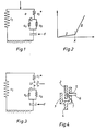
- Fig. 1 the equivalent circuit diagram of a hydraulic engine mount as described in the preamble of claim 1 is described.
- the properties of the bearing are determined by the following variables:
- the dynamic spring stiffness (without the volume stiffness of the supporting body) is expressed by the spring constant c l , which is the spring constant c 1 * connected in parallel, with the help of which the volume stiffness is represented.
- the one-chamber and two-chamber bearings do not differ.
- the second chamber is separated from the first chamber by an element which can be deflected with a relatively low spring force, so that the pressure in the first chamber is increased when force is exerted on the bearing core, as a result of which the element is deflected.
- This spring property which is primarily determined by the spring constant of the deflection element, is designated c b , and as can be seen in a, the deflection is possible up to a stop up or down. However, if this element to be deflected comes to a stop, the spring constant c b is switched ineffectively by the harder spring constant c a . For the appropriate design of the bearing, c a becomes a lot chosen larger c b .
- the overflow opening between the two chambers is represented by the attenuator d.
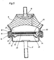
- the spring stiffness c b is effective in area I.
- the amplitude is so large that its height reaches the stop a.
- the spring constant c is thus additionally effective; this area is represented by branch II of the curve. Accordingly, in order to mitigate the impact on the stop, an attempt would have to be made to “round off” the kink in the area x, ie not to change the transition from I to II abruptly, but to make it smooth. Another option would be to make area I somewhat steeper by making area II a little flatter. However, this removes the desired properties of the bearing.
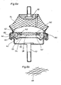
- the equivalent circuit diagram shown in FIG. 3 was used in order to avoid the undesired operating states.
- the area designated LV it is provided that the lower end of the spring c l * can be separated from the springs c a and c b connected in parallel.
- the parallel circuit c a and c b which is responsible for the hard shock in the transition x, remains ineffective , so that the constant spring constant is formed only by the spring c l . No damping is required in these operating states.
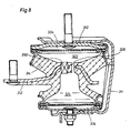
- Fig. 4 shows a basic possibility to provide this connection.
- the member attached to the spring c 1 * is referred to, which is received in a bracket-like bracket 3, from which the parallel connection of the springs c a and c b leads away at 4.
- the bracket-like console 3 has an opening 5 through which a fixing member 6 can be inserted, which in the inserted state rigidly holds the extension 2 in a corresponding recess 7 and rigidly connects the bracket and the corresponding extension 4.
- FIG. 5 shows a first embodiment of a hydraulic bearing.
- the bearing core to which the engine block is fastened is designated by 10.
- the abutment 12 is fastened on the body side, and the bearing located between the bearing core 10 and the abutment 12 has the task of largely absorbing the engine vibrations.
- a relatively strong rubber part 14 is provided, which connects the bearing core 10 to the abutment 12 and at the same time represents part of the inclusion for an upper chamber 22 for the hydraulic bearing.
- the rubber part 14 is connected to the abutment 12 via a wall 16.
- the chamber 22, which is filled with a liquid, for example water, is separated from a second chamber 24 by a wall consisting of two parts 18 and 20.
- a membrane 28 is clamped between these two mutually parallel partial walls 18 and 20 and is mounted in a cavity 36, which is delimited by the two walls 18 and 20, so as to be freely movable to a limited extent.
- the upper wall 18 in FIG. 5 has flow openings 25, the lower part turn 20 has flow openings 26 through which liquid can pass to both sides of the membrane.
- a limited fluid exchange between the chamber 22 and the chamber 24 is made possible either by the porosity of the membrane 28 or by a lateral flow path 36.
- Overflow from the chamber 22 into the chamber 24 means that the lower end wall 34 of the chamber 24 in is changed in shape to increase the volume of the chamber 24.
- a certain throttling takes place due to the overflow of the liquid from the chamber 22 into the chamber 24.
- a bypass 50 is provided which creates a connection between the chambers 22 and 24.
- This bypass 50 is to be opened if the hard bearing properties are undesirable, for example at low speeds, so that when the membrane 28 comes into contact with the wall 20, liquid flows through the bypass 50 from the chamber 22 into the chamber 24.
- the bypass 50 consists of an arbitrarily openable and closable valve, which is closed at higher speeds, so that the bearing becomes soft with small amplitudes and hard with larger amplitudes. At low speeds, however, the valve 50 is opened so that even with larger amplitudes the bearing remains soft and no hard blows occur, so that the relatively low-frequency blows of large amplitude are avoided, for example, when the engine is not running smoothly or when the engine is started.
- FIG. 6a shows a further hydraulic engine mount.
- a bearing core 110 and an abutment 112 are again provided here.
- the bearing core 110 is connected to the abutment 112 via the rubber part 114 and the rigid housing wall 116.
- the housing wall 116 leads to the bearing core 112 via a cup-shaped metal part 132.
- the volume enclosed by rubber part 114, housing wall 116 and cup-shaped part 132 has a flexible rubber wall 134.
- the resilient rubber wall 134 together with the housing wall 116 and the rubber part 114, encloses a liquid-filled volume, which is separated into two chambers 122 and 124 by a membrane 128, which is held at its ends in a rubber area 120.
- the membrane 128 is supported on its outer circumference in the rubber 120 in such a way that it can move relatively freely in a limited area normal to its area, but in the event of larger deflections it comes to rest on projections 140 and 142, so that further deflection is avoided becomes.
- the membrane can be made relatively rigid or stretchable.
- the extensibility of the membrane 128 can be traced back to the fabric structure.
- the membrane consists of a fabric, the threads 126 of which, as can be seen from FIG. 6b, are corrugated in themselves so that they can be stretched. However, it has come to the stretching of the threads 126, which occurs approximately at the same time as the membrane 128 abuts the projections 140 and 142, a further expansion of the membrane is not possible, the membrane 128 thus forms for the chamber 122 at this moment a relatively rigid wall.
- a flow is provided in the rubber 120 surrounding the membrane 128 circumferentially, which connects the chamber 122 to the chamber 124.
- This flow 144 acts as a throttle, so that a liquid exchange between the chambers 122 and 124 is possible with static and low-frequency loads. At higher frequency loads, however, the fluid exchange between the chambers 122 and 124 cannot take place quickly enough, so that the spring properties of the bearing at small amplitudes are determined by the elasticity of the membrane 128, which yields under all pressure on the volume 122, in the downward direction bulges to the abutment 112 and has finally reached its expansion limit, wherein it abuts the stop 142.
- the spring characteristic of the bearing is essentially determined by the volume stiffness of the rubber part 114, so that the bearing becomes relatively hard.
- This rigidity of the bearing is undesirable when the engine is started or running roughly, with very high amplitudes, and a bypass 150 is therefore provided which connects the chamber 122 to the chamber 124, the flow opening being of a sufficient size so that the throttling effect can be neglected.
- a free overflow of liquid from the chamber 122 into the chamber 124 is largely possible, the chamber 124 being able to absorb liquid without further ado due to the flexibility of its lower limit 134.
- This flow or bypass 150 can always be opened when the hard properties of the bearing are not desired, but rather large amplitudes are to be expected, which should not be transmitted to the abutment 112.
- Typical operating conditions for this are the starting of the engine or an uneven running of the engine at or even below the normal speed. In these operating conditions, a valve can be actuated which opens the flow 150 in order to close it again at engine speeds which are somewhat above the idling speed.
- FIG. 7 shows a further embodiment of a hydraulic motor bearing, this bearing also has a bearing core 210 and an abutment 212.
- Bearing core 210 and abutment 212 are connected to one another via a rubber part 214.
- the liquid in this bearing is essentially enclosed by the rubber 214 into which the bearing core 210 is vulcanized, by the approximately annular abutment 212 and by an annular rubber part 234 fastened to the underside of the annular abutment 212, which has a mass 240 in its center wearing.
- the rigid partition 228 has flow openings 226 which, due to their small dimensions, produce a throttling effect when liquid flows over from the chamber 222 into the chamber 230.
- the rigid wall 228 is circumferentially clamped between soft rubber lips 236, so that the partition wall 228 is relatively easy to move in the normal direction to its surface with low amplitudes. With larger amplitudes, however, the wall comes up against a stop 242 made of rubber, so that a further deflection is substantially prevented.
- the mass 240 which is elastically embedded in the wall 234 of the lower chamber 230, serves as a damper mass in order to improve the absorption behavior of the bearing compared to the static rigidity at higher frequencies by oscillating in phase with the vibrations introduced via the bearing core 210.
- this damper principle is not the subject of the present invention and is known.
- a closable opening 250 is provided between the chamber 222 and the chamber 230, which, like in the bearings already described, can be opened at low speeds and closed at high speeds.
- the dimensions of the opening 250 are such that the throttling effect can be neglected, so that a free overflow from the chamber 222 into the chamber 230 is made possible in a first approximation.
- a bearing core 310 is connected to an abutment 312 via a rubber part 314.
- the rubber part 314 encloses a liquid volume approximately like a cylinder jacket, a constriction in the middle separating this volume into two chambers 322 and 324.
- the top of the liquid volume is closed off by a plate connected to the abutment 310, which is forcibly connected to the underside of the lower chamber 324 via a bracket 311, so that a movement of the abutment 310, which leads to a narrowing of the volume 322, at the same time leads to a forced movement of the lower plate in the same direction, which causes an increase in the volume 324.
- a small, non-liquid-filled chamber 334 is provided above and below the liquid volume, so that small amplitudes do not result in a change in the liquid volume.
- An interaction of the abutment 310 with the liquid-filled volume 322 and 324 only occurs at larger amplitudes, so that an overpressure builds up in the chamber 322 and a vacuum in the chamber 324.
- a throttle opening 326 is provided between the two chambers, through which, in the static case or at low frequencies, an overpressure and underpressure can be compensated by a liquid compensation, so that the bearing remains relatively soft here. However, if the flows through the throttle opening 326 become so large that rapid compensation is no longer possible, the throttling effect becomes noticeable and the bearing becomes relatively hard.
- an opening 350 parallel to the throttle 326 can be opened, the width of which enables liquid to overflow essentially without a throttling effect.
- a valve can be provided here which closes the opening 350 again in certain operating states; such a closure is particularly desirable at higher engine speeds.
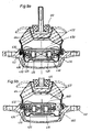
- FIG. 9a and 9b show a further embodiment of a hydraulic engine mount, in which the invention is implemented.
- the vibration is transferred via a bearing core 410 to an approximately cup-shaped abutment 412 via a rubber part 414.
- the bell-shaped rubber part 414 and the cup-shaped abutment 412 enclose a space, the upper part of which rests via a flexible rubber wall 416, for example a bellows is sealed.
- Rubber part 414 and rubber wall 416 comprise the liquid-filled volume, which is divided into two chambers 420 and 422.
- a partition 428 which is rigid in itself but displaceable is provided, which contains a screw-shaped throttle 440 which connects the chamber 420 to the chamber 422 as a connecting opening.
- the rigid wall 420 is suspended in a rubber part 430 in a flexible manner.
- wall 428 can be deflected up and down.
- a projection 432 which is provided on the approximately circular wall radially, abuts the attachment 436 of the soft suspension 430, so that a further deflection of the rigid wall 428 is hardly possible.
- the stop 436 for the projection 432 can be made of rubber so that the deflection of the rigid wall 428 is gradually absorbed.
- passages 450 and 460 are also provided.
- the passage 450 is arranged centrally in the rigid wall 428, while alternatively a passage 460 is provided laterally next to the rigid wall in the non-displaceable components. Both passages are activated in the manner described above.
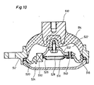
- FIG. 5 Another embodiment of a bearing is described in FIG.
- the bearing core 510 conducts the vibrations via a rubber part 514 to an abutment 512.
- This cup-shaped rubber part 514 forms, together with a lower end 516, a hydraulic volume in which a partition 518 is located.
- the partition wall 518 is connected to the abutment via a rolling bellows 520, while it is connected to the bearing core 514 by a web 532.
- a movement of the bearing core 510 thus leads to a forced movement of the partition 518. Since the partition 518 simultaneously divides the liquid volume into two chambers 522 and 524, the movement of the bearing core 510 increases the volume of one of the two chambers 522 or 524, while the other is scaled down.
- a membrane 528 which can be deflected upwards and downwards.
- this membrane 528 comes to rest against a stop 526 in the event of larger deflections, so that its deflectability is then limited and a further liquid exchange between the chambers 522 and 524 can only take place via a throttle opening 540.
- the liquid exchange in the chambers 522 and 524 can take place only to a very limited extent due to the small throttle opening, so that the bearing itself becomes relatively hard.
- a large opening is provided between the liquid chamber 522 and the liquid chamber 524, which can be provided, for example, at the articulation point of the partition 518 on the rolling bellows 520.
- This opening 550 can optionally be opened and closed, wherein a motor parameter can be used to control the opening or closing.
- the speed is suitable for this, so that the passage 550 is closed above a certain speed threshold, so that the two chambers can only exchange liquid with one another via the throttle 540.
- the passage 550 is opened, so that the throttle 540 is essentially ineffective, since an overflow of the liquid from the chamber 522 into the chamber 524 and vice versa can take place via the passage 550.
- the bearing therefore remains soft even in the case of amplitudes which would lead to a stop of the membrane 528 against its stop spigot 526 in the closed state of the passage 550.
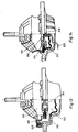
- the dynamic rigidity is also determined by the internal structure of the bearing, because the bearing core 610 is led into the liquid volume via an extension 611.
- a plate 624 is provided which separates the liquid volume into two chambers 620 and 622. Movement of the extension 611 of the bearing core 610 moves the plate 624 up and down in the liquid volume, the chamber 620 being enlarged and the chamber 622 being made smaller or vice versa.
- the plate 624 is mounted between two stops 626 and 628, so that small movements of the extension 611 can be carried out without the plate 624 being carried along, since it has some play between the stops 626 and 628.
- the plate 624 is circular and has a somewhat smaller diameter than the inner diameter of the cup-shaped abutment 612, see above that a small opening 630 remains between the inside of the cup-shaped abutment 612 and the radially outer edge of the plate 624, through which liquid can flow from the chamber 620 into the chamber 622 and vice versa.
- the upper chamber 622 is closed off by an elastic bellows 618, so that when the abutment 610 and the associated extension 611 move upward, the volume of the chamber 620 could expand upwards, but a negative pressure develops in the chamber 622, so that liquid must flow from chamber 620 through throttle 630 into chamber 622.
- a volume 650 is provided which is enclosed at the top and bottom by two rigid plates 654 and 656, while it is delimited on the outside by an elastic rubber part 652.
- This space 650 stored in the chamber 622 which in the example shown is attached to the extension 611, but can also be accommodated in the chamber 622 at any other point, can be controlled via a feed line 658.
- the supply line 658 is used in particular to change the internal pressure of the volume 650, so that with a low internal pressure in the volume 650 when the abutment 610 moves downward, the excess pressure in the chamber 622 can be compensated for by compressing the volume 650 so that the largely incompressible liquid of the chamber 622 does not necessarily have to flow through the throttle 630 into the chamber 620. Conversely, when the abutment 610 moves upward, the negative pressure in the chamber 622 can be compensated for by the volume 650 expanding, so that there is also no need for liquid to flow through the throttle 630.
- volume 650 is either inflated hard with a gaseous medium or filled with a liquid medium, there is a volume compensation inside the chamber 622 through the volume 650 no longer possible or only to a very limited extent, so that a compensation between the liquid chambers 620 and 622 can only take place through the throttle 630.
- the throttle is therefore deactivated by making the volume 650 either compressible or incompressible.
- the fact that the throttle 630 is thereby switched effective or ineffective can be made dependent on the same parameters as in the cases described above.
- a bearing core 710 is provided, which is connected to the abutment 712 via rubber 714.
- a volume of liquid is enclosed in the interior of the bearing, which volume is delimited on the one hand by a rubber wall 713, which is connected to the abutments, and by the rubber 714, which are arranged between the bearing core 710 and the abutment 712.
- a punch 716 connects the rubber 714 to the rubber wall 713 so that both are positively guided together.
- the stamp 716 leads through the opening of a plate 718, which is embedded in the liquid volume and separates the volume into two chambers 720 and 722.
- the plate is supported at its radial ends between two stops 728 and 730, both connected to the abutment 712, with a play 726 being provided.
- Relative movements between the bearing core 710 and the abutment 712 lead to changes in the volume of the chambers 720 and / or the chamber 722, which can be compensated for in the case of small amplitudes by the displacement of the plate 718 within the scope of the play 726.
- liquid can pass from the chamber 720 through a narrow gap into an opening 736 at the edge of the stamp 716, which is also passed through the opening 736.
- this choke 736 "closes" due to higher frequencies, i.e., the sufficient time for the liquid to flow from chamber 720 into chamber 722 or back is no longer available, the bearing becomes very hard.
- this opening is controlled by engine operating parameters such as speed.
- FIG. 13 describes a further embodiment of a bearing which largely corresponds in structure to the other bearings, two chambers 810 and 812 are separated from one another by a deflectable element 814, a bypass 816 is provided between the two chambers, which separates the two chambers 810 and 812 optionally connects with each other.
- a valve 818 is provided in the bypass 816, which in its closed position does not allow liquid to flow from the chamber 810 into the chamber 812 via the bypass 816, but in its open position creates a connection 816 of large diameter between the two chambers 810 and 812.
- the valve 818 is actuated by an electromagnet 820, which is controlled, for example, by the speed of the motor to be supported.
- FIG. 14 A further embodiment is described in FIG. 14, two chambers, namely the chambers 910 and 912, are also provided there, as in FIG. 13, which are kept separate from one another via a deflectable element 914.
- This deflectable element 914 has an embedded membrane 916, one side of which is acted upon by the volume of the first chamber 910, while the other side of this elastic membrane is formed by a volume 918 which is embedded in the deflectable element 914.
- This embedded volume limited on the one hand by the deflectable element 914, on the other hand limited by the membrane 918, can be connected to the outside atmosphere with the aid of a feed line 920, in this case the membrane 916 is relatively elastic and can be deflected by pressure fluctuations in the chamber 910, so that the deflectable element 914 is not influenced by pressure fluctuations in the chamber 910, since the pressure fluctuations to be intercepted by membrane 916. If, however, a negative pressure is applied to the feed line 920 instead of the outside atmosphere, the membrane is in contact with the deflectable element 914 due to the negative pressure in the chamber 918, so that the elasticity of the membrane 916 has no effect. 14 and acts like a conventional two-chamber bearing, that is to say that the leakage differences between the chambers 910 and 912 which occur due to impacts are compensated for by deflecting the displaceable element 914 or by corresponding throttle openings.
Landscapes
- Engineering & Computer Science (AREA)
- General Engineering & Computer Science (AREA)
- Mechanical Engineering (AREA)
- Combined Devices Of Dampers And Springs (AREA)
- Arrangement Or Mounting Of Propulsion Units For Vehicles (AREA)
- Hydraulic Motors (AREA)
- Lubricants (AREA)
- Braking Systems And Boosters (AREA)
- Motor Or Generator Frames (AREA)
- Fluid-Damping Devices (AREA)
- Vehicle Body Suspensions (AREA)
Priority Applications (1)
| Application Number | Priority Date | Filing Date | Title |
|---|---|---|---|
| AT85102674T ATE54020T1 (de) | 1984-06-07 | 1985-03-08 | Hydraulisches motorlager. |
Applications Claiming Priority (2)
| Application Number | Priority Date | Filing Date | Title |
|---|---|---|---|
| DE3421135 | 1984-06-07 | ||
| DE19843421135 DE3421135A1 (de) | 1984-06-07 | 1984-06-07 | Hydraulisches motorlager |
Publications (3)
| Publication Number | Publication Date |
|---|---|
| EP0163817A2 true EP0163817A2 (fr) | 1985-12-11 |
| EP0163817A3 EP0163817A3 (en) | 1988-03-23 |
| EP0163817B1 EP0163817B1 (fr) | 1990-06-20 |
Family
ID=6237780
Family Applications (1)
| Application Number | Title | Priority Date | Filing Date |
|---|---|---|---|
| EP85102674A Expired - Lifetime EP0163817B1 (fr) | 1984-06-07 | 1985-03-08 | Support hydraulique pour moteur |
Country Status (9)
| Country | Link |
|---|---|
| US (1) | US4671227A (fr) |
| EP (1) | EP0163817B1 (fr) |
| JP (1) | JPS612941A (fr) |
| AT (1) | ATE54020T1 (fr) |
| AU (1) | AU577373B2 (fr) |
| CA (1) | CA1233753A (fr) |
| DE (2) | DE3421135A1 (fr) |
| ES (1) | ES8701333A1 (fr) |
| NZ (1) | NZ212282A (fr) |
Cited By (21)
| Publication number | Priority date | Publication date | Assignee | Title |
|---|---|---|---|---|
| EP0216082A1 (fr) * | 1985-09-18 | 1987-04-01 | S.A.G.A. - SOCIETA' APPLICAZIONI GOMMA ANTIVIBRANTI S.p.A. | Support pour la suspension élastique du moteur d'un véhicule automoteur par rapport à son châssis |
| FR2593868A1 (fr) * | 1986-01-30 | 1987-08-07 | Peugeot | Cale hydroelastique a suspension centrale, notamment pour la suspension d'un groupe motopropulseur de vehicule automobile |
| EP0248942A3 (fr) * | 1986-06-11 | 1988-06-08 | Firma Carl Freudenberg | Support de moteur à deux chambres |
| US4767106A (en) * | 1986-02-25 | 1988-08-30 | Automobiles Peugeot | Hydroelastic support, in particular for a vehicle engine |
| US4768760A (en) * | 1986-01-22 | 1988-09-06 | Automobiles Peugeot | Hydro-elastic articulation |
| FR2615260A1 (fr) * | 1987-05-12 | 1988-11-18 | Honda Motor Co Ltd | Dispositif, rempli de fluide, isolant aux vibrations |
| EP0243714A3 (en) * | 1986-04-26 | 1988-11-30 | Lemforder Metallwaren Ag | Two-chamber mount with hydraulic damping, particularly an engine mount in an automotive vehicle |
| US4856750A (en) * | 1987-04-13 | 1989-08-15 | Automobiles Peugeot | Hydroelastic support, in particular for the suspension of a vehicle engine |
| US4871150A (en) * | 1987-01-20 | 1989-10-03 | Automobiles Peugeot | Elastically yieldable support in particular for the suspension of a vehicle engine |
| US4893797A (en) * | 1987-07-07 | 1990-01-16 | Automobiles Peugeot | Hydroelastic support, in particular for the suspension of a motor in a vehicle |
| EP0335007A3 (fr) * | 1988-03-26 | 1990-04-25 | Boge A.G. | Support en caoutchouc à amortissement hydraulique |
| EP0332902A3 (en) * | 1988-03-18 | 1990-05-09 | Metzeler Gesellschaft Mit Beschrankter Haftung | Hydraulically damped dual-chamber engine mount |
| EP0409707A1 (fr) * | 1989-07-19 | 1991-01-23 | Hutchinson | Perfectionnements aux dispositifs antivibratoires hydrauliques |
| EP0436780A1 (fr) * | 1989-12-02 | 1991-07-17 | Firma Carl Freudenberg | Support de moteur à amortissement hydraulique |
| GB2242724A (en) * | 1987-05-12 | 1991-10-09 | Honda Motor Co Ltd | Fluid damped vibroisolating device |
| US5078369A (en) * | 1988-03-08 | 1992-01-07 | Automobiles Peugeot | Elastically yieldable connection with a hydraulic stiffening |
| FR2670262A1 (fr) * | 1990-12-10 | 1992-06-12 | Peugeot | Cale hydroelastique. |
| US5139240A (en) * | 1987-05-12 | 1992-08-18 | Honda Giken Kogyo Kabushiki Kaisha | Fluid-filled vibroisolating device |
| US5209462A (en) * | 1990-12-10 | 1993-05-11 | Automobiles Peugeot | Hydroelastic support |
| GB2278660A (en) * | 1993-05-26 | 1994-12-07 | Honda Motor Co Ltd | Liquid-elastomer vibration-isolating device |
| EP2820321A4 (fr) * | 2012-08-15 | 2016-01-20 | Beijingwest Ind Co Ltd | Appareil de montage |
Families Citing this family (47)
| Publication number | Priority date | Publication date | Assignee | Title |
|---|---|---|---|---|
| JPH0756314B2 (ja) * | 1985-02-27 | 1995-06-14 | 株式会社ブリヂストン | 防振装置 |
| JPH0688514B2 (ja) * | 1986-01-24 | 1994-11-09 | 日産自動車株式会社 | 共振低減クツシヨン |
| DE3614161A1 (de) * | 1986-04-26 | 1987-11-05 | Lemfoerder Metallwaren Ag | Zweikammerstuetzlager mit hydraulischer daempfung, insbesondere motorlager in kraftfahrzeugen |
| JPH0799189B2 (ja) * | 1986-06-12 | 1995-10-25 | 本田技研工業株式会社 | 流体封入型防振装置 |
| DE3639091A1 (de) * | 1986-11-14 | 1988-05-26 | Daimler Benz Ag | Scherelement |
| DE3643556A1 (de) * | 1986-12-19 | 1988-08-18 | Metzeler Gmbh | Hydraulisch daempfendes motorlager |
| JPH0788869B2 (ja) * | 1987-05-12 | 1995-09-27 | 本田技研工業株式会社 | 流体封入防振装置 |
| JPS63185938U (fr) * | 1987-05-25 | 1988-11-29 | ||
| US4783062A (en) * | 1987-07-01 | 1988-11-08 | General Motors Corporation | Electronic hydraulic mount-internal solenoid |
| JPH0718470B2 (ja) * | 1987-07-20 | 1995-03-06 | 日産自動車株式会社 | 制御型防振装置 |
| JPH083343B2 (ja) * | 1987-08-11 | 1996-01-17 | 日産自動車株式会社 | 制御型パワ−ユニットマウント装置 |
| US4789143A (en) * | 1987-09-14 | 1988-12-06 | General Motors Corporation | Electronic motor mount with rotary flow control valve |
| JPH06675Y2 (ja) * | 1987-11-04 | 1994-01-05 | 日産自動車株式会社 | 制御型防振装置 |
| JPH01106651U (fr) * | 1988-01-11 | 1989-07-18 | ||
| DE3801108A1 (de) * | 1988-01-16 | 1989-07-27 | Audi Ag | Hydraulisches motorlager |
| JPH083344B2 (ja) * | 1988-02-29 | 1996-01-17 | 日産自動車株式会社 | 粘度可変流体封入制御型防振体 |
| US4925162A (en) * | 1988-06-17 | 1990-05-15 | Bridgestone Corporation | Vibration isolating devices |
| JPH023518A (ja) * | 1988-06-21 | 1990-01-09 | Nissan Motor Co Ltd | エンジン及びサスペンションの振動制御装置 |
| JPH0756316B2 (ja) * | 1989-07-05 | 1995-06-14 | 日産自動車株式会社 | 粘度可変流体封入制御型防振体 |
| JPH03288039A (ja) * | 1990-04-03 | 1991-12-18 | Toyo Tire & Rubber Co Ltd | 防振装置 |
| US4998592A (en) * | 1990-06-12 | 1991-03-12 | Navistar International Transportation Corp. | Passive mechanical damping system for a truck |
| JPH0450527A (ja) * | 1990-06-18 | 1992-02-19 | Nissan Motor Co Ltd | 車両用エンジン支持装置 |
| JP2621650B2 (ja) * | 1990-11-28 | 1997-06-18 | 日産自動車株式会社 | パワーユニット支持装置 |
| JP2924317B2 (ja) * | 1991-06-18 | 1999-07-26 | 東海ゴム工業株式会社 | 流体封入式マウント装置 |
| JPH05169983A (ja) * | 1991-12-20 | 1993-07-09 | Nissan Motor Co Ltd | パワーユニット支持装置 |
| DE4205229C2 (de) * | 1992-02-21 | 1994-02-24 | Boge Gmbh | Hydraulisch dämpfendes Gummilager |
| FR2690962B1 (fr) * | 1992-05-07 | 1994-08-05 | Peugeot | Support hydroelastique, notamment pour la suspension d'un moteur de vehicule automobile. |
| US6158415A (en) * | 1997-06-02 | 2000-12-12 | Toyota Jidosha Kabushiki Kaisha | Idling speed control device of internal combustion engine and variable vibration isolating support device |
| JP3697565B2 (ja) * | 1998-08-31 | 2005-09-21 | 東洋ゴム工業株式会社 | 液封入式防振装置 |
| US6257562B1 (en) * | 1998-12-11 | 2001-07-10 | Toyo Tire & Rubber Co., Ltd. | Liquid filled vibration isolating device |
| US6089204A (en) * | 1999-09-08 | 2000-07-18 | Caterpillar, Inc. | Combined axial and torsional crankshaft vibration damper for reciprocating engine |
| US6612554B1 (en) | 2001-10-24 | 2003-09-02 | The Goodyear Tire & Rubber Company | Hydraulic antivibration device |
| JP2006144806A (ja) * | 2003-04-04 | 2006-06-08 | Toyo Tire & Rubber Co Ltd | 液封入式防振装置 |
| US20070182076A1 (en) * | 2003-08-06 | 2007-08-09 | Freudenberg-Nok General Partner | Vibration isolator with reflective external travel restrictor and compressive snubber |
| DE10355201B4 (de) * | 2003-11-26 | 2015-07-02 | Bayerische Motoren Werke Aktiengesellschaft | Hydrolager, bei dem der Durchflussquerschnitt eines Strömungskanals durch ein Druckstück mittels magnetorheologischer Flüssigkeit steuerbar ist |
| JP4392667B2 (ja) * | 2005-10-05 | 2010-01-06 | 東海ゴム工業株式会社 | 流体封入式防振装置 |
| JP4959390B2 (ja) * | 2007-03-22 | 2012-06-20 | 東海ゴム工業株式会社 | 流体封入式防振装置 |
| US7552916B1 (en) * | 2007-04-27 | 2009-06-30 | Cadillac Rubber & Plastics, Inc. | Hydraulically damped mounting device |
| US7751963B2 (en) * | 2008-02-14 | 2010-07-06 | Gm Global Technology Operations, Inc. | Self-tuning active engine mount for vehicles with active fuel management engine |
| DE102009034677B4 (de) * | 2009-07-24 | 2013-10-31 | Trelleborg Automotive Germany Gmbh | Dämpfungseinrichtung |
| DE102010030626A1 (de) * | 2010-06-29 | 2011-12-29 | Robert Bosch Gmbh | Pulsationsdämpferelement für eine Fluidpumpe und zugehörige Fluidpumpe |
| FR2970907B1 (fr) * | 2011-01-31 | 2013-07-05 | Peugeot Citroen Automobiles Sa | Cale constitutive d'un dispositif de suspension pour un moteur d'un vehicule automobile. |
| JP2013011315A (ja) * | 2011-06-30 | 2013-01-17 | Tokai Rubber Ind Ltd | 流体封入式防振装置 |
| ES2637789T3 (es) * | 2012-12-14 | 2017-10-17 | Vibracoustic Gmbh | Soporte de motor conmutable |
| US10544851B2 (en) * | 2017-02-23 | 2020-01-28 | Ford Global Technologies, Llc | Vehicular vibration isolation system and apparatus |
| US9889740B1 (en) | 2017-05-26 | 2018-02-13 | Ford Global Technologies, Llc | System and method to control engine mount temperature |
| DE102017112168B4 (de) * | 2017-06-01 | 2021-04-29 | Vibracoustic Gmbh | Trennvorrichtung zum Trennen einer Arbeitskammer und einer Ausgleichskammer eines hydraulisch dämpfenden Lagers sowie ein hydraulisch dämpfendes Lager |
Family Cites Families (20)
| Publication number | Priority date | Publication date | Assignee | Title |
|---|---|---|---|---|
| FR2364373A1 (fr) * | 1976-09-09 | 1978-04-07 | Peugeot | Dispositif de suspension pour machine tournante |
| DE2833776C2 (de) * | 1977-03-23 | 1983-12-15 | Boge Gmbh, 5208 Eitorf | Zweikammer-Motorlager |
| FR2435632A1 (fr) * | 1978-09-06 | 1980-04-04 | Hutchinson Mapa | Perfectionnements apportes aux supports elastiques, notamment pour suspensions de moteurs de vehicules |
| JPS6015806B2 (ja) * | 1980-04-14 | 1985-04-22 | 日産自動車株式会社 | ダンパ付エンジンマウント装置 |
| DE3024089C3 (de) | 1980-06-27 | 1992-10-08 | Boge Gmbh | Hydraulisch dämpfendes lager |
| JPS5943657B2 (ja) * | 1980-07-22 | 1984-10-23 | 日産自動車株式会社 | 自動車用エンジンマウント |
| JPS57138423A (en) * | 1981-02-17 | 1982-08-26 | Nissan Motor Co Ltd | Engine mount device filled with fluid |
| US4483521A (en) * | 1981-07-01 | 1984-11-20 | Nissan Motor Company, Limited | Rubber and fluid type vibration damper |
| DE3140783A1 (de) * | 1981-10-14 | 1983-04-28 | Continental Gummi-Werke Ag, 3000 Hannover | "elastisches lager mit hydraulischer daempfung" |
| DE3214037A1 (de) | 1982-04-16 | 1983-10-20 | Volkswagenwerk Ag, 3180 Wolfsburg | Aggregatlager fuer ein verkehrsmittel, insbesondere fuer ein kraftfahrzeug |
| DE3222204A1 (de) * | 1982-06-12 | 1983-12-15 | Continental Gummi-Werke Ag, 3000 Hannover | Elastisches lager fuer den antriebsmotor in kraftfahrzeugen |
| JPS5988871A (ja) | 1982-11-12 | 1984-05-22 | バ−・ブラウン・コ−ポレ−ション | 高安定低電圧集積回路表面下降状ダイオ−ド構造体及びその製造方法 |
| DE3246205C2 (de) * | 1982-12-14 | 1987-01-08 | Boge Gmbh, 5208 Eitorf | Hydraulisch dämpfendes Gummilager |
| EP0115417B1 (fr) * | 1983-01-25 | 1989-04-19 | Avon Industrial Polymers Limited | Dispositif de montage à amortissement hydraulique |
| JPS59122447U (ja) * | 1983-02-04 | 1984-08-17 | トヨタ自動車株式会社 | 防振ゴム装置 |
| JPS59151637A (ja) * | 1983-02-04 | 1984-08-30 | Toyota Motor Corp | エンジン−トランスミツシヨン組立体の支持構造 |
| GB2137308B (en) * | 1983-03-15 | 1987-12-23 | Mitsubishi Motors Corp | Rolling control apparatus for an engine controlling dampers |
| US4516545A (en) * | 1983-04-15 | 1985-05-14 | Mitsubishi Jidosha Kogyo Kabushiki Kaisha | Apparatus for controlling the rolling of an engine |
| US4583723A (en) * | 1983-06-10 | 1986-04-22 | Toyoda Gosei Co., Ltd. | Elastically damping device for suspension of engine |
| DE3419437A1 (de) * | 1984-05-24 | 1985-11-28 | Metzeler Kautschuk GmbH, 8000 München | Zweikammer-motorlager mit hydraulischer daempfung |
-
1984
- 1984-06-07 DE DE19843421135 patent/DE3421135A1/de active Granted
-
1985
- 1985-03-08 EP EP85102674A patent/EP0163817B1/fr not_active Expired - Lifetime
- 1985-03-08 DE DE8585102674T patent/DE3578348D1/de not_active Expired - Lifetime
- 1985-03-08 AT AT85102674T patent/ATE54020T1/de not_active IP Right Cessation
- 1985-04-23 ES ES542502A patent/ES8701333A1/es not_active Expired
- 1985-05-15 AU AU42495/85A patent/AU577373B2/en not_active Ceased
- 1985-06-04 NZ NZ212282A patent/NZ212282A/en unknown
- 1985-06-05 JP JP60122389A patent/JPS612941A/ja active Pending
- 1985-06-06 CA CA000483318A patent/CA1233753A/fr not_active Expired
- 1985-06-06 US US06/741,862 patent/US4671227A/en not_active Expired - Fee Related
Cited By (31)
| Publication number | Priority date | Publication date | Assignee | Title |
|---|---|---|---|---|
| US4754956A (en) * | 1985-09-18 | 1988-07-05 | S.A.G.A. - Societa' Applicazioni Gomma Antivibranti S.P.A. | Support for the elastic suspension of the engine in a motor-car with respect to the chassis of the same |
| EP0216082A1 (fr) * | 1985-09-18 | 1987-04-01 | S.A.G.A. - SOCIETA' APPLICAZIONI GOMMA ANTIVIBRANTI S.p.A. | Support pour la suspension élastique du moteur d'un véhicule automoteur par rapport à son châssis |
| US4768760A (en) * | 1986-01-22 | 1988-09-06 | Automobiles Peugeot | Hydro-elastic articulation |
| FR2593868A1 (fr) * | 1986-01-30 | 1987-08-07 | Peugeot | Cale hydroelastique a suspension centrale, notamment pour la suspension d'un groupe motopropulseur de vehicule automobile |
| EP0236161A1 (fr) * | 1986-01-30 | 1987-09-09 | Automobiles Peugeot | Cale hydroélastique à suspension centrale, notamment pour la suspension d'un groupe motopropulseur de véhicule automobile |
| US4767107A (en) * | 1986-01-30 | 1988-08-30 | Automobiles Peugeot | Central suspension hydroelastic mount, in particular for the suspension of a motor-vehicle motor-drive unit |
| US4767106A (en) * | 1986-02-25 | 1988-08-30 | Automobiles Peugeot | Hydroelastic support, in particular for a vehicle engine |
| EP0243714A3 (en) * | 1986-04-26 | 1988-11-30 | Lemforder Metallwaren Ag | Two-chamber mount with hydraulic damping, particularly an engine mount in an automotive vehicle |
| EP0248942A3 (fr) * | 1986-06-11 | 1988-06-08 | Firma Carl Freudenberg | Support de moteur à deux chambres |
| US4871150A (en) * | 1987-01-20 | 1989-10-03 | Automobiles Peugeot | Elastically yieldable support in particular for the suspension of a vehicle engine |
| US4856750A (en) * | 1987-04-13 | 1989-08-15 | Automobiles Peugeot | Hydroelastic support, in particular for the suspension of a vehicle engine |
| FR2615260A1 (fr) * | 1987-05-12 | 1988-11-18 | Honda Motor Co Ltd | Dispositif, rempli de fluide, isolant aux vibrations |
| US5139240A (en) * | 1987-05-12 | 1992-08-18 | Honda Giken Kogyo Kabushiki Kaisha | Fluid-filled vibroisolating device |
| GB2242724A (en) * | 1987-05-12 | 1991-10-09 | Honda Motor Co Ltd | Fluid damped vibroisolating device |
| GB2242724B (en) * | 1987-05-12 | 1992-01-22 | Honda Motor Co Ltd | Fluid filled vibroisolating device |
| US4893797A (en) * | 1987-07-07 | 1990-01-16 | Automobiles Peugeot | Hydroelastic support, in particular for the suspension of a motor in a vehicle |
| US5078369A (en) * | 1988-03-08 | 1992-01-07 | Automobiles Peugeot | Elastically yieldable connection with a hydraulic stiffening |
| EP0332902A3 (en) * | 1988-03-18 | 1990-05-09 | Metzeler Gesellschaft Mit Beschrankter Haftung | Hydraulically damped dual-chamber engine mount |
| EP0335007A3 (fr) * | 1988-03-26 | 1990-04-25 | Boge A.G. | Support en caoutchouc à amortissement hydraulique |
| FR2650044A1 (fr) * | 1989-07-19 | 1991-01-25 | Hutchinson | Perfectionnements aux dispositifs antivibratoires hydrauliques |
| EP0409707A1 (fr) * | 1989-07-19 | 1991-01-23 | Hutchinson | Perfectionnements aux dispositifs antivibratoires hydrauliques |
| EP0436780A1 (fr) * | 1989-12-02 | 1991-07-17 | Firma Carl Freudenberg | Support de moteur à amortissement hydraulique |
| US5209462A (en) * | 1990-12-10 | 1993-05-11 | Automobiles Peugeot | Hydroelastic support |
| EP0490718A1 (fr) * | 1990-12-10 | 1992-06-17 | Automobiles Peugeot | Cale hydroélastique |
| FR2670262A1 (fr) * | 1990-12-10 | 1992-06-12 | Peugeot | Cale hydroelastique. |
| US5242158A (en) * | 1990-12-10 | 1993-09-07 | Automobiles Peugeot | Adjustable hydroelastic mounting |
| GB2278660A (en) * | 1993-05-26 | 1994-12-07 | Honda Motor Co Ltd | Liquid-elastomer vibration-isolating device |
| US5443574A (en) * | 1993-05-26 | 1995-08-22 | Honda Giken Kogyo Kabushiki Kaisha | Liquid-sealing type vibration-isolating device |
| GB2278660B (en) * | 1993-05-26 | 1996-11-27 | Honda Motor Co Ltd | Liquid-sealing type vibration-isolating device |
| EP2820321A4 (fr) * | 2012-08-15 | 2016-01-20 | Beijingwest Ind Co Ltd | Appareil de montage |
| US9440524B2 (en) | 2012-08-15 | 2016-09-13 | Beijingwest Industries, Co., Ltd. | Mount apparatus |
Also Published As
| Publication number | Publication date |
|---|---|
| ES542502A0 (es) | 1986-12-01 |
| DE3421135C2 (fr) | 1989-03-09 |
| EP0163817B1 (fr) | 1990-06-20 |
| JPS612941A (ja) | 1986-01-08 |
| ATE54020T1 (de) | 1990-07-15 |
| ES8701333A1 (es) | 1986-12-01 |
| NZ212282A (en) | 1987-07-31 |
| EP0163817A3 (en) | 1988-03-23 |
| US4671227A (en) | 1987-06-09 |
| CA1233753A (fr) | 1988-03-08 |
| DE3421135A1 (de) | 1985-12-12 |
| AU4249585A (en) | 1985-12-12 |
| DE3578348D1 (de) | 1990-07-26 |
| AU577373B2 (en) | 1988-09-22 |
Similar Documents
| Publication | Publication Date | Title |
|---|---|---|
| EP0163817B1 (fr) | Support hydraulique pour moteur | |
| DE3421137C2 (fr) | ||
| DE112012000231B4 (de) | Fluid-gefüllte Schwingungssteuervorrichtung | |
| DE69718236T2 (de) | Flüssigkeitsgefülltes,elastisches Lager mit Öffnungsdurchlässen die so eingestellt sind,dass Empfangs-Schwingungen von jeweiligen verschiedenen Frequenzfeldern gedämpft werden | |
| DE69313474T2 (de) | Hydroelastisches Motorlager | |
| DE68905623T2 (de) | Buchsenartiges hydraulisch gedaempftes motor- oder getriebelager. | |
| DE10037954A1 (de) | Hydrolager | |
| DE4435431B4 (de) | Hydraulisch gedämpfte Anbringungsvorrichtung | |
| DE19603639C2 (de) | Fluidgefüllte elastische Lagerung mit einer Resonanzeinrichtung | |
| DE19816763C1 (de) | Schaltbares, hydraulisch dämpfendes Lager | |
| DE102013011653A1 (de) | Hydraulisch gedämpfte Lagereinrichtung | |
| EP1488132B1 (fr) | Palier de groupes a amortissement hydraulique | |
| EP0415001A1 (fr) | Support hydraulique | |
| DE102015115401B4 (de) | Luftfeder | |
| DE4036538A1 (de) | Aggregatlager | |
| DE69720923T2 (de) | Schwingungsdämpfer mit Masse bewegbar durch Flüssigkeitsdruckänderung in einem Arbeitsraum | |
| EP1249635A2 (fr) | Support hydraulique à deux chambres pour l'amortissement de vibrations | |
| DE19725771C1 (de) | Schaltbares, hydraulisch dämpfendes Lager | |
| EP0257349B1 (fr) | Ressort | |
| EP2456998B1 (fr) | Dispositif amortisseur | |
| DE3903230C2 (fr) | ||
| DE10121399B4 (de) | Hydraulisch gedämpftes Aggregatlager | |
| DE10359457A1 (de) | Hydrolager | |
| DE19812837C2 (de) | Hydraulisch dämpfendes Motorlager | |
| DE3629807A1 (de) | Zweikammerlager |
Legal Events
| Date | Code | Title | Description |
|---|---|---|---|
| PUAI | Public reference made under article 153(3) epc to a published international application that has entered the european phase |
Free format text: ORIGINAL CODE: 0009012 |
|
| 17P | Request for examination filed |
Effective date: 19850321 |
|
| AK | Designated contracting states |
Designated state(s): AT BE CH DE FR GB IT LI LU NL SE |
|
| PUAL | Search report despatched |
Free format text: ORIGINAL CODE: 0009013 |
|
| AK | Designated contracting states |
Kind code of ref document: A3 Designated state(s): AT BE CH DE FR GB IT LI LU NL SE |
|
| 17Q | First examination report despatched |
Effective date: 19890428 |
|
| ITF | It: translation for a ep patent filed | ||
| GRAA | (expected) grant |
Free format text: ORIGINAL CODE: 0009210 |
|
| AK | Designated contracting states |
Kind code of ref document: B1 Designated state(s): AT BE CH DE FR GB IT LI LU NL SE |
|
| REF | Corresponds to: |
Ref document number: 54020 Country of ref document: AT Date of ref document: 19900715 Kind code of ref document: T |
|
| GBT | Gb: translation of ep patent filed (gb section 77(6)(a)/1977) | ||
| REF | Corresponds to: |
Ref document number: 3578348 Country of ref document: DE Date of ref document: 19900726 |
|
| ET | Fr: translation filed | ||
| ITTA | It: last paid annual fee | ||
| PLBE | No opposition filed within time limit |
Free format text: ORIGINAL CODE: 0009261 |
|
| 26N | No opposition filed | ||
| PGFP | Annual fee paid to national office [announced via postgrant information from national office to epo] |
Ref country code: GB Payment date: 19920224 Year of fee payment: 8 |
|
| PGFP | Annual fee paid to national office [announced via postgrant information from national office to epo] |
Ref country code: AT Payment date: 19920227 Year of fee payment: 8 |
|
| PGFP | Annual fee paid to national office [announced via postgrant information from national office to epo] |
Ref country code: BE Payment date: 19920310 Year of fee payment: 8 |
|
| PGFP | Annual fee paid to national office [announced via postgrant information from national office to epo] |
Ref country code: SE Payment date: 19920316 Year of fee payment: 8 Ref country code: LU Payment date: 19920316 Year of fee payment: 8 |
|
| PGFP | Annual fee paid to national office [announced via postgrant information from national office to epo] |
Ref country code: NL Payment date: 19920331 Year of fee payment: 8 |
|
| EPTA | Lu: last paid annual fee | ||
| PG25 | Lapsed in a contracting state [announced via postgrant information from national office to epo] |
Ref country code: LU Free format text: LAPSE BECAUSE OF NON-PAYMENT OF DUE FEES Effective date: 19930308 Ref country code: GB Effective date: 19930308 Ref country code: AT Effective date: 19930308 |
|
| PG25 | Lapsed in a contracting state [announced via postgrant information from national office to epo] |
Ref country code: SE Effective date: 19930309 |
|
| PG25 | Lapsed in a contracting state [announced via postgrant information from national office to epo] |
Ref country code: BE Effective date: 19930331 |
|
| BERE | Be: lapsed |
Owner name: AUDI A.G. Effective date: 19930331 |
|
| PG25 | Lapsed in a contracting state [announced via postgrant information from national office to epo] |
Ref country code: NL Effective date: 19931001 |
|
| GBPC | Gb: european patent ceased through non-payment of renewal fee |
Effective date: 19930308 |
|
| NLV4 | Nl: lapsed or anulled due to non-payment of the annual fee | ||
| EUG | Se: european patent has lapsed |
Ref document number: 85102674.0 Effective date: 19931008 |
|
| PGFP | Annual fee paid to national office [announced via postgrant information from national office to epo] |
Ref country code: FR Payment date: 19950302 Year of fee payment: 11 |
|
| PGFP | Annual fee paid to national office [announced via postgrant information from national office to epo] |
Ref country code: CH Payment date: 19950505 Year of fee payment: 11 |
|
| PGFP | Annual fee paid to national office [announced via postgrant information from national office to epo] |
Ref country code: DE Payment date: 19960329 Year of fee payment: 12 |
|
| PG25 | Lapsed in a contracting state [announced via postgrant information from national office to epo] |
Ref country code: LI Effective date: 19960331 Ref country code: CH Effective date: 19960331 |
|
| REG | Reference to a national code |
Ref country code: CH Ref legal event code: PL |
|
| PG25 | Lapsed in a contracting state [announced via postgrant information from national office to epo] |
Ref country code: FR Effective date: 19961129 |
|
| REG | Reference to a national code |
Ref country code: FR Ref legal event code: ST |
|
| PG25 | Lapsed in a contracting state [announced via postgrant information from national office to epo] |
Ref country code: DE Effective date: 19971202 |