EP0168940A2 - Appareil hydraulique de contrôle pour transmission commandée hydrauliquement et comportant un variateur continu - Google Patents
Appareil hydraulique de contrôle pour transmission commandée hydrauliquement et comportant un variateur continu Download PDFInfo
- Publication number
- EP0168940A2 EP0168940A2 EP85304008A EP85304008A EP0168940A2 EP 0168940 A2 EP0168940 A2 EP 0168940A2 EP 85304008 A EP85304008 A EP 85304008A EP 85304008 A EP85304008 A EP 85304008A EP 0168940 A2 EP0168940 A2 EP 0168940A2
- Authority
- EP
- European Patent Office
- Prior art keywords
- pressure
- transmission
- line pressure
- port
- continuously variable
- Prior art date
- Legal status (The legal status is an assumption and is not a legal conclusion. Google has not performed a legal analysis and makes no representation as to the accuracy of the status listed.)
- Granted
Links
Images





Classifications
-
- F—MECHANICAL ENGINEERING; LIGHTING; HEATING; WEAPONS; BLASTING
- F16—ENGINEERING ELEMENTS AND UNITS; GENERAL MEASURES FOR PRODUCING AND MAINTAINING EFFECTIVE FUNCTIONING OF MACHINES OR INSTALLATIONS; THERMAL INSULATION IN GENERAL
- F16H—GEARING
- F16H47/00—Combinations of mechanical gearing with fluid clutches or fluid gearing
- F16H47/06—Combinations of mechanical gearing with fluid clutches or fluid gearing the fluid gearing being of the hydrokinetic type
- F16H47/065—Combinations of mechanical gearing with fluid clutches or fluid gearing the fluid gearing being of the hydrokinetic type the mechanical gearing comprising gearing of the friction or endless flexible member type
-
- F—MECHANICAL ENGINEERING; LIGHTING; HEATING; WEAPONS; BLASTING
- F16—ENGINEERING ELEMENTS AND UNITS; GENERAL MEASURES FOR PRODUCING AND MAINTAINING EFFECTIVE FUNCTIONING OF MACHINES OR INSTALLATIONS; THERMAL INSULATION IN GENERAL
- F16H—GEARING
- F16H37/00—Combinations of mechanical gearings, not provided for in groups F16H1/00 - F16H35/00
- F16H37/02—Combinations of mechanical gearings, not provided for in groups F16H1/00 - F16H35/00 comprising essentially only toothed or friction gearings
- F16H37/021—Combinations of mechanical gearings, not provided for in groups F16H1/00 - F16H35/00 comprising essentially only toothed or friction gearings toothed gearing combined with continuously variable friction gearing
-
- F—MECHANICAL ENGINEERING; LIGHTING; HEATING; WEAPONS; BLASTING
- F16—ENGINEERING ELEMENTS AND UNITS; GENERAL MEASURES FOR PRODUCING AND MAINTAINING EFFECTIVE FUNCTIONING OF MACHINES OR INSTALLATIONS; THERMAL INSULATION IN GENERAL
- F16H—GEARING
- F16H61/00—Control functions within control units of change-speed- or reversing-gearings for conveying rotary motion ; Control of exclusively fluid gearing, friction gearing, gearings with endless flexible members or other particular types of gearing
- F16H61/66—Control functions within control units of change-speed- or reversing-gearings for conveying rotary motion ; Control of exclusively fluid gearing, friction gearing, gearings with endless flexible members or other particular types of gearing specially adapted for continuously variable gearings
- F16H61/662—Control functions within control units of change-speed- or reversing-gearings for conveying rotary motion ; Control of exclusively fluid gearing, friction gearing, gearings with endless flexible members or other particular types of gearing specially adapted for continuously variable gearings with endless flexible members
- F16H61/66254—Control functions within control units of change-speed- or reversing-gearings for conveying rotary motion ; Control of exclusively fluid gearing, friction gearing, gearings with endless flexible members or other particular types of gearing specially adapted for continuously variable gearings with endless flexible members controlling of shifting being influenced by a signal derived from the engine and the main coupling
Definitions
- the present invention relates to a hydraulic control apparatus for controlling a hydraulically-operated power transmitting system used in an automotive vehicle, having a continuously variable transmission (hereinafter referred to as "CVT").
- CVT continuously variable transmission
- a power transmitting system for a vehicle including a CVT is provided with an auxiliary transmission for changing a direction of drive of the vehicle and for improvement in drivability.
- a power transmitting system is disclosed in Japanese Patent Applications 58-144985 (laid open under Publication No. 60-37455) and 59-12017, which includes a CVT, and an auxiliary or secondary transmission having a frictional coupling device.
- a common hydraulic line pressure is used to operate the CVT and the frictional coupling device of the auxiliary transmission.
- an input torque of the CVT is equal to an output torque of an engine of a vehicle on which the transmitting system is provided.
- This arrangement is advantageous in terms of constructional simplicity or compactness and durability of the CVT.
- an input torque of the auxiliary transmission i.e., a torque acting on the frictional coupling assembly is varied with a speed ratio "r" (N. in /N out where N in and N out represent rotating speeds of input and output shafts, respectively).
- r speed ratio
- the operation of the transmitting system with such a relatively high level of line pressure is disadvantageous in term of durability of the frictional coupling assembly of the auxiliary transmission and the CVT.
- a hydraulic control apparatus for controlling a hydraulically-operated power transmitting system for an automotive vehicle, the transmitting system having a continuously variable transmission and an auxiliary transmission coupled to an output side of the continuously variable transmission, the apparatus comprising: first pressure-generating means for generating a first line pressure used to operate the continuously variable transmission; and second pressure-generating means for generating a second line pressure used to operate a frictional coupling assembly incorporated in the auxiliary transmission.
- the first and second line pressures used respectively for the continuously variable transmission and the frictional. coupling assembly of the auxiliary transmission may be controlled independently of each other by means of a first and a second pressure generator valve, respectively, whereby the level of the first line pressure is adjustable to suit the continuously variable transmission, while the level of the second line pressure is adjustable to meet the auxiliary transmission.
- This arrangement therefore permits increased durability of the power transmitting system, while maintaing a high degree of torque transmission.
- the second pressure-generating means generates the second line pressure, based on an output torque of an engine of the automotive vehicle, and on a speed ratio of the continuously variable transmission.
- the second line pressure may be controlled to an adequate level, as a function of the output torque "Te” and the speed ratio "r", since the input torque of the auxiliary transmission, that is, the torque acting on the frictional coupling-assembly of the auxiliary transmission is changed in relation to the output torque "Te" of the engine as well as to the speed ratio "r” of the CVT.
- control of the second line pressure independently of the first line pressure contributes to restraining shifting shocks upon shifting of the auxiliary transmission while preventing slippage of a transmission belt of the CVT, in the case where the auxiliary transmission has plural forward-drive shift positions for forward driving of the vehicle.
- the plural forward-drive shift positions include a drive position
- the second pressure-generating means comprises: an input port to which the first line pressure is applied while the drive position is selected; an output port form which the second line pressure is generated while the drive position is selected; and a valve spool for controlling a cross sectional area of fluid communication between said input and output ports.
- the valve spool receives a speed-ratio pressure corresponding to the speed ratio of the continuously variable transmission, a feedback pressure corresponding to the second line pressure, . and a throttle pressure corresponding to an angle of opening of a throttle valve of the engine.
- the speed-ratio pressure and the feedback pressure act on the valve spool so as to move the valve spool in one of opposite directions, while the throttle pressure acts on the valve spool so as to move the valve spool in the other direction.
- the continuously variable transmission is of belt-and-pulley type including a first variable-diameter pulley, and a second variable-diameter pulley, a transmission belt connecting the first and second variable-diameter pulleys, and first and second actuators for changing respective effective diameters of the first and second variable-diameter pulleys.
- the first line pressure is applied to one of the first and second actuators for controlling a tension of the transmission belt.
- the CVT 1 includes a pair of input pulley elements 2a, 2b which form a first variable-diameter pulley, a pair of output pulley elements 4a, 4b which form a second variable-diameter pulley, and a transmission belt 6 which connects the input and output pulley elements 2a, 2b and 4a, 4b to transmit power from an engine 7 of an automotive vehicle.
- the input pulley element 2a is disposed on an input shaft 8 such that the element 2a is movable axially of the input shaft 8 but not rotatably relative to the shaft 8.
- the other input pulley element 2b is fixed to the input shaft 8.
- the output pulley element 4a is fixed to an output shaft 10, while the other output pulley element 4b is disposed on the output shaft 10 aixially movably but not rotatably with respect to the shaft 10.
- the input pulley elements 2a, 2b, and the output pulley elements 4a, 4b have opposed surfaces which are tapered such that a distance between the tapered surfaces .increases in a radially outward direction.
- the transmission belt 6 has a trapezoidal cross sectional shape to suit the opposed tapered surfaces of the pully elements 2a, 2b, 4a, 4b.
- An output pulley cylinder or actuator 5 is provided to move the output pulley element 4b, primarily for changing a tension of the belt 6.
- the hydraulic pressure to move the output pulley element 4b relative to the output pulley element 4a is controlled to be as low as possible to the extent that the transmission belt 6 may attain power transmission without slippage on the pulleys.
- an input pulley cylinder or actuator 3 is provided to move the input pulley element 2a, for changing an effective diameter of the first variable-diameter pulley 2a, 2b (a diameter at which the belt 6 engages the pulley).
- a fluid coupling 12 is provided, which has a pump impeller: 16 connected to a crank shaft 14 of the engine 7, and a turbine 18 which is fixed to the input shaft 8 and is rotated by rotation of the pump impeller 16 via a fluid in the coupling 12.
- a direct-coupling lock-up clutch 22 which serves to directly connect the crank shaft 14 to the input shaft 8.
- the direct-coupling lock-up clutch 22 is provided with dampers 24 which absorb or accommodate a shock upon disengagement of the lock-up clutch 22, and a variation in torque of the engine 7.
- Fig. 10 is a schematic diagram showing a general control arrangement for controlling the power transmitting system.
- the CVT 1 includes a pair of input pulley elements 2a, 2b which form a first variable-diameter pulley, a pair of output pulley elements 4a, 4b which form a second variable-diameter pulley, and a transmission belt 6 which connects the input and output pulley elements 2a, 2b and 4a, 4b to transmit power from an engine 7 of an automotive vehicle.
- the input pulley element 2a is disposed on an input shaft 8 such that the element 2a is movable axially of the input shaft 8 but not rotatably relative to the shaft 8.
- the other input pulley element 2b is fixed to the input shaft 8.
- the output pulley element 4a is fixed to an output shaft 10, while the other output pulley element 4b is disposed on the output shaft 10 aixially movably but not rotatably with respect to the shaft 10.
- the input pulley elements 2a, 2b, and the output pulley elements 4a, 4b have opposed surfaces which are tapered such that a distance between the tapered surfaces .increases in a radially outward direction.
- the transmission belt 6 has a trapezoidal cross sectional shape to suit the opposed tapered surfaces of the pully elements 2a, 2b, 4a,' 4b.
- An output pulley cylinder or actuator 5 is provided to move the output pulley element 4b, primarily for changing a tension of the belt 6.
- the hydraulic pressure to move the output pulley element 4b relative to the output pulley element 4a is controlled to be as low as possible to the extent that the transmission belt 6 may attain power transmission without slippage on the pulleys.
- an input pulley cylinder or actuator 3 is provided to move the input pulley element 2a, for changing an effective diameter of the first variable-diameter pulley 2a, 2b (a diameter at which the belt 6 engages the pulley).
- a fluid coupling 12 is provided, which has a pump impeller 16 connected to a crank shaft 14 of the engine 7, and a turbine 18 which is fixed to the input shaft 8 and is rotated by rotation of the pump impeller 16 via a fluid in the coupling 12.
- a direct-coupling lock-up clutch 22 which serves to directly connect the crank shaft 14 to the input shaft 8.
- the direct-coupling lock-up clutch 22 is provided with dampers 24 which absorb or accommodate a shock upon disengagement of the lock-up clutch 22, and a variation in torque of the engine 7.
- the lock-up clutch 22 is engaged so as to prevent loss of power due to transmission by the fluid coupling 12.
- the pump impeller 16 is rotated together with an oil pump 26 (Fig. 3) which delivers a pressurized fluid to the CVT 1, fluid coupling 12, etc., via a hydraulic control device which will be described.
- a counter shaft 28 In parallel with the output shaft 10, there is disposed a counter shaft 28 to which are fixed two gears 30, 32. The engine power from the output shaft 10 of the CVT 1 is transmitted.
- auxiliary transmission 42 is disposed coaxially with the output shaft 10 of the CVT 1.
- This auxiliary transmission 42 includes a complex planetary gear set 43 of RAVIGNEAUX type which includes a first and a second sun gear 44, 46, a first planetary gear 48 meshing with the first sun gear 44, a second planetary gear 50 meshing with the second planetary gear 46, a ring gear meshing with the first planetary gear, and a planet carrier 54 which rotatably supports the first and second planetary gears 48, 50.
- the second sun gear 46 is coupled to a shaft 64 which is integral with the output shaft 10 of the CVT 1 and which serves as an input shaft of the auxiliary transmission 42.
- the carrier 54 is connected to the gear 34.
- a high-range clutch 56 is applied to connect the first sun gear 44 and the shaft 64, while a low-range brake band 58 is applied to hold the first sun gear 44 stationary.
- the ring gear 52 is held stationary by a reverse brake band 60.
- the high-range clutch 56, low-range brake band 58 and reverse brake band 60 are operated by actuators 57, 59 and 61 (Fig. 5), respectively, and these components 56-61 constitute a frictional coupling assembly.
- Fig. 2 shows operating states of the above elements of the frictional coupling assembly build in the auxiliary transmission 42, and speed reduction ratios, in relation with shift positions of the transmission 42.
- marks "o” indicate the engagement or application of the cluch or band 56, 58, 60, while marks “x” indicate their disengagement or release.
- Values pl and p2 are obtained from the following equations:
- a low range in a shift position L (Low) or D (Drive) is established with the first sun gear 44 held stationary by application of the low-range brake band 58.
- the power transmission by the auxiliary transmission 42 is effected at a reduction ratio of (1 + pl/p2).
- a high range in the shift position L or D is established by the engagement of the high-range clutch 56, which causes the planetary gear set 43 to rotate together with the clutch 56.
- the power transmission is effected at a reduction ratio of 1.
- the reverse brake band 60 is applied to hold the ring gear 52 stationary, whereby the power transmission is effected in the reverse direction at a reduction ratio of (1 - 1/p2).
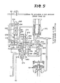
- a hydraulic control arrangement is illustrated in Figs. 3-5, wherein the oil pump 26 sucks up the working fluid through a strainer 72, and delivers the fluid under pressure to a line conduit 74.
- a throttle valve generally indicated at 76 in Fig. 4 generates at its output port 78 a throttle pressure "Pth" which corresponds to an angle 6 of its opening. In other words, the throttle pressure "Pth" corresponds to an output torque of the engine 7.
- the throttle valve 76 has a valve spool 77 which receives an operating pressure a throttle cam 79 that increases with the opening angle 6, and the throttle pressure "Pth" from a control port 81 as a feedback pressure. These operating pressure and the feedback pressure act on the valve spool 77 in the opposite directions.
- the valve spool 77 controls the communication between the line conduit 74 and the output port 78.
- a manual valve 80 having a spool whose axial position is changed according to a selected position of a shift lever which has five shift positions L (Low), D (Drive), N (Neutral), R (Reverse) and P (Parking).
- the manual valve 80 applies a first line pressure PQ1 of the line conduit 74 to a port 83 when the shift position R (Reverse) is selected, and applies the first line pressure Pl1 to a port 85 when the shift position L (Low) is selected.
- the manual valve 80 applies the first line pressure Pl1 to ports 85 and 87.
- a pressure relief valve 89 is provided adjacent to the oil pump 26, to release the working fluid from the line conduit 74 when the first line pressure P£l exceeds a predetermined upper limit.
- a secondary pressure conduit 82 is connected to the line conduit 74 through an orifice 84, and through a port 85 of a primary pressure regulator valve 198 through which an excess of the fluid is drained from the valve 198.
- the secondary pressure conduit 82 is connected through an orifice 88 to a control chamber 90 which is formed in a secondary-pressure regulator valve 86.
- This regulator valve 86 controls the communication between the secondary pressure conduit 82 and a port 94, according to the pressure in the control chamber 90 in relation to a biasing force of a spring 92, so that a secondary pressure Pz in the secondary pressure conduit 82 is maintained at a suitable level.
- the secondary pressure conduit 82 is connected to a lubrication conduit via the port 94 or an orifice 97.
- the previously indicated direct-coupling lock-up clutch 22 incorporated in the fluid coupling 12 in parallel is engaged or disengaged under control of a lock-up control valve 96 which applies the secondary pressure Pz in the secondary pressure conduit 82 selectively to one of opposite sides (engagement side or release side) of the lock-up clutch 22.
- a solenoid valve 100 is provided to control the communication between a control chamber 102 of the lock-up control valve 96 and a drain 104. When the solenoid valve 100 is off (deenergized), the secondary pressure Pz of the secondary pressure conduit 82 is applied to the release side of the lock-up clutch 22, whereby the power from the engine 7 is transmitted to the CVT 1 through the fluid-coupling 12.
- a speed-ratio control valve assembly is indicated generally at 108 in Fig. 4, which includes a first spool valve 110, a second spool valve 112, a first solenoid valve 114, and a second solenoid valve 116. While the first solenoid valve 114 is off, the spool of the first spool valve 110 is moved toward a spring 118 by the secondary pressure Pz in a control chamber 117. In this condition, the first line pressure p tl at a port 119 is applied to a port 122 of the second spool valve 112 via a port 120 of the first spool valve 110, and a port 124 is not in communication with a drain 126.
- the second solenoid valve 114 While the second solenoid valve 114 is on, the spool of the first spool valve 110 is pushed toward the chamber 117 by the spring 118. In this condition, the line pressure is not applied to the port 120, and the port 124 is brought into communication with the drain 126. While the second solenoid valve 116 is off, the spool of the second spool valve 112 is pushed toward a spring 130 by the secondary pressure Pz in a control chamber 128. In this condition, the port 122 is not in communication with a port 132, and a port 134 is in communication with a port 136. The ports 132 and 134 are held in communication with the input pulley actuator 3 of the CVT 1 through a line 138.
- the spool of the second spool valve 112 is moved toward the chamber 128 by the spring 130.
- the ports 122 and 132 communicate with each other while the ports 134 and 136 are not in communication.
- the port 136 is connected with the port 124 through a line 142.
- An orifice 140 is provided in the second spool valve 112 to permit a small flow of the fluid from the port 122 to the port 132 while the second solenoid valve 116 is off.
- the fluid is supplied to the actuator 3 of the CVT 1 at a high rate while the first solenoid valve 114 is off and the second solenoid valve 116 is on, whereby the speed ratio "r" of the CVT 1 is decreased relatively rapidly. While the first and second solenoid valves 114 and 116 are both off, the supply of the fluid to the actuator 3 is accomplished through the orifice 140, and consequently the speed ratio "r" is decreased slowly. While the first and second solenoid valves 114 and 116 are both on, the actuator 3 of the CVT 1 is not supplied with the pressurized fluid, whereby the speed ratio "r" of the CVT 1 is held constant. While the first solenoid valve 114 is on and the second solenoid valve 116 is off, the fluid in the actuator 3 is discharged through the drain 126, and the speed ratio "r" of the CVT 1 is rapidly increased.
- a speed-ratio sensing valve 146 is illustrated in detail in Fig. 6, wherein sleeves 148 and 150 are disposed coaxially within a bore 152, and retained in the axial direction by a retaining ring 154.
- a rod 156 extends through an end portion of the sleeve 148 and is retained by a spring seat 158.
- Another rod 160 is secured at its one end to the rod 156, and is held .at its other end in engagement with the input pulley element 2a so that the element 2a is rotatable relative to the rod 160.
- the rod 160 moves the ' rod 156 in the axial direction by a distance equal to an amount of axial displacement of the input pulley element 2a.
- a spool 162 having lands 164 and 166 is axially slidably fitted in the sleeve 150.
- the spool 162 has a passage 172 which communicates with an annular space between the two lands 164, 166, and with an oil chamber 170.
- the land 166 controls an amount of opening of a port 174 with respect to the annular space 168.
- the port 174 communicates with a drain 176 via an annular space between the outer surface of the sleeve 148 and the inner surface of the bore 152.
- the oil chamber 170 is formed with an output port 170 from which a control pressure Pc is produced.
- the output port 170 communicates with the line conduit 74 via an orifice 180.
- a spring 182 is interposed between the spring seat 158 and the sleeve 150, to bias the rod 156 in a direction away from the sleeve 148.
- a spring 184 is interposed between the spring seat 158 and a flange 186 of the spool 162, in order to bias the spool 162 in a direction toward the oil chamber 170.
- the speed ratio "r" of the CVT 1 is increased as the distance of the movable input pulley element 2a relative to the stationary input pulley element 2b is increased.
- a cut-off valve 190 includes a chamber 194 which communicates with the control chamber 102 of the lock-up control valve 96 via a line 192, and further includes a spool 196 which is moved based on the pressure in the chamber 194 and a biasing force of a spring 195. While the solenoid valve 100 is off, that is, while the lock-up clutch 22 is released (for absorbing a shock of the transmission system when the auxiliary transmission 42 is shifted), the cut-off valve 190 is placed in its closed position to prevent the speed-ratio pressure Pr from being applied to the primary pressure regulator valve 198.
- the primary pressure regulator valve 198 which serves as first pressure-generating means, has: a port 200 to which the throttle pressure Pth is applied; a port 202 to which the speed-ratio pressure Pr is applied; a port 204 connected to the line conduit 74; a port 206 connected to a suction side of the oil pump 26; a port 210 to which the first line pressure Pl1 is applied via an orifice 208; a spool 212 which is axially movable to control the communication between the ports 204 and 206; a spool 214 which receives the throttle pressure Pth and biases the spool 212 toward the port 202; and a spring 216 which biases the spool 212 toward the port 202.
- a sub-primary pressure regulator valve 220 which serves as second pressure-generating means, has: an input port 222 to which is applied the first line pressure Pll from the port 85 of the manual valve 80 while the shift position L or D is selected; an output port 224 from which a second line pressure Pl2 is generated; a port 226 to which the speed-ratio pressure Pr is applied; a port 230 to which is applied through an orifice 228 the second line pressure Pl2 which serves as a feedback pressure; a spool 232 which controls the communication between the input and output ports 222 and 224; a port 234 to which the throttle pressure Pth is applied; a spool 236 which receives the throttle pressure Pth and biases the spool 232 toward the port 226; and a spring 238 which biases the spool 232 toward the port 226.
- this sub-primary pressure regulator valve 220' the following equation is established:
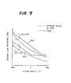
- Fig. 9 indicates a relation between the second line pressure Pl2 generated by the sub-primary pressure regulator valve 220, and its ideal value.
- a shift valve 250 has: a port 252 to which is applied the second line pressure PL2 while the shift position D or L is selected; output ports 254, 256; a port 262 communicating with a drain 260 via an orifice 258; a control port 264 to which is applied the first line pressure Pll from the port 87 of the manual valve 80 when the shift position D is selected; other control ports 266, 268; a drain 270; a spool 272; and a spring 274 biasing the spool 272 toward the port 268.
- the secondary pressure Pz is applied to the control ports 266, 268 via an orifice 276, and the pressure at the control ports 266, 268 is regulated by a solenoid valve 278.
- the two lands of the spool 272 as counted from its bottom have cross sectional areas Sl and S2, respectively.
- the area Sl is smaller than the area S2.
- the solenoid valve 278 is turned on and off in relation to driving parameters of an automotive vehicle. While the solenoid valve 278 is on, the fluid is discharged from a drain 280.
- the input port 252 is in communication with the output port 254, and the output port 256 is in communication with the drain 260 via the port 262 and the orifice 258. Accordingly, the second line pressure P12 is delivered from the output port 254 to an accumulator 282, and to an actuator 57 of the high-range clutch 56, whereby the auxiliary transmission 42 is placed in the high-range position.
- the input and output ports 252, 256 communicate with each other, and the output port 254 is in communication with the drain 270. Consequently, the second line pressure P12 from the output port 256 is delivered to an actuator 59 of the low-range-brake band 58, whereby the auxiliary transmission 42 is placed in the low-range position.
- the first line pressure Pl1 is not applied to the control port 264. Therefore, when the solenoid valve 278 is turned off, the spool 272 is moved toward the spring 274 initially by the secondary pressure Pz acting on the land with the cross sectional area S2, and subsequently by the secondary pressure Pz acting on the land with the cross sectional area Sl.
- the solenoid valve 278 is turned on, the pressure at the control ports 272, 268 is decreased and the spool 272 is moved by the spring 274 toward the port 268. In the shift position L, therefore, the auxiliary transmission 42 may be switched between its high-range and low-range positions according to the on-off states of the solenoid valve 278.
- the first line pressure Pl1 is applied to the control port 264. Consequently, once the spool 272 has been located on the side of the spring 274, the first line pressure Pll from the control port 264 acts on the land with the cross sectional area S2. Subsequently, the spool 272 is held located on the side of the 274, irrespective of the subsequent on-off state of the solenoid valve 272, whereby the auxiliary transmission 42 is held in its high-range postion.
- a shift-timing valve 290 has: a control port 292 communicating with the actuator 57 of the high-range clutch 56; an input port 294 communicating with the output port 256 of the shift valve 250; an output port 296 communicating with the actuator 59. of the low-range brake band 58; a drain 298; a spool 300; and a spring 302 biasing the spool 300 toward the port 292.
- the second line pressure P£2 is delivered from the output port 254 to the actuator 57 of the high-range clutch 56.
- the spool 300 is held on the side of the port 292 by the spring 302, the fluid in the actuator 59 of the low-range brake band 58 is discharged slowly from the drain 260 via the port 262 of the shift valve 250 and the orifice 258.
- the spool 300 is moved against the force of the spring 302 by the pressure at the port 292, whereby the fluid in the actuator 59 of the low-range brake band 58 is discharged rapidly from the drain 298 of the shift-timing valve.
- the release of the low-range brake band 58 is suitably delayed, in order to alleviate a shifting shock of the transmission 42.
- the secondary pressure Pz from the secondary pressure conduit 82 is applied to the solenoid valves 100, 114, 116 and 278, and serve to release the secondary pressure Pz as required.
- the throttle pressure Pth is applied to solenoid valves.
- the biasing force of a spring and the force generated by a solenoid coil must be determined so as to cope with the maximum throttle pressure.
- the solenoid valve must be relatively large-sized, and the response characteristics of a spool of a spool valve associated with the solenoid valve are degraded when the throttle pressure is relatively low. Further, the spring force acting on the spool is difficult to set.
- the secondary pressure Pz is used for the solenoid valves, the above-indicated disadvantages are eliminated, and the freedom of designing of the device is improved.
- Fig. 10 is a schematic block diagram showing a general control arrangement for controlling the power transmitting system which has been described hitherto.
- the control arrangement includes an electronic control device 310 receives input signals indicative of various parameters such as throttle opening angle ⁇ , running speed V of the vehicle, rotating speed Nin at the input side of the CVT 1, temperature Tw of coolant for the engine and selected shift position.
- the electronic control device 310 controls the solenoid valves 100, 114, 116 and 278 through amplifier stage 31-4.
- the ratio of the optimum value of Pl1 in the case of r 2 over that in the case of r 0.5, is 2, while the corresponding ratio of the optimum value of Pl2 is 4.
- the characteristics of variation in the optimum value are different between Pl1 and Pl2.
- the pressure levels Pl1 and Pl2 must be adjusted. as shown in two-dot chain lines in Figs. 7-9.
- a line pressure generated from a single primary pressure regulator valve is commonly used for both the CVT and the auxiliary transmission. If the line pressure is set at a level high enought to cope with the maximum input torque to the auxiliary transmission, the CVT and the -frictional coupling assembly of the auxiliary transmission tend to suffer reduced durability or shortened service life, and the auxiliary transmission tends to be subject to a relatively high shifting shock which gives an adverse effect on the driving comfort of the vehicle.
- the illustrated embodiment of the invention uses the primary pressure regulator valve 198 and the sub-primary pressure regulator valve 220 which provide the first and second line pressures Pl1 and Pl2 that are adjustable to meet the different requirements of the CVT 1 and the auxiliary transmission 42, respectively.
- This arrangement not only assures reliable power transmission by the CVT 1 and the auxiliary transmission 42, but also minimizes reduction in durability of the CVT 1 and the auxiliary transmission 42 and shifting shocks of the transmission 42 upon its,:shiting actions, due to excessive line pressure otherwise used for the power transmitting system.
Landscapes
- Engineering & Computer Science (AREA)
- General Engineering & Computer Science (AREA)
- Mechanical Engineering (AREA)
- Control Of Transmission Device (AREA)
Applications Claiming Priority (2)
| Application Number | Priority Date | Filing Date | Title |
|---|---|---|---|
| JP59123620A JPS612957A (ja) | 1984-06-18 | 1984-06-18 | 無段変速機付き動力伝達装置の油圧制御装置 |
| JP123620/84 | 1984-06-18 |
Publications (3)
| Publication Number | Publication Date |
|---|---|
| EP0168940A2 true EP0168940A2 (fr) | 1986-01-22 |
| EP0168940A3 EP0168940A3 (en) | 1986-03-19 |
| EP0168940B1 EP0168940B1 (fr) | 1988-04-27 |
Family
ID=14865094
Family Applications (1)
| Application Number | Title | Priority Date | Filing Date |
|---|---|---|---|
| EP85304008A Expired EP0168940B1 (fr) | 1984-06-18 | 1985-06-05 | Appareil hydraulique de contrôle pour transmission commandée hydrauliquement et comportant un variateur continu |
Country Status (4)
| Country | Link |
|---|---|
| US (2) | US4751859A (fr) |
| EP (1) | EP0168940B1 (fr) |
| JP (1) | JPS612957A (fr) |
| DE (1) | DE3562418D1 (fr) |
Cited By (1)
| Publication number | Priority date | Publication date | Assignee | Title |
|---|---|---|---|---|
| EP0350200A1 (fr) * | 1988-07-07 | 1990-01-10 | Ford Motor Company Limited | Variateur continu à deux gammes de vitesse |
Families Citing this family (24)
| Publication number | Priority date | Publication date | Assignee | Title |
|---|---|---|---|---|
| JPS5567799A (en) * | 1978-11-16 | 1980-05-22 | Nippon Musical Instruments Mfg | Electronic musical instrument |
| JP2759938B2 (ja) * | 1986-02-04 | 1998-05-28 | トヨタ自動車株式会社 | 車両用変速機の制御方法 |
| JPS63279938A (ja) * | 1987-05-12 | 1988-11-17 | Fuji Heavy Ind Ltd | 無段変速機の油圧制御装置 |
| JPS63297862A (ja) * | 1987-05-28 | 1988-12-05 | Fuji Heavy Ind Ltd | ロックアップトルコン付無段変速機の油圧制御装置 |
| EP0304085B1 (fr) * | 1987-08-21 | 1993-11-10 | Toyota Jidosha Kabushiki Kaisha | Dispositif de commande hydraulique pour une transmission à variation continue de type à courroie et poulies pour un véhicule |
| US5005442A (en) * | 1987-12-11 | 1991-04-09 | Aisin Aw Co., Ltd. | Control system for stepless belt transmissions |
| JP2554698B2 (ja) * | 1988-03-31 | 1996-11-13 | 日産自動車株式会社 | 変速機の油圧制御装置 |
| JP2765081B2 (ja) * | 1989-08-10 | 1998-06-11 | 日産自動車株式会社 | 変速機の油圧制御装置 |
| JPH03125063A (ja) * | 1989-10-09 | 1991-05-28 | Toyota Motor Corp | 車輌用自動変速機の油圧制御装置 |
| BE1004806A3 (nl) * | 1990-11-22 | 1993-02-02 | Volvo Car Sint Truiden Nv | Inrichting voor het regelen van een continu variabele transmissie bij motorvoertuigen. |
| JP2626256B2 (ja) * | 1990-12-28 | 1997-07-02 | トヨタ自動車株式会社 | 車両用ベルト式無段変速機の油圧制御装置 |
| US5988705A (en) * | 1993-05-24 | 1999-11-23 | Pilot Industries, Inc. | Quick connect coupling |
| JPH08285021A (ja) * | 1995-04-10 | 1996-11-01 | Unisia Jecs Corp | 無段変速機の制御装置 |
| US20020137890A1 (en) * | 1997-03-31 | 2002-09-26 | Genentech, Inc. | Secreted and transmembrane polypeptides and nucleic acids encoding the same |
| JP3001858B1 (ja) * | 1998-08-18 | 2000-01-24 | 本田技研工業株式会社 | 潤滑油圧制御装置 |
| JP3429226B2 (ja) * | 1999-07-23 | 2003-07-22 | 本田技研工業株式会社 | 車両用動力伝達装置の制御装置 |
| KR20010019805A (ko) * | 1999-08-31 | 2001-03-15 | 이계안 | 자동차용 무단 변속기의 유압 제어 시스템 |
| US7832297B2 (en) | 2005-04-19 | 2010-11-16 | Hewatt Chris B | Method and apparatus for gyroscopic propulsion |
| US20070144283A1 (en) * | 2005-11-30 | 2007-06-28 | Toshiyuki Hasegawa | Power Transmission Apparatus |
| US8213676B2 (en) | 2006-12-20 | 2012-07-03 | Ge Inspection Technologies Lp | Inspection apparatus method and apparatus comprising motion responsive control |
| US9633426B2 (en) | 2014-05-30 | 2017-04-25 | General Electric Company | Remote visual inspection image capture system and method |
| US8810636B2 (en) | 2006-12-20 | 2014-08-19 | Ge Inspection Technologies, Lp | Inspection apparatus method and apparatus comprising selective frame output |
| US10088025B2 (en) * | 2013-09-24 | 2018-10-02 | Jatco Ltd | Automatic transmission for electric vehicle |
| KR101772830B1 (ko) | 2013-09-25 | 2017-08-29 | 쟈트코 가부시키가이샤 | 토크 캠 장치 및 벨트식 무단 변속 장치 |
Family Cites Families (14)
| Publication number | Priority date | Publication date | Assignee | Title |
|---|---|---|---|---|
| GB2076483B (en) * | 1980-03-24 | 1984-02-01 | Aisin Warner | R vehicles control system for a continuously variable transmission fo |
| US4522086A (en) * | 1981-04-24 | 1985-06-11 | Borg-Warner Corporation | Control system for continuously variable transmission |
| DE3118075C2 (de) * | 1981-05-07 | 1983-02-03 | Audi Nsu Auto Union Ag, 7107 Neckarsulm | Getriebe für Kraftfahrzeuge |
| JPS5812017A (ja) * | 1981-07-14 | 1983-01-24 | Daikin Ind Ltd | 流量・圧力制御装置 |
| JPS5839877A (ja) * | 1981-08-31 | 1983-03-08 | Aisin Warner Ltd | 車両用無段自動変速機の油圧調整装置 |
| FR2522100B1 (fr) * | 1982-02-22 | 1987-04-24 | Valeo | Transmission entre une prise de mouvement et un arbre recepteur, notamment pour vehicule automobile |
| JPS58144985A (ja) * | 1982-02-23 | 1983-08-29 | Kawai Musical Instr Mfg Co Ltd | 磁気カ−ド装置におけるカ−ド操作インジケ−タ |
| JPS591856A (ja) * | 1982-06-28 | 1984-01-07 | Aisin Warner Ltd | 車両用無段自動変速機の制御方法および制御装置 |
| JPS5977157A (ja) * | 1982-10-22 | 1984-05-02 | Nissan Motor Co Ltd | Vベルト式無段変速機の油圧制御装置 |
| US4559850A (en) * | 1982-11-30 | 1985-12-24 | Aisin-Warner, Ltd. | Stepless automatic transmission for motor vehicles |
| JPS59159456A (ja) * | 1983-02-26 | 1984-09-10 | Toyota Motor Corp | ベルト式無段変速機の油圧装置 |
| US4534243A (en) * | 1983-04-26 | 1985-08-13 | Aisin Warner Kabushiki Kaisha | Hydraulic control system for a V-belt transmission |
| JPS6037455A (ja) * | 1983-08-10 | 1985-02-26 | Toyota Motor Corp | 車両用無段変速装置 |
| JPH065095B2 (ja) * | 1984-01-27 | 1994-01-19 | トヨタ自動車株式会社 | 自動車用ベルト式無段変速機の油圧制御装置 |
-
1984
- 1984-06-18 JP JP59123620A patent/JPS612957A/ja active Granted
-
1985
- 1985-05-30 US US06/739,276 patent/US4751859A/en not_active Expired - Lifetime
- 1985-06-05 DE DE8585304008T patent/DE3562418D1/de not_active Expired
- 1985-06-05 EP EP85304008A patent/EP0168940B1/fr not_active Expired
-
1987
- 1987-09-23 US US07/100,266 patent/US4747327A/en not_active Expired - Lifetime
Cited By (1)
| Publication number | Priority date | Publication date | Assignee | Title |
|---|---|---|---|---|
| EP0350200A1 (fr) * | 1988-07-07 | 1990-01-10 | Ford Motor Company Limited | Variateur continu à deux gammes de vitesse |
Also Published As
| Publication number | Publication date |
|---|---|
| DE3562418D1 (en) | 1988-06-01 |
| EP0168940B1 (fr) | 1988-04-27 |
| US4751859A (en) | 1988-06-21 |
| JPS612957A (ja) | 1986-01-08 |
| US4747327A (en) | 1988-05-31 |
| JPH0323783B2 (fr) | 1991-03-29 |
| EP0168940A3 (en) | 1986-03-19 |
Similar Documents
| Publication | Publication Date | Title |
|---|---|---|
| EP0168940B1 (fr) | Appareil hydraulique de contrôle pour transmission commandée hydrauliquement et comportant un variateur continu | |
| US4682518A (en) | Method and apparatus for controlling hydraulically-operated power transmitting system including continuously variable transmission | |
| US4534243A (en) | Hydraulic control system for a V-belt transmission | |
| US4846765A (en) | System for controlling the pressure of oil for a continuously variable transmission | |
| JPS60157554A (ja) | 自動車用ベルト式無段変速機の油圧制御装置 | |
| US5180339A (en) | Double acting secondary sheave servo for a continuously variable transmission | |
| US4685358A (en) | Hydraulic control apparatus for hydraulically-operated power transmitting system having continuously variable transmission | |
| US20060111207A1 (en) | Hydraulic control system for vehicular power transmitting mechanism | |
| US4898050A (en) | System for controlling the pressure of oil for a continuously variable transmission | |
| US5207617A (en) | Hydraulic control apparatus for continuously variable power transmitting system including reversing gear device and auxiliary transmission | |
| EP0520611B1 (fr) | Deuxième poulie servo à double effet pour une transmission à variation continue | |
| US5063815A (en) | Line pressure control for V-belt type continuously variable transmission | |
| EP0615079B1 (fr) | Soupape de contrÔle de sélection des vitesses d'une transmission à variation de vitesse continue | |
| US5291804A (en) | Apparatus for controlling line pressure for automatic transmission upon vehicle starting with the transmission placed in second or higher-gear position | |
| JP2984755B2 (ja) | 無段変速機の変速比制御装置 | |
| JP2626360B2 (ja) | 車両用ベルト式無段変速機の油圧制御装置 | |
| JPS62181928A (ja) | 車両用変速機の制御方法 | |
| JP3116666B2 (ja) | 車両用無段変速機の変速制御装置 | |
| US5458540A (en) | Flow control valve for a continuously variable transmission control system | |
| JPH04285361A (ja) | 車両用ベルト式無段変速機の制御装置 | |
| JP3216286B2 (ja) | 車両用ベルト式無段変速機の油圧制御装置 | |
| GB2142392A (en) | Direct-coupling control system for torque converter in automatic transmission for vehicles | |
| JPH0543895B2 (fr) | ||
| JPS63280957A (ja) | 車両用自動変速機の油圧制御方法 | |
| GB2150656A (en) | Motor vehicle automatic transmissions |
Legal Events
| Date | Code | Title | Description |
|---|---|---|---|
| PUAI | Public reference made under article 153(3) epc to a published international application that has entered the european phase |
Free format text: ORIGINAL CODE: 0009012 |
|
| AK | Designated contracting states |
Designated state(s): DE GB NL |
|
| PUAL | Search report despatched |
Free format text: ORIGINAL CODE: 0009013 |
|
| AK | Designated contracting states |
Kind code of ref document: A3 Designated state(s): DE GB NL |
|
| 17P | Request for examination filed |
Effective date: 19860524 |
|
| 17Q | First examination report despatched |
Effective date: 19861017 |
|
| GRAA | (expected) grant |
Free format text: ORIGINAL CODE: 0009210 |
|
| AK | Designated contracting states |
Kind code of ref document: B1 Designated state(s): DE GB NL |
|
| REF | Corresponds to: |
Ref document number: 3562418 Country of ref document: DE Date of ref document: 19880601 |
|
| PLBE | No opposition filed within time limit |
Free format text: ORIGINAL CODE: 0009261 |
|
| STAA | Information on the status of an ep patent application or granted ep patent |
Free format text: STATUS: NO OPPOSITION FILED WITHIN TIME LIMIT |
|
| 26N | No opposition filed | ||
| REG | Reference to a national code |
Ref country code: GB Ref legal event code: IF02 |
|
| PGFP | Annual fee paid to national office [announced via postgrant information from national office to epo] |
Ref country code: GB Payment date: 20040602 Year of fee payment: 20 |
|
| PGFP | Annual fee paid to national office [announced via postgrant information from national office to epo] |
Ref country code: NL Payment date: 20040603 Year of fee payment: 20 |
|
| PGFP | Annual fee paid to national office [announced via postgrant information from national office to epo] |
Ref country code: DE Payment date: 20040617 Year of fee payment: 20 |
|
| PG25 | Lapsed in a contracting state [announced via postgrant information from national office to epo] |
Ref country code: GB Free format text: LAPSE BECAUSE OF EXPIRATION OF PROTECTION Effective date: 20050604 |
|
| PG25 | Lapsed in a contracting state [announced via postgrant information from national office to epo] |
Ref country code: NL Free format text: LAPSE BECAUSE OF EXPIRATION OF PROTECTION Effective date: 20050605 |
|
| REG | Reference to a national code |
Ref country code: GB Ref legal event code: PE20 |
|
| NLV7 | Nl: ceased due to reaching the maximum lifetime of a patent |
Effective date: 20050605 |