EP0169659A2 - Tongenerator für ein elektroniches Musikinstrument - Google Patents
Tongenerator für ein elektroniches Musikinstrument Download PDFInfo
- Publication number
- EP0169659A2 EP0169659A2 EP85304386A EP85304386A EP0169659A2 EP 0169659 A2 EP0169659 A2 EP 0169659A2 EP 85304386 A EP85304386 A EP 85304386A EP 85304386 A EP85304386 A EP 85304386A EP 0169659 A2 EP0169659 A2 EP 0169659A2
- Authority
- EP
- European Patent Office
- Prior art keywords
- wave form
- form data
- information
- sound generator
- loudness
- Prior art date
- Legal status (The legal status is an assumption and is not a legal conclusion. Google has not performed a legal analysis and makes no representation as to the accuracy of the status listed.)
- Granted
Links
Images


Classifications
-
- G—PHYSICS
- G10—MUSICAL INSTRUMENTS; ACOUSTICS
- G10H—ELECTROPHONIC MUSICAL INSTRUMENTS; INSTRUMENTS IN WHICH THE TONES ARE GENERATED BY ELECTROMECHANICAL MEANS OR ELECTRONIC GENERATORS, OR IN WHICH THE TONES ARE SYNTHESISED FROM A DATA STORE
- G10H7/00—Instruments in which the tones are synthesised from a data store, e.g. computer organs
- G10H7/02—Instruments in which the tones are synthesised from a data store, e.g. computer organs in which amplitudes at successive sample points of a tone waveform are stored in one or more memories
Definitions
- This invention relates to a sound generator to be incorporated in an Electronic Musical Instrument, which is capable of varying the nuance of music sound generated responding to the key depression speed and strength.
- the electronic musical instrument has been remarkably developed in its sound quality and functions thanks to introduction of higher digital technology.
- those electronic musical instruments available in the market, which can afford to generate highly qualified musical sound very close to those issued by natural musical instruments, and which are provided with higher capability, e.g., of automatic performance by means of microcomputer technology.
- the market tends to demand an appearance of those electronic musical instruments having higher capability of music expression ceaselessly.
- the quality and quantity of sound to be generated can be controlled responding to the speed of depression of the key, and the strength of impulse imposed on the key, associated with the initial stage of key depression (hereafter, the latter is to be referred to as the initial touch).
- VCA voltage control amplifier
- the value of detection of the initial touch should be referred to as the touch information.
- the control method by means of conventional initial touch, as mentioned previously, in which VCF and VCA are incorporated, is able to change the timbre and loudness of sound continuously.
- the variation of timbre in this control is simplified too much, on behalf of too much emphasis being placed on continuity of the variation of sound loudness or rimbre, resulting in letting the sound generated be in short of natural tune.
- An object of the present invention is to provide a sound generator for an electronic musical instrument which can satisfy both the natural timbre and continuity of the varying sound quality and loudness of the generated sound simultaneously.
- a part or all of the sounds generated by real musical instrument from their generation to diminition are converted into digital signals, being kept memorized in memories as they are, or as wave form data which are obtained by a certain kind of information condensation process, and one of those complex number of wave form data being selected to be reproduced responding to initial touch information or to the initial touch information and pitch information, or otherwise the amplitude associated with the wave form data reproduction is so arranged as to be modified responding to the initial touch information or the initial touch information and pitch information besides the selective reproduction.
- Fig. 3 is a block diagram of a sound generator for electronic musical instrument in first embodiment of the invention.
- 1 is a ROM for storing combination of wave form data required for musical sound generation
- 3 a musical sound synthesizing means for synthesizing a musical scund according to data which are supplied from ROM 1, a multiplier, 100 a keyboard circuit, and 101 a counter.
- the contents which are memorized in ROM 1 are shown in Fig. 2 as an example.
- a single tone, responding to a key depressed among 48 keys of four octaves is available to be generated.
- key-board circuit 100 will generate a keying signal KON, octave information OCT, note information NOTE and touch information t, where OCT and NOTE are specified as shown in Fig. 1.
- the wave form data combi-- nation is to be taken from such procedures as, loudnesses in music sound of, e.g., piano being actually played and recorded in terms of an eight-level continuum of nuances from ppp (pianississimo: extremely soft) to fff (fortississimo: extremely loud), each of the loudness level being digitized from the generation to the dimension for each of the eight loudness levels.
- the maximum amplitude of each individual loudness level is normalized so as to be the same amplitude throughout the eight levels.
- an optional loudness level can be selected among 256 divided levels, so that the capability of representation of the musical performance can be substancially enhanced. If the loudness level is not controlled in response to the touch information, the continuity of loudness level becomes worse, so the size of memory could not help being expanded because of the necessity of wave form data being to be increased.
- Fig. 6 is a block diagram of a sound generator for electronic musical instrument in the second embodiment of the invention. Some particular explanation is omitted for the part having the same block as given for the example in Fig. 3, alternatively the same numbering being given thereto as that given to the previous example, and key-board circuit 100 and counter 101 being not shown.
- Number (5) is an address generator, which produces address data of ROM 1 from the pitch information, namely, the octave information OCT, note information NOTE and touch information t 5 through t 7 .
- ROM 1 outputs the wave form data combination, taking the address input from the output of address generator 5, supplying it to the musical sound synthesizing means 3.
- the musical sound synthesizing means 3 synthesizes a musical sound wave form from the wave form data provided by ROM 1.
- the output of the musical sound synthesizor 3 is multiplied with touch information t 0 - t 7 by means of the multiplier 4.
- address generator 5 is a ROM which stores the start addresses TAD of a plurality of wave form data combinations stored in ROM 1, 5-20 an adder, 5-30 a counter.
- ROM 5-10 is loaded with additional address inputs, such as octave information OCT, note information NOTE, and touch information t.
- the address generator 5 will generate the address data to be stored in ROM 1 by adding count valve of counter 5-30 with the start address TAD which is read out by ROM 5-10 by the adder 5-20.
- the contents of ROM 5-10 are given in Fi g . 8.
- the start addresses TADs are stored responding to the wave form data combinations corresponding to the sound loudnesses in continuum of 8 levels from ppp to fff.
- the address range of ROM 5-10 has a 9 bit width, being composed of 2 bits of octave information OCT, note information NOTE of 4 bits, and 3 bits of touch information t 5 - t 7' sequentially from the most significant bit downward.
- the wave form data combination to be stored in ROM 1 may be composed in such a way that, e.g., as shown in Fig. 9, a natural musical instrument in played and recorded in each level of loudness from ppp to fff in 8 loudness levels (in the maixmum), the wave form data of 8 combinations (in the maximum) being combined from 8 tones (in the maximum) digitized from the generation to the diminution for each of the original tones, the valve of each amplitude being equalized in each of the maximum loudness level, and finally the required combination being able to be obtained.
- the wave form data combination it is not necessary to prepare any specific circuit as the musical sound sinthesizing means.
- the musical sound synthesizing means 3 should be provided with complication functions of these condensation technology.
- Counter 5-30 and adder 5-20 will generate each address ADR, one step advanced from each of those read out as the start addresses, responding to the reference clock signal CLK.
- Eventually wave form B that is the wave form for mf of D note of the second octave which is shown in Fig. 9, will be read out sequentially from the top responding to CLK from ROM 1.
- the start address read out from ROM 5-10 will also take the same value, as that in the case of keying in mf.
- the degree of timbre variation responding to the status of initial touch will be changeable depending upon pitch of the tone.
- the difference in timbre for each level of loudnesses from ppp to fff is comparatively larger, so that combinations of wave form data having individually different timbre for each of loudness levels, the eight levels of intermediary points from ppp through fff should be prepared.
- Fi g . 10 shows a block diagram of sound generator for electronic musical instrument of the third embodiment of the invention.
- the point different from the example shown in Fig. 6 is the fact that a converter 6 between touch information and loudness information, (hereinafter to be referred to as t/l converter) is provided.
- the touch information is digital representation of the detected valve of keying impulse strength and keying speed, so that it will respond in one to one relationship with the loudness level.
- t/l converter is digital representation of the detected valve of keying impulse strength and keying speed, so that it will respond in one to one relationship with the loudness level.
- the t/l converter 6 converts the touch information t into loudness information l, which is in a linear relationship with the loudness level, incorporating the loudness information (l 0 - l 7 ) alternatively in the place of touch information t (t 0 - t 7 ) which is given in Fig. 6.
- the above feature is given in Fig. 11, in that the mutaul relationship, of performance of keying vs. loudness and timbre of the generated musical tone has come to be determinable optimistically.
- the t/l converter 6 can incorporate ROM or decoder.
- t/l converter 6 regulates the method of conversion responding to the given ocatve information OCT and note information NOTE, associated with conversion of tcuch information t into loudness information l .
- the conversion response characteristics of t/£ converter 6 may be changeable for each octave by means of incorporating both of the ocatve information OCT and touch information t as the address input.
- the musical sound is to be synthesized depending upon digital musical sound synthesizing method in that the musical tones re synthesized by means of interpolation from a plurality of wave forms.
- digital musical sound synthesizing method in that the musical tones re synthesized by means of interpolation from a plurality of wave forms.
- FIG. 13 (a) An acutal example of piano tone wave form is shown in Fig. 13 (a), in that it can be noticed that the leading part which is given identification PCM is involved with substantial variations of wave form so that it is rather difficult to reproduce all of the values of digital samples with high fidelity by means of interpolation, and consequently they could not help being stored into memory as they are, to be read out sequentially in case of the performance.
- the portion where the inscription "interpolation" is given is the part where there are rather comparatively moderato variations of wave forms, which is shown in Fig. 13 (b) as an expanded form. From the expanded figure, it can be noticed that there exists a short of periodicity involved with the wave forms, so that it is feasible to compress the amount of information.
- Fig. 13 (c) Some of the representative wave forms chosen from those shown in Fig. 13 (b) are given on Fig. 13 (c).
- the wave form shown in Fig. 13 (b) can be simulated from the wave forms shown in Fig. 13 (c) with very high accuracy.
- the formula to be used for the interpolation is given below:- where f(i,m,n): Sample of synthesized wave form
- FIG. 14 An example of sound generator system for electronic musical instrument which is based upon the musical sound synthesizing method is shown in Fig. 14, as a configuration block diagram of the fifth embodiment of the invention.
- Fig. 14 1 is a ROM for storing wave form data combinations.
- the wave form data combinations shown in the fifth embodiment are composed of a group of wave forms within the domain of PCM, a group of representative wave forms chosen from those among the interpolation range, and one wave form within the domain of hold area.
- Number 3 stands for a musical sound synthesizing means, for executing, the interpolation computation expressed by equation 1.
- Number 5 refers to an address generator which specifies the address of ROM 1, 9 a timing pulse generator (hereafter referred to as TPG), 7 a conversion ROM which receives touch information t and pitch information OCT and NOTE as address inputs and outputs wave form data combination specifying information a and loudness information £, 4 a multiplier, and 8 an envelope generator.
- TPG timing pulse generator
- OCT and NOTE represent the octave information and note information respectively as in the case shown in Fi g . 3.
- musical tones stretching in a wide range of octaves equivalent to the 88 key- board of piano are obtained. Consequently the octave information OCT is widened to 4 bit range.
- the octave numbers corresponding to the octave information are shown in Fig. 25.
- the contents of conversion ROM 7 for the piano are given in Fig. 15 (in which the numerals are given in hexa decimal digit).
- OCT 4
- the other octaves are devided into one or two groups in terms of notes.
- the wave form data combination for each of plural numbers of divided groups is so prepared as to make the differences between tones hardly to be noticed at the time of simultaneous or continuous playing at different pitches.
- the highest 3 octaves can be represented by the same wave form data, regardless of whichever one of twelve notes contained in these octaves being played, as far as they are played with the same strength.
- TPG 9 An example of configuration of TPG 9 is shownin Fig. 26, where 9-1 is a D-Flip Flop, 9-2 a shift register, 9-3 and 9-4 AND gates, and 9-5 and 9-6 an inverter and a NOR gate.
- the signal timing diagrams in TPG 9 in the configuration shown in Fig. 26 are shown in Figs. 27 (a), (b), (c), (j) and (k).
- the wave form data combination specifying information a and loudness information i are read out.
- the wave form data combination specifying information a which is read out from conversion ROM 7 will be inputted into address generator 5.
- a confi g ura- tion of address generator 5 is shown in Fi g . 17, where the start address ROM 5-1, taking wave form data combination specifying information a as address input, memorizes the start address data TAD in ROM 1 of the wave form data combination which has been specified by a, and outputs the start address data TAD responding to an input.
- the start address ROM 5-1 contents are shown in Fig.
- Selector 5-2 will select the start address data TAD according to INIT signal which prompts the initial setting of musical sound synthesis, feeding it tc Latch 5-3.
- the latch 5-3 will latch the start address data TAD onthe basis of INIT signal, and send it to ABUS.
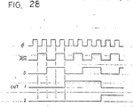
- Counter 5-4 is a binary counter of eleven bit, which executes counting performance with the speed responding to the wave form data read out speed, and which is initialized by INIT signal, letting numeral counting start from the status where all bit is '0'.
- the signal timing of counter 5-4 is shown in Fig. 28. in which CNT3 - CNT9 are eliminated.
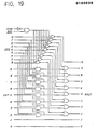
- Masking circuit 5-5 will mask the bit specified among the outputs of counter 5-4. Accordingly, masking circuit 5-5 and counter 5-4 construct a programmable counter.
- FIG. 19 An example of masking circuit 5-5 is shown in Fig. 19, where MSK is the data generated from octave information, by which the mask bits will be specified.
- An example of mask information (MSK) generating circuit. is shown in Fig. 29, and the relationship between octave information OCT and mask information MEK is shown in Fi g . 20.
- CHW is generated by accumulator 3-6, being the signal prompting the replacement of wave form, and being to be '0' exclusively in case of wave form replacement.
- octave No.4 being the center octave, as shown in Fig.
- MSK 4 only is '0', exclusively and the others get '1', so that CNT6 - CNT9 among CNTO - CNT9 in Fig. 19 will be masked, count values, CNTO - CNT5 only being transmitted to BBUS, and CNT6 - CNT9 being to be '0'. Consequently, inspite of counter 5-4 repeating counting performance with 10 bit width, the data on BBUS will be counting value of 6 bit width occurring repeatedly.
- MSK will be decided by octave No. unanimously, because of the fact theat the number of samples N of the representative wave form f (i, n), which is shown in Fig. 13 or expressed by formula (1) is changeable responding to the octave.
- N is chosen as shown in Fig. 20, and MSK is so specified that N is to be counted by means of counter 5-4 and mask circuit 5-5.
- the counter which is to count the required N can be composed by means of the ith bit, i.e., MSK i being set on '0' exclusively, and the others being set on '1'.
- An example of circuit which generates MSK signal is shown in Fig. 29. In this way, BBUS will display repeatedly the-value counting N, and this count value is fed to adder 5-6, where it is added with the start address data TAD which is stored in latch 5-3 shown in Fig.
- the count value on BBUS will be the value resulting from addition of N upon the count value hitherto obtained, being latched eventually by means of latch 5-3 shown in Fig. 17.
- Each of the data consists of 16 bits, in which the upper 12 bits are wave form data W, and the lower 4 bits are control data C.
- the control data C which is stored in * (i, n) is to control how to deal with the two wave form data f (i, n) and f (i-l, n) which are read out simultaneously.
- the control data C is decoded by a decoder included in the accumulator 3-6 shown in Fig. 14, eventually deciding the operation of musical sound synthesizing means 3.
- accumulator 3-6 The configuration of accumulator 3-6 is shown in Fig. 22, in which the decoder 3-62 which is incorporated in the accumulator 3-6 will decode the control data C to generate ⁇ MLP.
- the decoded value ⁇ MLP will be accumulated by adder 3-63 and latch 3-61, eventually to generate and output MLP.
- the MLP revision timing is shown in Fig. 27 (g) .
- the MLP corresponds directly to MLP which is given in formula (1).
- the relationship between the control data C and its decoded value AMLP is shown in Fig. 23.
- the decoder 3-62 incorporated in accumulator 3-6 generate PCM signal exclusively when control data C is 'F'X, and the PCM signal will replace all of the output MLP of accumulator 3-6 by '0' signal.
- Accumulator 3-6 will output CHW signal when the result of accumulation conducted by accumulator 3-6 overflows the ly bits of output MLP.
- CHW incorporates carry-out signal of adder 3-63, and is utilized for wave form revision by means of address generator 5 shown in Fig. 17.
- Address '5400'X which is shown in Fig. 21, is the start address data TAD which is used when the middle C note is played loudly, as evident from Fi g . 15, Fig. 16 and Fig. 18. Consequently, when the middle C note is played loudly latch 503 shown in Fig. 17 will latch '5400'X firstly.
- the address signal timing should refer to Fig. 27(d).
- the read-out two wave form samples will be temporarily stored in latch 3-1 and latch 3-2, which are shown in Fig. 14, respectively, responding to ⁇ 1 and ⁇ 2 .
- the revision timing of wave form data which are temporarily stored in latches 3-1 and 3-2 are given in Fig. 27(e) and (f).
- the output of selector 3-7, MLP will be multiplied by means of multiplier 3-4, and with the other one, f(i, n), (1-MLP) obtained from MLP inverted by inverter 3-8 is multiplied by multiplier 3-3.
- multiplier 3-3 is f(0, n) as MLP, multiplied by all '1', and the output of multiplier 3-4 will be virtually 0 in place of f(l, n), so that adder 3-5 will output substantially the same value to f(0, n).
- Envelope generator 8 generates envelope information ENV which is decaying along with progress of time from the initial value which is taken of the output of ROM 7, i.e. loudness information l.
- the envelope information ENV will be multiplied by output of adder 3-5 at multiplier 4, i.e., the result of calculation f (i, n, n) of interpolation, to finally obtain the synthesized musical sound waveforms.
- multiplier 4 i.e., the result of calculation f (i, n, n) of interpolation
- This compensating operation will effect for wave form data to be reduced on their amplitude diminution to be stored in wave form data combination ROM 1, sc that the number of bits which are used for memory can be improved effectively on their utilization.
- a configuration example of envelope generator 8 is shown in Fig. 24, where selector 8-1 will select loudness information l responding to INIT signal, feeds it as the initial value to latch 8-2 with timing of ⁇ 2 to be stored temporarily, and thereafter reduces it step by step by ⁇ E and eventually outputs it as envelope information.
- ⁇ E is obtained by decoding CCT information and NOTE information.
- the envelope information will be sequentially latched by will be sequentially latched latch 8-2 through selector 8-1.
- KON signal is turned to be 'LOW', letting latch 8-2 be cleared, and letting ENV output be '0'.
- the like envelope generator is disclosed as for its particulars in Japanese laid-open patent application No. 58-200295 'Envelope adding apparatus'.
- a conversion table which is used for determination of wave form data combinations, which are to be incorporated for music synthesis responding to loudness information and touch information, and the generated sound loudness level of the synthesizes wave form. Accordingly, the wave form data combination to be used for synthesis and play back sound loudness level can be specified optionally and independently. That is to say, very natural touch response feeling can be achieved. Further, as an example of the conversion table mentioned above, a configuration is shown in Fig. 15, in which each of loudness is provided with conversion data. In this connection, it is feasible to reduce the size of the conversion table by means of bundling pitch information tion into several groups.
- each of the wave form data combination ROM 1 may be provided with each of the individual wave form data suitable for the tone of the plurality of musical instruments. It will be feasible to emphasize the more appropriate touch response feeling, if conversion ROM 7 is also provided with particular conversion table for each individual musical instrument. It is also allowed to memorize the start address data TAD contained in wave form data combination ROM 1 directly in place of wave form data combination specifying information a alternatively. In this case, the start address ROM 5-1 shown in Fig. 17 can be removed.
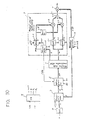
- Fi g . 30 shows a block diagram of the sixth embodiment of the invention, where the difference compared with the embodiment shown in Fig. 14 is the fact that ROM 10 is supplemented.
- the information which has been given as touch information t in the previous examples, is, e.g., the information which is obtained by counting the keying speed in terms of count of open/close operation time of the transfer switches. In the sixth embodiment it should be referred to as keying speed information v.
- ROM 10 receives keying speed information v as address input and reads out touch information t to feed it to ROM 7.
- ROM 10 will convert 7 bit width of keying speed information v into 4 bit width of touch information t.
- keying speed information v is chosen as of 7 bit width, which is, e.g., the information obtained by the method of measuring the time required for transfer switch open/ close operation, which is caused by keying operation, etc.
- the above could not help being called a little bit excessive specification, because the player could not play the tunes with high accuracy deviding into 128 levels as for the range of ppp to fff.
- ROM 10 will convert v of 7 bit width into t of 4 bit width, cutting off the excessive specification.
- bit width of v is prepared as 7 bit-ful, because the value of v will be changeable variously depending upon the construction of key board, method of speed detection and its device.
- ROM 10 functions at the same time for the touch information not to be effected by variation of detected value v of the keying speed, involved with difference of key board construction or keying speed detecting device.
- ROM 10 when the key board construction is revised, if ROM 10 is revised exclusively, it is feasible to maintain almost same status of mutual relationship between the keying speed, and both of loudness and timbre of the generated tone before and after the key board revision. Consequently it is required for the bit width of v to be much wider than that of t.
- the revision of key board construction or keying speed detecting device can be responded exclusively by merely revising the contents of conversion ROM, because of the fact that the conversion ROM is provided for this embodiment, width can convert the keying speed information which is changeable in a wide range by means of the variations of key board construction or keying speed detecting method or device into touch information which is invariable regardless of any key board construction or keying speed detecting device given.
- the method of conversion of keying speed information v into touch information t is often to be referred to as v/t converter.
- Fig. 30 is a v/t converter block diagram which is to be incorporated inthe seventh embodiment of the invention, where v and t are the keying speed information and touch information respectively as same as those given in the embodiment in Fig. 30.
- the point of difference between the seventh embodiment and that shown in Fi g . 30 is nothing but ROM 10 shown in Fig. 30 being replaced by the v/t converter which is shown in Fi g . 31 (a) or (b), so that the other parts of illustration or explanation will be omitted.
- the player's self selection of touch response may be available by means of the above configuration incorporated.
- a microprocess may be used to execute the arithmetic operation to obtain the value of conversion.
- the conversion characteristics shown in Fig. 10 will be simulated by a number of line segments, a linear equation being solved on each of the line segments to get the result, or the incline of each line segment is represented by a value of increment, the conversion value being obtained by accumulation of each of the increments.
- ROMs are used as a plurality of configuration element. However, these ROMs are, obviously, able to be disposed in the different zones of the same package.
Landscapes
- Engineering & Computer Science (AREA)
- General Engineering & Computer Science (AREA)
- Physics & Mathematics (AREA)
- Acoustics & Sound (AREA)
- Multimedia (AREA)
- Electrophonic Musical Instruments (AREA)
Applications Claiming Priority (2)
| Application Number | Priority Date | Filing Date | Title |
|---|---|---|---|
| JP59127062A JPS616689A (ja) | 1984-06-20 | 1984-06-20 | 電子楽器 |
| JP127062/84 | 1984-06-20 |
Publications (3)
| Publication Number | Publication Date |
|---|---|
| EP0169659A2 true EP0169659A2 (de) | 1986-01-29 |
| EP0169659A3 EP0169659A3 (en) | 1988-07-13 |
| EP0169659B1 EP0169659B1 (de) | 1992-02-05 |
Family
ID=14950642
Family Applications (1)
| Application Number | Title | Priority Date | Filing Date |
|---|---|---|---|
| EP85304386A Expired - Lifetime EP0169659B1 (de) | 1984-06-20 | 1985-06-19 | Tongenerator für ein elektroniches Musikinstrument |
Country Status (5)
| Country | Link |
|---|---|
| US (1) | US4681007A (de) |
| EP (1) | EP0169659B1 (de) |
| JP (1) | JPS616689A (de) |
| KR (1) | KR900007892B1 (de) |
| DE (1) | DE3585342D1 (de) |
Cited By (4)
| Publication number | Priority date | Publication date | Assignee | Title |
|---|---|---|---|---|
| FR2610441A1 (fr) * | 1987-02-04 | 1988-08-05 | Deforeit Christian | Procede de synthese sonore par lectures successives de paquets d'echantillons numeriques et instrument de musique electronique pour la mise en oeuvre dudit procede |
| WO1990003640A1 (en) * | 1988-09-30 | 1990-04-05 | Rose Floyd D | Digital musical synthesizer for simulating close-spaced excitations |
| EP0385444A3 (de) * | 1989-03-02 | 1991-02-13 | Yamaha Corporation | Vorrichtung zum Erzeugen eines Musiktonsignals |
| EP0452347A4 (en) * | 1989-01-03 | 1993-03-10 | Hotz Instruments Technology, Inc. | Universal electronic musical instrument |
Families Citing this family (9)
| Publication number | Priority date | Publication date | Assignee | Title |
|---|---|---|---|---|
| JPS6145298A (ja) * | 1984-08-09 | 1986-03-05 | カシオ計算機株式会社 | 電子楽器 |
| JPH0772829B2 (ja) * | 1986-02-28 | 1995-08-02 | ヤマハ株式会社 | 電子楽器におけるパラメ−タ供給装置 |
| US4972753A (en) * | 1987-12-21 | 1990-11-27 | Yamaha Corporation | Electronic musical instrument |
| US5306865A (en) * | 1989-12-18 | 1994-04-26 | Meta-C Corp. | Electronic keyboard musical instrument or tone generator employing Modified Eastern Music Tru-Scale Octave Transformation to avoid overtone collisions |
| US5241124A (en) * | 1990-04-18 | 1993-08-31 | Yamaha Corporation | Electronic musical instrument capable of controlling touch response based on a reference value |
| TW333644B (en) * | 1995-10-30 | 1998-06-11 | Victor Company Of Japan | The method for recording musical data and its reproducing apparatus |
| EP1340219A4 (de) * | 2000-12-05 | 2005-04-13 | Amusetec Co Ltd | Verfahren zum analysieren von musik unter verwendung von klängen von instrumenten |
| JP3879545B2 (ja) * | 2002-03-12 | 2007-02-14 | ヤマハ株式会社 | 楽曲再生制御装置、楽曲再生制御プログラムおよび記録媒体 |
| JP2007011217A (ja) * | 2005-07-04 | 2007-01-18 | Yamaha Corp | 楽音合成装置及びプログラム |
Family Cites Families (12)
| Publication number | Priority date | Publication date | Assignee | Title |
|---|---|---|---|---|
| NL7210530A (de) * | 1971-07-31 | 1973-02-02 | ||
| JPS52121313A (en) * | 1976-04-06 | 1977-10-12 | Nippon Gakki Seizo Kk | Electronic musical instrument |
| JPS534418A (en) * | 1976-07-02 | 1978-01-17 | Hitachi Ltd | Pick up unit |
| JPS604994B2 (ja) * | 1977-09-05 | 1985-02-07 | ヤマハ株式会社 | 電子楽器 |
| US4493781A (en) * | 1981-04-06 | 1985-01-15 | S. C. Johnson & Son, Inc. | Powdered cleansing composition |
| US4411185A (en) * | 1982-04-02 | 1983-10-25 | Kawai Musical Instrument Mfg. Co., Ltd | Touch responsive keyboard electronic musical instrument |
| JPS599698A (ja) * | 1982-07-08 | 1984-01-19 | ヤマハ株式会社 | 自動リズム演奏装置 |
| JPS5950498A (ja) * | 1982-09-16 | 1984-03-23 | ヤマハ株式会社 | 電子楽器 |
| JPS5983199A (ja) * | 1982-11-02 | 1984-05-14 | ヤマハ株式会社 | 電子楽器 |
| JPS5997195A (ja) * | 1982-11-26 | 1984-06-04 | ヤマハ株式会社 | 電子楽器 |
| JPS603892A (ja) * | 1983-06-20 | 1985-01-10 | 松下電器産業株式会社 | 誘導加熱調理器 |
| US4558623A (en) * | 1984-02-07 | 1985-12-17 | Kimball International, Inc. | Velocity and aftertouch sensitive keyboard |
-
1984
- 1984-06-20 JP JP59127062A patent/JPS616689A/ja active Granted
-
1985
- 1985-06-18 US US06/746,119 patent/US4681007A/en not_active Expired - Lifetime
- 1985-06-19 EP EP85304386A patent/EP0169659B1/de not_active Expired - Lifetime
- 1985-06-19 DE DE8585304386T patent/DE3585342D1/de not_active Expired - Lifetime
- 1985-06-20 KR KR1019850004390A patent/KR900007892B1/ko not_active Expired
Cited By (6)
| Publication number | Priority date | Publication date | Assignee | Title |
|---|---|---|---|---|
| FR2610441A1 (fr) * | 1987-02-04 | 1988-08-05 | Deforeit Christian | Procede de synthese sonore par lectures successives de paquets d'echantillons numeriques et instrument de musique electronique pour la mise en oeuvre dudit procede |
| WO1990003640A1 (en) * | 1988-09-30 | 1990-04-05 | Rose Floyd D | Digital musical synthesizer for simulating close-spaced excitations |
| US4998960A (en) * | 1988-09-30 | 1991-03-12 | Floyd Rose | Music synthesizer |
| EP0452347A4 (en) * | 1989-01-03 | 1993-03-10 | Hotz Instruments Technology, Inc. | Universal electronic musical instrument |
| EP0385444A3 (de) * | 1989-03-02 | 1991-02-13 | Yamaha Corporation | Vorrichtung zum Erzeugen eines Musiktonsignals |
| US5140886A (en) * | 1989-03-02 | 1992-08-25 | Yamaha Corporation | Musical tone signal generating apparatus having waveform memory with multiparameter addressing system |
Also Published As
| Publication number | Publication date |
|---|---|
| DE3585342D1 (de) | 1992-03-26 |
| KR860000623A (ko) | 1986-01-29 |
| KR900007892B1 (ko) | 1990-10-22 |
| JPH0413717B2 (de) | 1992-03-10 |
| EP0169659B1 (de) | 1992-02-05 |
| EP0169659A3 (en) | 1988-07-13 |
| JPS616689A (ja) | 1986-01-13 |
| US4681007A (en) | 1987-07-21 |
Similar Documents
| Publication | Publication Date | Title |
|---|---|---|
| US4213366A (en) | Electronic musical instrument of wave memory reading type | |
| HK88289A (en) | Tone information processing device for an electronic musical instrument | |
| EP0169659B1 (de) | Tongenerator für ein elektroniches Musikinstrument | |
| USRE30736E (en) | Tone wave generator in electronic musical instrument | |
| US4327622A (en) | Electronic musical instrument realizing automatic performance by memorized progression | |
| JP2571911B2 (ja) | 楽音信号発生装置 | |
| JPH0772829B2 (ja) | 電子楽器におけるパラメ−タ供給装置 | |
| US5612501A (en) | Automatic accompaniment information producing apparatus | |
| US4114497A (en) | Electronic musical instrument having a coupler effect | |
| JP2921376B2 (ja) | 楽音発生装置 | |
| EP0167847B1 (de) | Tonsignalerzeugungsvorrichtung | |
| JP2605916B2 (ja) | 波形信号発生装置 | |
| US4562763A (en) | Waveform information generating system | |
| JPS619693A (ja) | 楽音発生装置 | |
| US4794837A (en) | Tone signal generator with code converter for converting stored waveshapes of different coding forms into a common coding form | |
| JP2559209B2 (ja) | 楽音信号発生装置 | |
| JP2915452B2 (ja) | 楽音発生装置 | |
| US4612839A (en) | Waveform data generating system | |
| JP3334165B2 (ja) | 楽音合成装置 | |
| JP3087744B2 (ja) | 楽音発生装置 | |
| JPS61248096A (ja) | 電子楽器 | |
| JPH0525116B2 (de) | ||
| JPH039476B2 (de) | ||
| JP3674154B2 (ja) | 楽音合成装置 | |
| JPS595911B2 (ja) | 電子楽器 |
Legal Events
| Date | Code | Title | Description |
|---|---|---|---|
| PUAI | Public reference made under article 153(3) epc to a published international application that has entered the european phase |
Free format text: ORIGINAL CODE: 0009012 |
|
| AK | Designated contracting states |
Designated state(s): DE FR GB IT SE |
|
| PUAL | Search report despatched |
Free format text: ORIGINAL CODE: 0009013 |
|
| AK | Designated contracting states |
Kind code of ref document: A3 Designated state(s): DE FR GB IT SE |
|
| 17P | Request for examination filed |
Effective date: 19890104 |
|
| 17Q | First examination report despatched |
Effective date: 19901122 |
|
| GRAA | (expected) grant |
Free format text: ORIGINAL CODE: 0009210 |
|
| AK | Designated contracting states |
Kind code of ref document: B1 Designated state(s): DE FR GB IT SE |
|
| ITF | It: translation for a ep patent filed | ||
| REF | Corresponds to: |
Ref document number: 3585342 Country of ref document: DE Date of ref document: 19920326 |
|
| ET | Fr: translation filed | ||
| PLBE | No opposition filed within time limit |
Free format text: ORIGINAL CODE: 0009261 |
|
| STAA | Information on the status of an ep patent application or granted ep patent |
Free format text: STATUS: NO OPPOSITION FILED WITHIN TIME LIMIT |
|
| 26N | No opposition filed | ||
| EAL | Se: european patent in force in sweden |
Ref document number: 85304386.7 |
|
| REG | Reference to a national code |
Ref country code: GB Ref legal event code: 746 Effective date: 19960628 |
|
| REG | Reference to a national code |
Ref country code: GB Ref legal event code: IF02 |
|
| REG | Reference to a national code |
Ref country code: FR Ref legal event code: D6 |
|
| PGFP | Annual fee paid to national office [announced via postgrant information from national office to epo] |
Ref country code: SE Payment date: 20040604 Year of fee payment: 20 |
|
| PGFP | Annual fee paid to national office [announced via postgrant information from national office to epo] |
Ref country code: FR Payment date: 20040608 Year of fee payment: 20 |
|
| PGFP | Annual fee paid to national office [announced via postgrant information from national office to epo] |
Ref country code: GB Payment date: 20040616 Year of fee payment: 20 |
|
| PGFP | Annual fee paid to national office [announced via postgrant information from national office to epo] |
Ref country code: DE Payment date: 20040701 Year of fee payment: 20 |
|
| PG25 | Lapsed in a contracting state [announced via postgrant information from national office to epo] |
Ref country code: GB Free format text: LAPSE BECAUSE OF EXPIRATION OF PROTECTION Effective date: 20050618 |
|
| REG | Reference to a national code |
Ref country code: GB Ref legal event code: PE20 |
|
| EUG | Se: european patent has lapsed |