EP0170595B1 - Vergaser mit Startautomatik - Google Patents
Vergaser mit Startautomatik Download PDFInfo
- Publication number
- EP0170595B1 EP0170595B1 EP85401595A EP85401595A EP0170595B1 EP 0170595 B1 EP0170595 B1 EP 0170595B1 EP 85401595 A EP85401595 A EP 85401595A EP 85401595 A EP85401595 A EP 85401595A EP 0170595 B1 EP0170595 B1 EP 0170595B1
- Authority
- EP
- European Patent Office
- Prior art keywords
- engine
- temperature
- idling
- speed
- starting
- Prior art date
- Legal status (The legal status is an assumption and is not a legal conclusion. Google has not performed a legal analysis and makes no representation as to the accuracy of the status listed.)
- Expired
Links
- 238000010438 heat treatment Methods 0.000 claims description 20
- 230000033228 biological regulation Effects 0.000 claims description 14
- 239000000203 mixture Substances 0.000 claims description 14
- 239000000446 fuel Substances 0.000 claims description 13
- 238000011144 upstream manufacturing Methods 0.000 claims description 7
- 238000002485 combustion reaction Methods 0.000 claims description 3
- 239000000463 material Substances 0.000 claims description 3
- 230000010355 oscillation Effects 0.000 claims description 2
- 230000006698 induction Effects 0.000 claims 3
- 230000001934 delay Effects 0.000 claims 1
- 239000002775 capsule Substances 0.000 description 32
- 230000006870 function Effects 0.000 description 18
- 239000007858 starting material Substances 0.000 description 6
- 239000000498 cooling water Substances 0.000 description 5
- 230000009471 action Effects 0.000 description 4
- 230000001276 controlling effect Effects 0.000 description 4
- 238000010586 diagram Methods 0.000 description 3
- 239000012528 membrane Substances 0.000 description 3
- 235000001954 papillon Nutrition 0.000 description 3
- 244000229285 papillon Species 0.000 description 3
- 239000004020 conductor Substances 0.000 description 2
- 238000001816 cooling Methods 0.000 description 2
- 238000005485 electric heating Methods 0.000 description 2
- 210000000056 organ Anatomy 0.000 description 2
- 230000004044 response Effects 0.000 description 2
- 241001080024 Telles Species 0.000 description 1
- 238000004378 air conditioning Methods 0.000 description 1
- 230000008878 coupling Effects 0.000 description 1
- 238000010168 coupling process Methods 0.000 description 1
- 238000005859 coupling reaction Methods 0.000 description 1
- 230000000994 depressogenic effect Effects 0.000 description 1
- 238000004880 explosion Methods 0.000 description 1
- 239000010687 lubricating oil Substances 0.000 description 1
- 230000007935 neutral effect Effects 0.000 description 1
- 238000011084 recovery Methods 0.000 description 1
- 230000009467 reduction Effects 0.000 description 1
- 230000001105 regulatory effect Effects 0.000 description 1
- 230000000284 resting effect Effects 0.000 description 1
- 239000000523 sample Substances 0.000 description 1
- 230000007704 transition Effects 0.000 description 1
Images


Classifications
-
- F—MECHANICAL ENGINEERING; LIGHTING; HEATING; WEAPONS; BLASTING
- F02—COMBUSTION ENGINES; HOT-GAS OR COMBUSTION-PRODUCT ENGINE PLANTS
- F02M—SUPPLYING COMBUSTION ENGINES IN GENERAL WITH COMBUSTIBLE MIXTURES OR CONSTITUENTS THEREOF
- F02M1/00—Carburettors with means for facilitating engine's starting or its idling below operational temperatures
- F02M1/08—Carburettors with means for facilitating engine's starting or its idling below operational temperatures the means to facilitate starting or idling becoming operative or inoperative automatically
- F02M1/10—Carburettors with means for facilitating engine's starting or its idling below operational temperatures the means to facilitate starting or idling becoming operative or inoperative automatically dependent on engine temperature, e.g. having thermostat
- F02M1/12—Carburettors with means for facilitating engine's starting or its idling below operational temperatures the means to facilitate starting or idling becoming operative or inoperative automatically dependent on engine temperature, e.g. having thermostat with means for electrically heating thermostat
Definitions
- the invention relates to carburetors for internal combustion engines of the type which include, for normal engine operation, a main fuel spouting system which opens into the intake duct upstream of a throttle member ( or throttle valve) controlled by the driver and - for starting and cold running the engine - an automatic starting device which includes a starting flap located in the intake duct upstream of the outlet of the main spouting system of fuel and a temperature-sensitive element, in which a material contained in a closed enclosure undergoes a variation in volume as a function of temperature, which controls the position of the starting flap and the position of minimum opening of the butterfly.
- a main fuel spouting system which opens into the intake duct upstream of a throttle member ( or throttle valve) controlled by the driver and - for starting and cold running the engine -
- an automatic starting device which includes a starting flap located in the intake duct upstream of the outlet of the main spouting system of fuel and a temperature-sensitive element, in which a material contained in a closed enclosure undergoe
- Patent application FR-A-2 257 790 describes a device of the type defined above in which the temperature-sensitive element, commonly called a “wax capsule”, is subjected to the temperature of the engine cooling water.
- a wax capsule makes it possible to exert much greater efforts than the bimetallic spirals conventionally used in starting devices. It therefore makes it possible to move elements subjected to friction or to the action of return springs and to eliminate the prior arming necessary in bimetallic spiral systems.
- a starting device is known using a wax capsule, described in patent FR-A-2288224, which provides a partial solution to the problem by using a wax capsule which is no longer subjected to the temperature of the cooling water. , but provided with rapid electric heating means, which may consist of a resistance with a positive temperature coefficient or PCT.
- the wax capsule is only intended to provide a forced opening of the starting flap and, consequently, only partially remedies the various problems posed by starting and cold running the engine. In particular, it does not make it possible to reduce the speed by closing the butterfly.
- the invention aims to provide a carburetor of the type defined above provided with a starting device making it possible to take into account the various situations which may be encountered during cold starting and starting, until the engine has reached normal operating temperature. These situations may include the following.
- the invention provides a carburetor of the type defined above, the temperature sensitive element of which is provided with a heating resistor and a temperature sensor, the starting device further comprising a computer having inputs connected to the temperature sensor and to sensors providing signals representative of the operating conditions of the engine and an output for controlling the electric power applied to the heating resistor, the sensor being provided for controlling the electric power applied to this heating resistor and to impose an opening on the butterfly and the air shutter which depends on the temperature of the temperature-sensitive element when the engine is started and on the number of revolutions made by the latter since the engine is started.
- the carburetor comprises an idling circuit provided with a primary air supply, with a fuel supply and with an outlet of rich primary mixture in the intake duct, equipped with '' an element (such as a screw) of manual adjustment, adjusted to give the engine a richness of idling lower than that which would be necessary in the absence of regulation and this circuit is provided with a solenoid valve controlled by the organ of calculation in response to a decrease in engine speed below a predetermined threshold to increase the richness of the mixture supplied to the engine and avoid stalling.
- the full opening of the air flap will be reached for a temperature of the sensitive element at a temperature much lower than that which this element can reach by controlling the minimum opening position of the throttle valve, position occupied at idle.
- the butterfly is deprived of the conventional mechanical stop element fixing an adjustable position which it can in no case exceed in the direction of closing.
- the regulation of the hot idling speed will then intervene by very low oscillations amplitude of the throttle position at idle, this regulation having a time constant much higher than that of the system intended to avoid stalling (the latter time constant can be much less than 1 s).
- the starting device executes a "program" well suited to launching an engine that has been stopped for several hours and whose temperature is well stabilized.
- the temperature sensor alone does not allow the thermal state of an engine which has been running for a certain time but which has not reached its normal operating temperature to be detected.
- stopping the engine with the hood open for a few minutes can cool the temperature-sensitive element to the point of causing the shutter to close, even though the engine is still lukewarm: starting the engine under these conditions can lead to the flooding of the engine by excess wealth.
- the speed of rotation of the engine on the starter, before starting the engine is used as a parameter for discriminating the enrichment program to be supplied to the engine, as a function of its thermal state.
- the speed of rotation on a starter varies a lot depending on the thermal state of the engine: for example, a perfectly cold engine, which has not been running for several hours, will have a lower speed of rotation, generally l '' from 60 to 150 revolutions / minute, due to high viscosity of the lubricating oil or lower voltage of the electric battery, while an engine which has just started, even if it is far from its temperature normal operating speed, will have a much higher starter speed, of the order of 180 to 250 revolutions / minute.
- This heating is interrupted at the speed at which the engine can turn on its own, typically around 350 rpm.
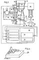
- the carburetor a schematic diagram of which is given in FIG. 1, comprises a body 10 made of several assembled parts in which an intake duct 12 is formed.
- the main fuel spouting system, opening at the neck of a venturi 14 of the duct d intake 12 is supplied with a rich primary air-fuel mixture from a constant level tank 16 and from the atmosphere.
- Calibrators 18 and 20 are interposed on the air and fuel inlets to the system.
- a throttle member, or butterfly, 22 is placed downstream of the venturi 14 and wedged on a rotary shaft 24 controlled by the driver by means of a linkage not shown.
- a return spring also not shown, biases the butterfly in the closing direction.
- Upstream of the venturi 14 is placed an air flap 26 mounted on an eccentric pin 28 so that the air flow sucked by the motor tends to bring it to the fully open position in which it is shown.
- the carburetor also has an idling circuit supplied with a rich primary air-fuel mixture by the main spouting system.
- This circuit opens into the intake duct 12 through an idle orifice 30 placed downstream of the throttle valve 22 and a transition or by-pass slot 32 intended to pass progressively from upstream to downstream of the throttle valve as the opening of the latter.
- a manual adjustment screw 34 makes it possible to adjust the flow rate which passes through the orifice 30 and therefore to adjust the richness of the mixture supplied to the engine during idling operation, while the end of the butterfly is downstream of the slot 32.
- the carburetor comprises a device intervening in particular during starting and cold starting of the engine to adjust the position of the flap 26 and that of the throttle valve 22.
- This device comprises a temperature-sensitive element 36, which will be designated by the continued by the usual term "wax capsule".
- This element is constituted by a closed enclosure occupied by a thermodilatable material which gives, to a rod 38 resting on it, a projection which increases with the temperature of the element. This temperature is adjustable by modulating the electric power applied to a heating resistor 40 in thermal contact with the enclosure.
- the rod 38 is coupled to an arm 42 integral with the axis 24 by an abutment link intended to give the butterfly a minimum open position depending on the position of the rod 38 and beyond which the butterfly can be opened by the driver's action.
- a mechanical linkage 44 also allows the wax capsule 36 to fix the position of the flap 26 as long as it is not in its fully open position, reached for a temperature of the wax capsule 36 lower than that which it takes during the operation of the engine under normal conditions.
- a temperature sensor 46 which may consist of a resistance with a negative temperature coefficient, is associated with the wax capsule 36 so as to supply an electrical signal which is a function of the temperature of the latter.
- the sensor 46 is connected, by a conductor 48, to one of the inputs of a calculating member 50 which may comprise, in a conventional manner, a microprocessor, a cartographic read-only memory whose role will appear below and a working RAM.
- a calculating member 50 which may comprise, in a conventional manner, a microprocessor, a cartographic read-only memory whose role will appear below and a working RAM.
- An analog-digital converter must in this case be provided to transform the analog signal from the sensor 46 into a digital signal.
- Other inputs of the calculation unit 50 are respectively connected to a sensor providing a signal depending on the speed N of the engine, to a sensor assembly placed on the gearbox and the clutch and providing a binary signal A indicating whether the motor is coupled or not, and to a sensor providing a binary signal 8 indicating whether or not the throttle valve 22 is close to its minimum opening position.
- the speed sensor can be constituted by a probe providing a pulse at each revolution of the ignition switch.
- a first output of the calculating member 50 comprises an actuator 52 supplying the heating resistor 40 with the electrical power required to maintain it at a set temperature ⁇ c determined according to a law which will be described later.
- a second output 54 controls the opening and closing of a solenoid valve 56 placed on the idle circuit of the carburetor, upstream of the slot 32.
- the calculating member 50 is designed to supply, on this output, a signal to pulse width modulation, variable duty cycle, allowing the richness of the mixture supplied to the engine to be adjusted at idle.
- the assembly consisting of the capsule 35, the arm 42 and the linkage 44 will be designed so as to give the butterfly 22 and the flap 26 an opening law as a function of the temperature of the capsule of the kind shown by the lines in solid line in Figures 2 and 3, respectively.
- the minimum opening a of the throttle valve 22 as a function of the temperature, shown by the curve 58 corresponds to a regular decrease as a function of the temperature, from the minimum temperature at which the engine must be able to start ( -30 ° C in the example illustrated) up to the maximum temperature that the wax capsule can take 36.
- the prior devices using a wax capsule were generally provided so that the minimum opening position of the butterfly imposed by the starting device reaches a minimum value for a determined temperature of the capsule and then stores it.
- This minimum opening position was fixed by the abutment of the butterfly against a mechanical stop, generally adjustable.
- the shape of the corresponding curve is represented by the dashed curve 58a.
- the mechanical stop will generally be eliminated on a carburetor according to the invention, which makes it possible to regulate the idle speed by acting on the temperature of the wax capsule 36. With this regulation, it is possible to adopt a setpoint Nc of the idling speed of the hot engine significantly lower than on simple manual adjustment carburetors. This idling speed Nc will be maintained regardless of the load applied to the engine, for example in the event of an increase in load due to the commissioning of an accessory, for example an air conditioning unit.
- the mixture supplied normally at idle speed can be adjusted “lean”, using the screw 34 for a nominal duty cycle of the signal applied to the solenoid valve 56, corresponding to permanent operation.
- This duty cycle will be temporarily modified by the calculating member 50 in a direction tending to increase the richness in the event of a drop in engine speed below Nc, with a short time constant, until the member calculation, operating in closed loop, will have brought the engine back to its set idle speed by action on the temperature of the wax capsule 36.
- This regulation, at a longer time constant is accompanied by a return to the duty cycle of instruction for the control of the solenoid valve 56.
- Another solution consists in providing a solenoid valve 56 closed at rest, placed in parallel with a calibrator providing the quantity of mixture required for normal idling operation.
- the law for controlling the opening of the air flap 26 could be that represented in FIG. 3 by the solid line 60, comparable to that, 60a, of a known type of carburetor with a wax capsule. It should simply be noted that the air flap arrives in its fully open position from a temperature of the wax capsule 36 much lower than the maximum temperature at which it can be brought into operation, for example at approximately 65 ° C. in the case illustrated in Figure 3.
- the programming of the calculation unit 50 will be carried out so as to obtain a start-up strategy by action on the air shutter 26 and the butterfly 22 using as essential input parameter the temperature 0 0 of the wax capsule at l time of engine launch (i.e. at room temperature in the event of a cold start) and the number of revolutions M made by the engine since launch (this last parameter can be replaced by the time elapsed since launch time).
- the speed regulation is carried out by all or nothing control of the heating power applied at resistance 40: if N> Nc, the heating power is applied to the wax capsule 36. If NK Nc, no heating is applied.
- the setpoint value Nc given to the motor will be stored in the read-only memory of the calculation unit 50 in the form of a table making a value Nc correspond to each pair of value ranges of 9 0 and M (or t).
- the part of the table immediately following the launch of the engine may for example be as follows:
- the calculation unit gradually reduces the setpoint speed Nc from its initial value. For example, there may be a reduction in the idling speed and the setpoint each time the calculating member 50 has received 2500 pulses indicating for each an ignition.
- the calculating member 50 regulates the temperature of the capsule 36 at a set value ⁇ c which, too, is a function of the starting temperature, with an increase in the set temperature in stages, each stage corresponding to a determined number of engine revolutions.
- ⁇ c is a function of the starting temperature
- the calculating member 50 causes the application of a heating "slot", for example of 5 ms, representing a determined quantity of heat, by the actuator 52 at each revolution of the engine. There is no heating if ⁇ > ⁇ c.
- the solenoid valve 56 can also be controlled to ensure a cut in deceleration, with recovery, programmed or not, from one or more thresholds of the speed N of the engine.
- the calculation unit 50 can also perform a deceleration cut-off, by supplying the solenoid valve 56 permanently (duty cycle of 100%) when at the same time the engine is coupled, the accelerator is not actuated and the speed N is greater than a threshold Nm.
- the corresponding flowchart is indicated in dashes in Figure 5.
- the calculating member can play the role of damper during the ignition cut-off, then suppressing the flow of primary mixture in the idle circuit.
- the solenoid valve 56 is advantageously of the type open at rest so that in the event of a failure of the electrical supply to the actuator, the conductor is not hampered by major operating faults.
- the usual drawback of such an arrangement namely the risk of self-ignition when the electrical contact is cut off, is eliminated by incorporating a time delay in the calculating member so that it keeps the solenoid valve closed for a few seconds after switching off.
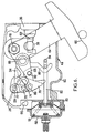
- the mechanical linkage 44 can have various constitutions, and in particular that shown in Figure 6 where the return springs are not shown, for simplicity.
- the return springs intended in particular to push the butterfly and the flap 26 towards their closed position, may be of the type described in document FR-A-2 257 790 to which reference may be made.
- a linkage is placed in a housing 60 fixed to the body 10 of the carburetor by means not shown, such as screws.
- the enclosure of the wax capsule 36 is fixed to the wall of the housing 60 and its rod 38 projects inside.
- This rod carries a pin trapped in a fork belonging to a bent lever 62 having a lower arm 64 terminated by a cam 66 forming a stop for the finger 42 (not shown) secured to the axis 24 of the butterfly 22.
- a second arm 68 is also completed by a cam which can come into abutment with a pin 70 secured to a plate 72 fixed to the axis 28 of the shutter and forming a lever.
- the cam has two consecutive surfaces, one, 74, designed to move the flap 26 in the opening direction by pressing on the pin 70, the other, 76, constituted by a circular edge centered on the axis 78 of the angled lever, intended to maintain the flap in its fully open position when the temperature of the capsule 36 is greater than a determined value (65 ° C. in the case illustrated in FIG. 3).
- the starting device also includes means sensitive to the vacuum prevailing downstream of the butterfly 22 to impose on the air flap a determined opening from the first engine explosions.
- These means consist of a membrane 80 placed in a housing 82 and subjected, on one side, to the pressure prevailing in the intake duct 12 downstream of the butterfly valve (brought by a pipe not shown) and, on the other, at atmospheric pressure.
- the membrane 80 is connected to a rod 83 whose curved end 84 has a unidirectional connection with one of the ends of a lever 86 articulated on an axis 88 carried by the lever 62.
- the other end of the lever 86 constitutes, for the pin 70 of the control lever 72, a stop which ensures a minimum opening of the flap 26 when a vacuum is established downstream of the butterfly valve.
- a spring 91 acting in the opposite direction to the pressure forces exerted on the membrane 80 tends to return the rod 82 to the rest position illustrated in Figure 1 in solid lines.
- the linkage 44 shown in Figure 6 is intended to present a hysteresis which facilitates the restarting of the hot engine during the first tens of minutes after stopping, taking into account that the thermal inertia of the engine is much greater than that of the carburetor and that, moreover, the normal temperature of the engine cooling water (80 to 100 ° C) is much higher than that of the carburetor (20 to 40 ° C).
- the wax capsule 36 cools down quickly while the engine is hot, and therefore causes the shutter to close gradually. But this closure is useless, and even often harmful, when the engine is restarted after a few minutes or even a few tens of minutes. Indeed, the engine is hot enough not to need enrichment.
- the linkage of Figure 6 includes means for maintaining the flap in the fully open position, upon cooling, to a temperature lower than that which corresponds to complete opening during heating.
- this hysteresis corresponds to the curve indicated in dashes, indicating that the full opening is maintained up to approximately 35 ° C., then a fall back on the normal curve of variation of the opening as a function of the temperature.
- the device can in this case be supplemented by means (bistable circuit whose inputs are connected to two comparators with respective thresholds of 150 revolutions / minute and 350 revolutions / minute for example) which in all cases cause heating as soon as the engine is started if the starter speed exceeds 150 rpm.
- the invention is obviously not limited to the particular mode of execution which has been shown and described by way of example and, moreover, the calculating member can fulfill functions in addition to those which have been described or substituting for them.
Landscapes
- Engineering & Computer Science (AREA)
- Chemical & Material Sciences (AREA)
- Combustion & Propulsion (AREA)
- Mechanical Engineering (AREA)
- General Engineering & Computer Science (AREA)
- Means For Warming Up And Starting Carburetors (AREA)
- Control Of Throttle Valves Provided In The Intake System Or In The Exhaust System (AREA)
Claims (8)
Applications Claiming Priority (2)
| Application Number | Priority Date | Filing Date | Title |
|---|---|---|---|
| FR8412350A FR2568631B1 (fr) | 1984-08-03 | 1984-08-03 | Carburateur a dispositif de depart automatique |
| FR8412350 | 1984-08-03 |
Publications (2)
| Publication Number | Publication Date |
|---|---|
| EP0170595A1 EP0170595A1 (de) | 1986-02-05 |
| EP0170595B1 true EP0170595B1 (de) | 1988-05-11 |
Family
ID=9306799
Family Applications (1)
| Application Number | Title | Priority Date | Filing Date |
|---|---|---|---|
| EP85401595A Expired EP0170595B1 (de) | 1984-08-03 | 1985-08-05 | Vergaser mit Startautomatik |
Country Status (7)
| Country | Link |
|---|---|
| US (1) | US4662333A (de) |
| EP (1) | EP0170595B1 (de) |
| JP (1) | JPS6158960A (de) |
| BR (1) | BR8503666A (de) |
| DE (1) | DE3562648D1 (de) |
| ES (1) | ES8607479A1 (de) |
| FR (1) | FR2568631B1 (de) |
Families Citing this family (20)
| Publication number | Priority date | Publication date | Assignee | Title |
|---|---|---|---|---|
| IT1207534B (it) * | 1987-02-17 | 1989-05-25 | Weber Srl | Termico provvisto di alimentazione sistema di controllo del regime di ad iniezione elettronica rotazione minimo di un motore endo |
| IT1218998B (it) * | 1988-02-05 | 1990-04-24 | Weber Srl | Sistema di imiezione elettronica di carburante per motori a scoppio |
| US4873954A (en) * | 1988-07-27 | 1989-10-17 | Colt Industries Inc. | Fail-safe idle bypass system |
| US4873955A (en) * | 1988-09-19 | 1989-10-17 | Colt Industries Inc. | Idle air flow shutoff valve |
| JPH02108840A (ja) * | 1988-10-19 | 1990-04-20 | Fuji Heavy Ind Ltd | 気化器のアイドリング回転数制御装置 |
| JP3543119B2 (ja) * | 1993-09-08 | 2004-07-14 | ヤマハマリン株式会社 | エンジン始動制御装置 |
| JP3764187B2 (ja) * | 1995-06-02 | 2006-04-05 | ヤマハマリン株式会社 | エンジン始動制御装置 |
| JP3724656B2 (ja) * | 1995-11-28 | 2005-12-07 | 本田技研工業株式会社 | バイスター装置 |
| US5660765A (en) * | 1996-06-26 | 1997-08-26 | Kohler Co. | Thermostatic element for controlling a solenoid operated carburetor choke |
| JP3925073B2 (ja) * | 2000-10-27 | 2007-06-06 | スズキ株式会社 | 燃料噴射式エンジンの吸気制御装置 |
| EP1621754B1 (de) * | 2004-07-26 | 2013-04-24 | Honda Motor Co., Ltd. | Automatische Kaltstartvorrichtung für Vergaser |
| JP2008255881A (ja) * | 2007-04-04 | 2008-10-23 | Kyoto Denkiki Kk | エンジン |
| JP4868523B2 (ja) * | 2007-04-04 | 2012-02-01 | 京都電機器株式会社 | エンジンにおけるオートチョーク装置 |
| US7650865B2 (en) * | 2007-05-07 | 2010-01-26 | Honda Motor Company, Ltd. | Power equipment apparatus having engine with electric starter motor and manual starter mechanism |
| US8146558B2 (en) * | 2007-08-13 | 2012-04-03 | Briggs & Stratton Corporation | Automatic choke for an engine |
| US8219305B2 (en) * | 2008-05-27 | 2012-07-10 | Briggs & Stratton Corporation | Engine with an automatic choke and method of operating an automatic choke for an engine |
| US7628387B1 (en) | 2008-07-03 | 2009-12-08 | Briggs And Stratton Corporation | Engine air/fuel mixing apparatus |
| US9638135B2 (en) * | 2013-07-31 | 2017-05-02 | Walbro Llc | Fuel shut-off solenoid system |
| WO2015023885A2 (en) | 2013-08-15 | 2015-02-19 | Kohler Co. | Systems and methods for electronically controlling fuel-to-air ratio for an internal combustion engine |
| US10054081B2 (en) | 2014-10-17 | 2018-08-21 | Kohler Co. | Automatic starting system |
Family Cites Families (13)
| Publication number | Priority date | Publication date | Assignee | Title |
|---|---|---|---|---|
| US3740040A (en) * | 1971-10-07 | 1973-06-19 | Gen Motors Corp | Carburetor with power choke |
| US3763837A (en) * | 1972-07-14 | 1973-10-09 | Gen Motors Corp | Automatic choke control |
| FR2288224A1 (fr) * | 1974-10-18 | 1976-05-14 | Sibe | Perfectionnements aux dispositifs de depart pour carburateurs |
| US4237077A (en) * | 1978-08-29 | 1980-12-02 | Texas Instruments Incorporated | Automatic choke system |
| DE2927881C2 (de) * | 1979-07-11 | 1984-06-28 | Bosch und Pierburg System oHG, 4040 Neuss | Verfahren und Vorrichtung zur Übergangsanreicherung bei Gemischbildnern |
| JPS5623545A (en) * | 1979-08-02 | 1981-03-05 | Fuji Heavy Ind Ltd | Air-fuel ratio controller |
| DE3028091C2 (de) * | 1979-08-02 | 1985-09-12 | Fuji Jukogyo K.K., Tokio/Tokyo | Luftbrennstoffverhältnisregelsystem für einen Verbrennungsmotor |
| US4463723A (en) * | 1982-04-01 | 1984-08-07 | Acf Industries, Incorporated | Apparatus for controllably opening a carburetor choke valve |
| JPS58178854A (ja) * | 1982-04-14 | 1983-10-19 | Aisan Ind Co Ltd | 温度センサによるエンジン制御装置 |
| JPS5974358A (ja) * | 1982-10-20 | 1984-04-26 | Nippon Carbureter Co Ltd | 気化器の自動チヨ−ク装置 |
| IT1157490B (it) * | 1982-12-20 | 1987-02-11 | Weber Spa | Carburatore per motori a combustione interna provvisto di organi ad azione elettronica atti a mantenere costante il minimo regime del motore ed a controllare la posizione della farfalla di avviamento durante la messa in efficienza del motore |
| JPS59136526A (ja) * | 1983-01-27 | 1984-08-06 | Honda Motor Co Ltd | スロツトル弁の完爆開度制御装置 |
| US4498440A (en) * | 1984-04-02 | 1985-02-12 | Honda Giken Kogyo Kabushiki Kaisha | Mixture control apparatus for carburetor |
-
1984
- 1984-08-03 FR FR8412350A patent/FR2568631B1/fr not_active Expired
-
1985
- 1985-08-01 ES ES545790A patent/ES8607479A1/es not_active Expired
- 1985-08-02 JP JP60169910A patent/JPS6158960A/ja active Pending
- 1985-08-02 BR BR8503666A patent/BR8503666A/pt not_active IP Right Cessation
- 1985-08-05 EP EP85401595A patent/EP0170595B1/de not_active Expired
- 1985-08-05 US US06/762,278 patent/US4662333A/en not_active Expired - Fee Related
- 1985-08-05 DE DE8585401595T patent/DE3562648D1/de not_active Expired
Also Published As
| Publication number | Publication date |
|---|---|
| FR2568631B1 (fr) | 1987-01-16 |
| ES545790A0 (es) | 1986-06-16 |
| FR2568631A1 (fr) | 1986-02-07 |
| DE3562648D1 (en) | 1988-06-16 |
| ES8607479A1 (es) | 1986-06-16 |
| US4662333A (en) | 1987-05-05 |
| JPS6158960A (ja) | 1986-03-26 |
| BR8503666A (pt) | 1986-05-06 |
| EP0170595A1 (de) | 1986-02-05 |
Similar Documents
| Publication | Publication Date | Title |
|---|---|---|
| EP0170595A1 (de) | Vergaser mit Startautomatik | |
| JP6105361B2 (ja) | 汎用内燃機関の制御装置 | |
| FR2855215A1 (fr) | Procede de mise en oeuvre d'un moteur a combustion interne | |
| FR2851302A1 (fr) | Procede de gestion d'un moteur a combustion interne | |
| FR2541726A1 (fr) | Methode de commande du regime de ralenti d'un moteur a combustion interne prevue pour ameliorer la caracteristique de consommation de carburant du moteur | |
| FR2461110A1 (fr) | Procede et dispositif pour operer un enrichissement transitoire du melange dans des systemes de formation du melange munis d'un dispositif d'enrichissement a chaud commande par un moteur electrique | |
| EP0651152A1 (de) | Verfahren zur Steuerung einer Brennstoffpumpe für eine Brennkraftmaschine | |
| EP0262027B1 (de) | Vergaser mit Startautomatik | |
| FR2541728A1 (fr) | Procede de reglage du ralenti par reaction dans un moteur a combustion interne | |
| FR2571097A1 (fr) | Dispositif de reflux des gaz d'echappement. | |
| FR3012520A1 (fr) | Ligne d'echappement de moteur a combustion interne | |
| FR3064683A1 (fr) | Procede de controle d'un moteur a allumage commande suralimente avec recirculation partielle des gaz d'echappement, et dispositif de motorisation associe | |
| FR2981987A1 (fr) | Commande d'un moteur a combustion interne | |
| FR2478202A1 (fr) | Dispositif de carburation pour moteur a combustion interne | |
| EP1008739A1 (de) | Brennkraftmaschine mit einem Abgasturbolader | |
| FR2821121A1 (fr) | Procede et dispositif de commande d'un compresseur a entrainement mecanique d'un moteur a combustion interne | |
| EP0113268B1 (de) | Kaltstartautomatik für Vergaser | |
| FR2985288A1 (fr) | Procede de commande d'un organe dans la conduite d'alimentation en air d'un moteur thermique notamment du volet d'etranglement | |
| EP1076177B1 (de) | Anlassverfahren für eine fremdgezündete Brennkraftmaschine | |
| FR2526492A1 (fr) | Systeme de commande de papillon pour moteurs a combustion interne | |
| FR2713718A1 (fr) | Dispositif d'injection multipoints à injecteurs assistés par air et papillon à commande électronique. | |
| EP0240409B1 (de) | Verfahren zur Kontrolle der Kraftstoffzufuhr zu einer Brennkraftmaschine nach Beendigung einer Kraftstoffabsperrung im Schiebebetrieb | |
| FR2470255A2 (fr) | Perfectionnements aux carburateurs comportant un dispositif auxiliaire de depart | |
| EP0052026B1 (de) | Automatische Starterklappenvorrichtung für Doppelvergaser | |
| FR2509378A1 (fr) | Carburateur avec commande automatique du volet de depart a froid |
Legal Events
| Date | Code | Title | Description |
|---|---|---|---|
| PUAI | Public reference made under article 153(3) epc to a published international application that has entered the european phase |
Free format text: ORIGINAL CODE: 0009012 |
|
| AK | Designated contracting states |
Designated state(s): DE GB IT |
|
| 17P | Request for examination filed |
Effective date: 19860306 |
|
| 17Q | First examination report despatched |
Effective date: 19861014 |
|
| GRAA | (expected) grant |
Free format text: ORIGINAL CODE: 0009210 |
|
| AK | Designated contracting states |
Kind code of ref document: B1 Designated state(s): DE GB IT |
|
| GBT | Gb: translation of ep patent filed (gb section 77(6)(a)/1977) | ||
| REF | Corresponds to: |
Ref document number: 3562648 Country of ref document: DE Date of ref document: 19880616 |
|
| ITF | It: translation for a ep patent filed | ||
| PLBE | No opposition filed within time limit |
Free format text: ORIGINAL CODE: 0009261 |
|
| STAA | Information on the status of an ep patent application or granted ep patent |
Free format text: STATUS: NO OPPOSITION FILED WITHIN TIME LIMIT |
|
| 26N | No opposition filed | ||
| PGFP | Annual fee paid to national office [announced via postgrant information from national office to epo] |
Ref country code: GB Payment date: 19920728 Year of fee payment: 8 |
|
| ITTA | It: last paid annual fee | ||
| PGFP | Annual fee paid to national office [announced via postgrant information from national office to epo] |
Ref country code: DE Payment date: 19920929 Year of fee payment: 8 |
|
| PG25 | Lapsed in a contracting state [announced via postgrant information from national office to epo] |
Ref country code: GB Effective date: 19930805 |
|
| GBPC | Gb: european patent ceased through non-payment of renewal fee |
Effective date: 19930805 |
|
| PG25 | Lapsed in a contracting state [announced via postgrant information from national office to epo] |
Ref country code: DE Effective date: 19940503 |