EP0177817B1 - Antiblockierregelsystem - Google Patents
Antiblockierregelsystem Download PDFInfo
- Publication number
- EP0177817B1 EP0177817B1 EP85111919A EP85111919A EP0177817B1 EP 0177817 B1 EP0177817 B1 EP 0177817B1 EP 85111919 A EP85111919 A EP 85111919A EP 85111919 A EP85111919 A EP 85111919A EP 0177817 B1 EP0177817 B1 EP 0177817B1
- Authority
- EP
- European Patent Office
- Prior art keywords
- pressure
- control system
- pulse
- wheel
- pressure build
- Prior art date
- Legal status (The legal status is an assumption and is not a legal conclusion. Google has not performed a legal analysis and makes no representation as to the accuracy of the status listed.)
- Expired
Links
- 230000001133 acceleration Effects 0.000 claims abstract description 16
- 230000001419 dependent effect Effects 0.000 claims description 6
- 238000005259 measurement Methods 0.000 claims description 4
- 230000007423 decrease Effects 0.000 claims description 3
- 238000009530 blood pressure measurement Methods 0.000 claims description 2
- 238000011156 evaluation Methods 0.000 description 8
- 238000010586 diagram Methods 0.000 description 7
- 238000001514 detection method Methods 0.000 description 3
- 239000012530 fluid Substances 0.000 description 2
- 230000015654 memory Effects 0.000 description 2
- 230000006978 adaptation Effects 0.000 description 1
- 238000013459 approach Methods 0.000 description 1
- 230000000903 blocking effect Effects 0.000 description 1
- 238000010276 construction Methods 0.000 description 1
- 238000013461 design Methods 0.000 description 1
- 238000006073 displacement reaction Methods 0.000 description 1
- 238000000034 method Methods 0.000 description 1
- 238000005096 rolling process Methods 0.000 description 1
- 230000036962 time dependent Effects 0.000 description 1
Images


Classifications
-
- B—PERFORMING OPERATIONS; TRANSPORTING
- B60—VEHICLES IN GENERAL
- B60T—VEHICLE BRAKE CONTROL SYSTEMS OR PARTS THEREOF; BRAKE CONTROL SYSTEMS OR PARTS THEREOF, IN GENERAL; ARRANGEMENT OF BRAKING ELEMENTS ON VEHICLES IN GENERAL; PORTABLE DEVICES FOR PREVENTING UNWANTED MOVEMENT OF VEHICLES; VEHICLE MODIFICATIONS TO FACILITATE COOLING OF BRAKES
- B60T8/00—Arrangements for adjusting wheel-braking force to meet varying vehicular or ground-surface conditions, e.g. limiting or varying distribution of braking force
- B60T8/17—Using electrical or electronic regulation means to control braking
- B60T8/176—Brake regulation specially adapted to prevent excessive wheel slip during vehicle deceleration, e.g. ABS
- B60T8/1761—Brake regulation specially adapted to prevent excessive wheel slip during vehicle deceleration, e.g. ABS responsive to wheel or brake dynamics, e.g. wheel slip, wheel acceleration or rate of change of brake fluid pressure
- B60T8/17616—Microprocessor-based systems
-
- Y—GENERAL TAGGING OF NEW TECHNOLOGICAL DEVELOPMENTS; GENERAL TAGGING OF CROSS-SECTIONAL TECHNOLOGIES SPANNING OVER SEVERAL SECTIONS OF THE IPC; TECHNICAL SUBJECTS COVERED BY FORMER USPC CROSS-REFERENCE ART COLLECTIONS [XRACs] AND DIGESTS
- Y10—TECHNICAL SUBJECTS COVERED BY FORMER USPC
- Y10S—TECHNICAL SUBJECTS COVERED BY FORMER USPC CROSS-REFERENCE ART COLLECTIONS [XRACs] AND DIGESTS
- Y10S303/00—Fluid-pressure and analogous brake systems
- Y10S303/02—Brake control by pressure comparison
- Y10S303/03—Electrical pressure sensor
- Y10S303/04—Pressure signal used in electrical speed controlled braking circuit
Definitions
- the invention relates to an anti-lock control system with the features of the preamble of claim 1.
- Such an anti-lock control system is known from FIG. 2 of DE-A-24 60 904.
- the pressure build-up period is made dependent on the duration of the previous pressure drop or on the pressure difference built up on the first pressure drop or also on the vehicle deceleration or temperature of the brake fluid.
- the invention aims for an optimal dimensioning of the pressure build-up pulse following the pressure reduction. This is achieved with the features of independent claim 1. Particular embodiments of the invention are specified in the dependent claims.
- a is slightly less than 1, e.g. B. 0.9.
- the dynamics of the wheel including the grip on the road and disturbances in the controlled system are reliably detected, so that the subsequent pressure build-up pulse can be optimally dimensioned. This ensures optimal braking distances and great vehicle stability.
- the detection of the wheel brake pressure can also be used to actively control the pressure adjustment Ap 2 in such a way that the pressure builds up more slowly than usual during corner braking, whereby the wheel is guided longer in a stable area, so that stability and steerability are increased .
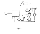
- FIG. 1 denotes a sensor assigned to a vehicle wheel, which feeds a signal, which is dependent on the wheel speed, to an evaluation circuit 2, which generates brake pressure control signals for an inlet valve 6 and an outlet valve 6.
- These valves 5 and 6 are switched on or on in a brake line between a master cylinder 3 actuated by a pedal 5 and a wheel brake 7.
- a return flow for the brake fluid discharged from the outlet valve 6 bears the reference number 8, a pressure meter, the signal of which is dependent on the pressure at the brake 7 and is fed to the evaluation circuit 2, reference number 9.
- the evaluation circuit 2 generates pressure reduction (p,), pressure constant ( Pe ) and pressure build-up signals (p 2 ) in a manner known per se.
- the pressure build-up signal represents the command for the start and duration of the pressure build-up.
- the way in which pressure is built up in this time period is determined by an evaluation circuit part contained in the evaluation circuit 2, which is shown in an exemplary block diagram in FIG.
- the evaluation circuit 2 has a Differentiator, not shown, which forms a signal corresponding to the wheel speed signal w from the wheel speed signal ⁇ .
- Figure 2 shows the logic diagram for the pressure build-up control.
- a maximum circuit 21 and a minimum circuit 22 form the extreme values of the wheel angle acceleration + ⁇ m and - ⁇ m from the wheel angle acceleration ⁇ .
- the amounts of blocks 21 and 22 are added in an adder 33.
- a divider 24 forms the quotient
- the wheel brake pressure p measured with the pressure gauge 9 at the beginning of the pressure reduction (p 1 beginning) and at the end of the pressure reduction (P 1 end; inverter 25) is stored in two memories 25 and 27.
- the P 1 start signal also resets extreme value circuits 21 and 22, respectively.
- the difference between these pressures and thus the pressure stage ⁇ P1 is formed in a subtractor 28.
- the output value of subtractor 28 is multiplied in a multiplier 29 by a - 0.9 from block 43.
- the factor a can be reduced when cornering by means of a steering angle meter 42.
- the multiplication by the output of the divider 24 then takes place in a further multiplier 30, so that at the output of the multiplier 30 a term corresponding signal is present.
- the calculated pressure build-up pulse JD p 2 is added to the wheel brake pressure level stored in the memory 27 after the pressure reduction.
- a comparator 32 generates a logic 1 which controls the inlet valve 5 via an AND gate 33 and an OR gate 34, ie, which stops the pressure build-up.
- the AND gate 33 can only be switched through if a flip-flop 39 has been set at the terminal 40 by the "pressure build-up" signal. This flip-flop is reset by the signal "p 1 ".
- the inlet valve 5 is pulsed by means of the links 31, 32, 33 and an OR gate 34.
- the signals emitted by the converter 35, which determine the level of the further pressure build-up pulses JD p can be of different heights.
- the brake pressure in the wheel brake 7 is measured here by the pressure meter 9.
- the pressure measurement in master cylinder arrangements in twin construction can also be carried out by scanning the master cylinder piston paths if the master brake cylinder is adjusted by the anti-lock control, which represents a particularly economical measuring method.
- a signal for the inlet valve is coupled in via a terminal 41 when pressure reduction or keeping constant is required.
- a lateral accelerometer 10 is shown for the vehicle. Its output signal is differentiated in a block 11 and its signal is fed to the evaluation circuit 2. This supplied signal causes the pressure reduction period to be extended when the lateral acceleration decreases.
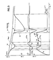
- FIG. 3 shows the course of the vehicle speed VF , the reference speed v Ref for the slip measurement and the wheel angular speed ⁇ for an assumed braking course with anti-lock control and u-jump.
- the extreme values - ⁇ m and + ⁇ m in the first control cycle are shown in the curve below for the wheel angle acceleration ⁇ .
- the lower diagram shows the pressure curve and the measured pressure value ⁇ P1 and the determined pressure value A p 2 for the first pressure build-up pulse and Ap for the further pulses.
- the points designated by the letters AD correspond to the points AD in FIGS. 4 and 5. There, the braking torque M BR or the road friction torque M R is plotted over the brake slip.
- FIG. 4 shows the principle of the pressure build-up measurement, depending on the pressure reduction stage ⁇ P1 and the maximum wheel angle accelerations + ⁇ m and - ⁇ m .
- the braking torque M BR is approximately proportional to the braking pressure.
- the braking torque M BR initially increases according to the curve from A to B, the braking slip increasing.
- the brake pressure reduction is started, namely by the amount Ap along the curve BC.
- the maximum wheel angle deceleration - ⁇ m arises between the braking torque in point B and the road friction torque M R.
- the pressure is kept constant along the curve CD, the maximum angular acceleration + ⁇ m occurs between the braking torque M BR in this area and the friction torque M R.
- the pressure is at point D by the amount ⁇ P2 . increased (according to E).
- FIG. 5 shows the optimal adaptation of the pressure build-up dimensioning to the sudden change in the road friction coefficient (p jump) assumed here. Shortly before reaching point C, a ⁇ jump from M R1 to M R2 takes place. The figure shows that the pressure level Ap 2 is optimally determined. The observation of the above equation shows that in this example this is due to the very large term -w m , which results in the relatively small pressure build-up level Ap 2 .
Landscapes
- Engineering & Computer Science (AREA)
- Microelectronics & Electronic Packaging (AREA)
- Physics & Mathematics (AREA)
- Fluid Mechanics (AREA)
- Transportation (AREA)
- Mechanical Engineering (AREA)
- Regulating Braking Force (AREA)
- Braking Arrangements (AREA)
Description
- Die Erfindung betrifft ein Antiblockierregelsystem mit den Merkmalen des Oberbegriffs des Anspruches 1.
- Ein derartiges Antiblockierregelsystem ist aus der Figur 2 der DE-A-24 60 904 bekannt. Dort wird grundsätzlich vorgeschlagen, den ersten Druckaufbauimpuls nach einer Druckabsenkung abhängig zu machen von dem Druckaufbau in einem oder mehreren vorhergehenden Regelzyklen. Für den ersten Regelzyklus, bei dem es keinen Druckaufbau in einem vorhergehenden Regelzyklus gibt, wird die Druckaufbaudauer abhängig gemacht von der Dauer der vorhergehenden Druckabsenkung oder von der errichten Druckdifferenz bei der ersten Druckabsenkung oder auch von der Fahrzeugverzögerung oder Temperatur der Bremsflüssigkeit.
- Der Erfindung bezweckt bei einem Antiblockierregelsystem der eingangs genannten Art eine optimale Bemessung des auf den Druckabbau folgenden Druckaufbauimpulses. Dies wird mit den Merkmalen des unabhängigen Anspruchs 1 erreicht. Besondere Ausführungsarten der Erfindung sind in den abhängigen Ansprüchen angegeben.
- Bei dem erfindungsgemäßen Antiblockierregelsystem wird grundsätzlich eine Verknüpfung des vorhergehenden Druckabbaus mit einem Ausdruck vorgeschlagen, der die maximale Radwinkelverzögerung -o und maximale Radwinkelbeschleunigung +00 berücksichtigt. Hierdurch wird ein sehr viel feinfühligeres Heranführen des Bremsdrucks an den Druck möglich, an dem die Instabilität einsetzt. Besonders vorteilhaft ist es, die angegebene Bemessung des Druckaufbauimpulses mit einer Druckregelung zu verbinden, d.h., den Bremsdruck zu messen und rückzuführen, so daß tatsächlich auf den vorbestimmten Druckwert ΔP2 eingeregelt wird. Wegen der vielen eingehenden Parameter kann mit der bekannten zeitabhängigen Druckeinsteuerung diese Genauigkeit nicht erreicht werden.
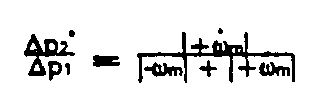
- Dagegen wird es mit der obige Kombination möglich, nach erfolgtem Druckabbau und anschließender Druckhaltephase den Druck mit einer ersten Druckstufe soweit anzuheben, daß der Blockierdruck nahezu erreicht wird. Dies wird bei der Bemessung gemäß folgender Formel erreicht:
-

- Durch die Erfassung und Berücksichtigung der maximalen Winkelverzögerung -wm und -beschlueunigung +ω̇m wird die Dynamik des Rades einschließlich der Fahrbahngriffigkeit und Störungen in der Regelstrecke zuverlässig erfaßt, so daß der anschließende Druckaufbauimpuls optimal bemessen werden kann. Dies sichert optimale Bremswege und eine große Fahrzeugstabilität.
- Die Erfassung des Radbremsdruckes kann weiter dazu benutzt werden, die Druckanpassung Ap2 aktiv in der Weise zu steuern, daß bei Kurvenbremsungen der Druck langsamer als sonst aufgebaut wird, wodurch das Rad länger im stabilen Gebiet geführt wird, so daß Stabilität bzw. Lenkbarkeit erhöht sind. Darüber hinaus ist es möglich, durch Differenzieren der Querbeschleunigung, d.h., durch die Erfassung der Querbeschleunigungsabnahme beim Bremsvorgang einen definierten Druckabbau so zu bemessen, daß das Rad mit geringem Bremsschlupf und großer Seitenstabilität läuft.
- Der erwähnte Gedanke, mit Hilfe der Erfassung des Druckes eine optimale Druckanpassung zu erreichen, ist besonders wirtschaftlich, wenn Geber, die ohnehin systembedingt eingesetzt werden, für die Druckerfassung mitverwendet werden können, wie z. B. bei elektronischen Bremssystemen oder auch bei Bremssystemen mit Wegsimulator und Verstellung des Hauptbremszylinders durch die Regelung, deren Hauptzylinderkolbenwege mit Sensoren abgetastet werden können.
- Anhand der Zeichnung soll ein Ausführungsbeispiel der Erfindung näher erläutert werden.
- Es zeigen:
- Fig. 1 - eine Prinzipdarstellung eines erfindungsgemäßen Antiblockierregelsystems,
- Fig. 2 - ein Blockschaltbild eines Teils der Auswerteschaltung,
- Fig. 3 - ein Diagramm zur Erläuterung der Wirkungsweise,
- Fig. 4 und 5 - Momenten-Diagramme über dem Bremsschlupf.
- In Figur 1 ist mit 1 ein einem Fahrzeugrad zugeordneter Meßwertgeber bezeichnet, der ein von der Radgeschwindigkeit abgehängiges Signal einer Auswerteschaltung 2 zuführt, die Bremsdrucksteuersignale für ein Einlaßventil 6 und ein Auslaßventil 6 erzeugt. Diese Ventile 5 und 6 sind in bzw. an eine Bremsleitung zwischen einem durch ein Pedal 5 betätigten Hauptbremszylinder 3 und einer Radbremse 7 ein- bzw. angeschaltet.
- Eine Rückförderung für die vom Auslaßventil 6 abgelassene Bremsflüssigkeit trägt das Bezugszeichen 8, ein Druckmesser, dessen vom Druck an der Bremse 7 abhängiges Signal der Auswerteschaltung 2 zugeführt wird, das Bezugszeichen 9.
- Die Auswerteschaltung 2 erzeugt in an sich bekannter Weise Druckabbau- (p,), Druckkonstanthaltungs- (Pe) und Druckaufbausignale (p2). Das Druckaufbausignal stellt dabei den Befehl für den Beginn und die Dauer des Druckaufbaus dar. Die Art, wie in dieser Zeitspanne Druck aufgebaut wird, wird durch ein in der Auswerteschaltung 2 enthaltenen Auswerteschaltungsteil bestimmt, das in einem beispielhaften Blockschaltbild in Figur 2 dargestellt ist. Die Auswerteschaltung 2 weist ein nicht dargestelltes Differenzierglied auf, das aus dem Radgeschwindigkeitssignal σ ein dem Radgeschwindigkeitssignal w entsprechendes Signal bildet.
- Figur 2 zeigt den Logikplan für die Druckaufbausteuerung. Aus der Radwinkelbeschleunigung ω̇ bilden eine Maximumschaltung 21 und eine Minimumschaltung 22 die Extremwerte der Radwinkelbeschleunigung +ω̇m und -ω̇m. In einen Addierer 33 werden die Beträge der Blöcke 21 und 22 addiert. Ein Dividierer 24 bildet den Quotienten

- In zwei Speichern 25 und 27 wird der mit dem Druckmesser 9 gemessene Radbremsdruck p zu Beginn des Druckabbaus (p1-Beginn) und am Ende des Druckabbaus (P1-Ende; Inverter 25) gespeichert. Das P1-Beginn-Signal setzt auch jeweils die Extremwertschaltungen 21 und 22 zurück. In einem Subtrahierer 28 wird die Differenz dieser Drücke und somit die Druckstufe ΔP1 gebildet. Der Ausgangswert des Subtrahierers 28 wird in einem Multiplizierer 29 mit a - 0,9 aus dem Block 43 multipliziert. Mittels eines Lenkwinkelmessers 42 kann der Faktor a bei Kurvenfahrt verkleinert werden. In einem weiteren Multiplizierer 30 erfolgt dann die Multiplikation mit dem Ausgang des Dividierers 24, so daß am Ausgang des Multiplizierers 30 ein dem Term

- In einem weiteren Addierer 31 wird zum im Speicher 27 gespeicherten Radbremsdruckniveau nach dem Druckabbau der errechnete Druckaufbauimpuls JD p2 hinzuaddiert. Sobald der vom Druckmesser 9 ermittelte Radbremsdruck das im Addierer 31 gebildete Druckniveau überschreitet, erzeugt ein Komparator 32 eine logische 1, die über ein UND-Glied 33 und ein ODER-Glied 34 das Einlaßventil 5 ansteuert, d.h,, den Druckaufbau stoppt. Das UND-Glied 33 ist nur dann durchschaltbar, wenn ein Flip-Flop 39 durch das Signal "Druckaufbau" an der Klemme 40 gesetzt wurde. Durch das Signal "p1" wird dieses Flip-Flop zurückgesetzt.
- Die erwähnten kleinen Druckaufbaustufen, die auf den errechneten ersten Druckaufbaupuls JD p2 folgen, werden in einem Pulszähler 37 aufbereitet, der über ein Zeitglied 35, das jeweils die Haltephase bestimmt, angesteuert wird. Über einen Wandler 36 werden Signale einem Addierer 38 zugeführt. Über die Glieder 31, 32, 33 und ein ODER-Gatter 34 erfolgt das pulsförmige Ansteuern des Einlaßventils 5. Die vom Wandler 35 abgegebenen Signale, die die Höhe der weiteren Druckaufbauimpulse JD p bestimmen, können unterschiedlich hoch sein.
- Der Bremsdruck in der Radbremse 7 wird hier vom Druckmesser 9 gemessen. Die Druckmessung kann bei Hauptzylinderanordnungen in Twinbauweise auch durch eine Abtastung der Hauptzylinderkolbenwege erfolgen, wenn der Hauptbremszylinder durch die Antiblockierregelung verstellt wird, was eine besonders wirtschaftliche Meßmethode darstellt. Über eine Klemme 41 wird ein Signal für das Einlaßventil eingekoppelt, wenn Druckabbau oder Konstanthaltung verlangt wird. In Fig. 1 ist noch ein Querbeschleunigungsmesser 10 für das Fahrzeug dargestellt. Sein Ausgangssignal wird in einem Block 11 differenziert und dessen Signal der Auswerteschaltung 2 zugeführt. Dieses zugeführte Signal bewirkt eine Verlängerung des Druckabbauzeitraums, wenn die Querbeschleunigung abnimmt.
- In Figur 3 ist oben der Verlauf der Fahrzeuggeschwindigkeit VF, der Referenzgeschwindigkeit vRef für die Schlupfmessung und der Radwinkelgeschwindigkeit ω für einen angenommenen Bremsverlauf mit Antiblockierregelung und u-Sprung dargestellt. In dem darunter befindlichen Verlauf für die Radwinkelbeschleunigung ω̇ sind die Extremwerte -ωm und +ωm im ersten Regelzyklus eingezeichnet. Das untere Diagramm gibt den Druckverlauf und den gemessenen Druckwert ΔP1 und den ermittelten Druckwert A p2 für den ersten Druckaufbauimpuls sowie Ap für die weiteren Impulse wieder.
- Die mit den Buchstaben A-D bezeichneten Punkte entsprechen den Punkten A-D in den Figuren 4 und 5. Dort ist über dem Bremsschlupf das Bremsmoment MBR bzw. das Fahrbahnreibmoment MR aufgetragen.
- Figur 4 zeigt das Prinzip der Druckaufbaumessung, abhängig von der Druckabbaustufe ΔP1 und den maximalen Radwinkelbeschleunigungen +ωm und -ωm. Das Fahrbahnreibmoment ist gegeben zu MR = µB N - r, wobei µB der Reibkoeffizient zwischen Rad und Fahrbahn, N die Aufstandskraft des Rades und r der dynamische Rollradius des Rades ist. Da Bremsmoment MBR ist angenähert proportional zum Bremsdruck.
- Beim Abbremsen wächst zunächst das Bremsmoment MBR gemäß dem Kurvenzug von A nach B an, wobei der Bremsschlupf zunimmt. Im Punkt B wird der Bremsdruckabbau begonnen und zwar um den Betrag Ap, längs des Kurvenzuges B-C.
- Zwischen dem Bremsmoment in Punkt B und dem Fahrbahnreibmoment MR entsteht die maximale Radwinkelverzögerung -ωm. Längs des Kurvenzuges C-D wird der Druck konstant gehalten, zwischen dem Bremsmoment MBR in diesem Bereich und dem Reibmoment MR tritt die maximale Winkelbeschleunigung +ω̇m auf. Der Druck, wird im Punkt D um den Betrag ΔP2. erhöht (nach E).
- Aus dieser Figur läßt sich die Beziehung
- Wählt man statt AP2 für den Druckabbau AP2 = α . ΔP2* und a zu 0,9, so erhält man die schon bekannte Gleichung

- Aus der Figur 5 ergibt sich die optimale Anpassung der Druckaufbaubemessung an der hier angenommenen sprungartigen Änderung des Fahrbahnreibwertes (p-Sprung). Kurz vor Erreichen des Punktes C findet ein µ-Sprung vom MR1 auf MR2 statt. Die Figur zeigt, daß die Druckstufe Ap2 optimal festgelegt wird. Die Betrachtung obiger Gleichung zeigt, daß dies in diesem Beispiel auf den sehr großen Term -wm zurückzuführen ist, der die verhältnismäßig kleine Druckaufbaustufe Ap2 zur Folge hat.
Claims (6)
Priority Applications (1)
| Application Number | Priority Date | Filing Date | Title |
|---|---|---|---|
| AT85111919T ATE32582T1 (de) | 1984-09-29 | 1985-09-20 | Antiblockierregelsystem. |
Applications Claiming Priority (2)
| Application Number | Priority Date | Filing Date | Title |
|---|---|---|---|
| DE19843435870 DE3435870A1 (de) | 1984-09-29 | 1984-09-29 | Antiblockierregelsystem |
| DE3435870 | 1984-09-29 |
Publications (2)
| Publication Number | Publication Date |
|---|---|
| EP0177817A1 EP0177817A1 (de) | 1986-04-16 |
| EP0177817B1 true EP0177817B1 (de) | 1988-02-24 |
Family
ID=6246737
Family Applications (1)
| Application Number | Title | Priority Date | Filing Date |
|---|---|---|---|
| EP85111919A Expired EP0177817B1 (de) | 1984-09-29 | 1985-09-20 | Antiblockierregelsystem |
Country Status (5)
| Country | Link |
|---|---|
| US (1) | US4647115A (de) |
| EP (1) | EP0177817B1 (de) |
| JP (1) | JPH0647372B2 (de) |
| AT (1) | ATE32582T1 (de) |
| DE (2) | DE3435870A1 (de) |
Families Citing this family (25)
| Publication number | Priority date | Publication date | Assignee | Title |
|---|---|---|---|---|
| DE3610185A1 (de) * | 1986-03-26 | 1987-10-15 | Bosch Gmbh Robert | Antiblockierregelsystem |
| DE3634241A1 (de) * | 1986-10-08 | 1988-04-21 | Bosch Gmbh Robert | Antiblockierregelsystem |
| DE3644136C1 (de) * | 1986-12-23 | 1988-09-01 | Daimler Benz Ag | Einrichtung zur Vortriebsregelung an Kraftfahrzeugen |
| DE3706514A1 (de) * | 1987-02-28 | 1988-09-08 | Bosch Gmbh Robert | Antiblockierregelsystem |
| JPH0729600B2 (ja) * | 1987-05-20 | 1995-04-05 | 住友電気工業株式会社 | アンチロツク装置 |
| DE3717005A1 (de) * | 1987-05-21 | 1988-12-08 | Bosch Gmbh Robert | Antiblockierregelsystem |
| JP2618250B2 (ja) * | 1987-12-22 | 1997-06-11 | 富士重工業株式会社 | トラクション制御装置 |
| US4855916A (en) * | 1987-12-28 | 1989-08-08 | Hughes Aircraft Company | Anti-skid braking system control method |
| JPH01208258A (ja) * | 1988-02-16 | 1989-08-22 | Fuji Heavy Ind Ltd | 自動車のアンチスキッド制御方法 |
| DE3809100A1 (de) * | 1988-03-18 | 1989-09-28 | Teves Gmbh Alfred | Verfahren und schaltungsanordnung zur steuerung einer bremsanlage mit blockierschutz- und/oder antriebsschlupfregelung |
| DE3817546A1 (de) * | 1988-05-24 | 1989-12-07 | Bosch Gmbh Robert | Verfahren zur erhoehung der beherrschbarkeit eines gebremsten fahrzeuges |
| IT1223959B (it) * | 1988-11-30 | 1990-09-29 | Marelli Autronica | Sistema di frenatura per autoveicoli con funzione antibloccaggio delle ruote |
| DE3903180C2 (de) * | 1989-02-03 | 2001-12-13 | Continental Teves Ag & Co Ohg | Schaltungsanordnung für eine Bremsanlage mit Blockierschutzregelung |
| US4917445A (en) * | 1989-03-13 | 1990-04-17 | General Motors Corporation | ABS variant nominal hold pressure |
| JP2897260B2 (ja) * | 1989-07-14 | 1999-05-31 | 株式会社デンソー | ブレーキ圧力制御装置 |
| US5368373A (en) * | 1989-10-13 | 1994-11-29 | Lucas Industries Public Limited Company | Method for controlling the brake pressure in an anti-lock brake system of a dual-track vehicle |
| DE3934308A1 (de) * | 1989-10-13 | 1991-04-25 | Lucas Ind Plc | Verfahren zum steuern des bremsdruckes in einer blockiergeschuetzten bremsanlage eines zweispurigen fahrzeuges |
| DE4140239A1 (de) * | 1991-12-06 | 1993-06-09 | Robert Bosch Gmbh, 7000 Stuttgart, De | Verfahren und vorrichtung zur erzeugung eines fuer die querbewegung eines fahrzeugs repraesentativen signals |
| DE4215350A1 (de) * | 1992-05-09 | 1993-11-11 | Kugelfischer G Schaefer & Co | Antiblockierregelsystem |
| GB9401866D0 (en) * | 1994-02-01 | 1994-03-30 | Lucas Ind Plc | Locked wheel reapply in ABS control systems |
| DE19602244B4 (de) * | 1996-01-23 | 2015-09-17 | Continental Teves Ag & Co. Ohg | Antiblockier-Regelsystem |
| JP3425728B2 (ja) * | 1997-03-28 | 2003-07-14 | 三菱ふそうトラック・バス株式会社 | 車両の挙動制御装置 |
| DE102008048763A1 (de) * | 2008-04-30 | 2009-11-05 | Wabco Gmbh | Einsparung eines Drucksensors |
| US8823504B2 (en) | 2011-01-27 | 2014-09-02 | Bendix Commercial Vehicle Systems Llc | System and method for adjusting braking pressure |
| DE102019210330A1 (de) * | 2019-07-12 | 2021-01-14 | Robert Bosch Gmbh | Verfahren zum Betreiben eines Anti-Blockier-Systems eines Fahrzeugs und entsprechendes Anti-Blockier-System |
Family Cites Families (11)
| Publication number | Priority date | Publication date | Assignee | Title |
|---|---|---|---|---|
| US3433536A (en) * | 1967-10-11 | 1969-03-18 | Gen Motors Corp | Regulated anti-lock braking system |
| JPS5131345B1 (de) * | 1970-07-24 | 1976-09-06 | ||
| US3663069A (en) * | 1970-10-07 | 1972-05-16 | Kelsey Hayes Co | Skid control system |
| US3674318A (en) * | 1970-11-18 | 1972-07-04 | Bendix Corp | Anti-skid braking system utilizing pressure feedback |
| DE2205787A1 (de) * | 1972-02-08 | 1973-08-16 | Bosch Gmbh Robert | Bremsblockierschutzanlage |
| JPS566901B2 (de) * | 1973-07-23 | 1981-02-14 | ||
| JPS6030582B2 (ja) * | 1974-06-28 | 1985-07-17 | 株式会社デンソー | 車両用スキツド制御装置 |
| DE2460904C2 (de) * | 1974-12-21 | 1987-03-19 | Robert Bosch Gmbh, 7000 Stuttgart | Antiblockierregelsystem |
| DE2518196C2 (de) * | 1975-04-24 | 1986-10-09 | Robert Bosch Gmbh, 7000 Stuttgart | Steueranordnung in einem Antiblockierregelsystem für Fahrzeuge |
| JPS5653943A (en) * | 1979-10-09 | 1981-05-13 | Nissan Motor Co Ltd | Antiskid controller |
| JPS57172862A (en) * | 1981-04-16 | 1982-10-23 | Nippon Air Brake Co Ltd | Wheel speed memory in vehicle having anti-skid system |
-
1984
- 1984-09-29 DE DE19843435870 patent/DE3435870A1/de not_active Withdrawn
-
1985
- 1985-09-20 AT AT85111919T patent/ATE32582T1/de active
- 1985-09-20 EP EP85111919A patent/EP0177817B1/de not_active Expired
- 1985-09-20 DE DE8585111919T patent/DE3561639D1/de not_active Expired
- 1985-09-27 JP JP60212772A patent/JPH0647372B2/ja not_active Expired - Lifetime
- 1985-09-30 US US06/781,956 patent/US4647115A/en not_active Expired - Fee Related
Also Published As
| Publication number | Publication date |
|---|---|
| ATE32582T1 (de) | 1988-03-15 |
| JPS6185251A (ja) | 1986-04-30 |
| US4647115A (en) | 1987-03-03 |
| DE3435870A1 (de) | 1986-04-10 |
| DE3561639D1 (en) | 1988-03-31 |
| EP0177817A1 (de) | 1986-04-16 |
| JPH0647372B2 (ja) | 1994-06-22 |
Similar Documents
| Publication | Publication Date | Title |
|---|---|---|
| EP0177817B1 (de) | Antiblockierregelsystem | |
| DE69930594T2 (de) | Verfahren zur Feststellung des Neigungswinkels eines sich bewegenden Fahrzeuges | |
| DE4200061C2 (de) | Verfahren zur Bestimmung der Fahrzeugquergeschwindigkeit und/oder des Schwimmwinkels | |
| EP0495796B1 (de) | Antiblockierregelverfahren und antriebsschlupfregelverfahren | |
| DE69302438T2 (de) | Gerät zur Berechnung des Reibwertkoeffizienten der Strassenoberfläche | |
| EP0759863B1 (de) | Schaltungsanordnung für eine bremsanlage mit elektronischer regelung der bremskraftverteilung | |
| EP0644836B1 (de) | Bremssystem | |
| DE4111515C2 (de) | Antiblockiersystem für ein Fahrzeug | |
| DE69328393T2 (de) | Bremssteuerungssystem | |
| DE19854633C2 (de) | Verfahren und Vorrichtung zum Berechnen eines Fahrzeugschräglaufwinkels | |
| DE4030653A1 (de) | Verfahren zum bestimmen der schraeglaufwinkel und/oder der seitenfuehrungskraefte eines gebremsten fahrzeuges | |
| DE3606797A1 (de) | Regelsystem fuer die fahrzeuggeschwindigkeit eines strassenfahrzeugs | |
| DE68920456T2 (de) | Gleitschutz-Bremsteuersystem, gekennzeichnet durch Ableitung von genau geplanten Fahrzeugkarosserie-Geschwindigkeitsdaten, wobei die auf die Fahrzeugkarosserie ausgeübte Längsbeschleunigung angewendet wird. | |
| DE69527187T2 (de) | Bremsschlupfregler | |
| DE69208954T2 (de) | Steuerungskontrollverfahren zur Handhabung von Fahrzeugen während einer Anti-Blockier-Bremsung | |
| DE4234819C2 (de) | Verfahren zum Abschätzen der Fahrzeuggeschwindigkeit in einem Antiblockiersystem | |
| EP0583252B1 (de) | Schaltungsanordnung für eine bremsanlage mit elektronischer blockierschutzregelung | |
| DE19624491C2 (de) | Vorrichtung zum Steuern der Bremskraftverteilung eines Fahrzeugs | |
| EP0394387B1 (de) | Antiblockierregelsystem | |
| DE4111614A1 (de) | Verfahren zur erkennung querdynamischer instabilitaeten bei einem zweiachsigen fahrzeug in kurven | |
| DE4025045A1 (de) | Antiblockiersteuersystem fuer motorfahrzeuge | |
| DE3880160T2 (de) | Kraftfahrzeug-Radgeschwindigkeitssteuervorrichtung. | |
| DE3925828A1 (de) | Antiblockierregelsystem | |
| DE4217090C2 (de) | Blockierschutz-Regelungssystem für ein Kraftfahrzeug | |
| DE4001387C2 (de) |
Legal Events
| Date | Code | Title | Description |
|---|---|---|---|
| PUAI | Public reference made under article 153(3) epc to a published international application that has entered the european phase |
Free format text: ORIGINAL CODE: 0009012 |
|
| AK | Designated contracting states |
Kind code of ref document: A1 Designated state(s): AT DE FR GB IT SE |
|
| 17P | Request for examination filed |
Effective date: 19860513 |
|
| 17Q | First examination report despatched |
Effective date: 19861001 |
|
| GRAA | (expected) grant |
Free format text: ORIGINAL CODE: 0009210 |
|
| AK | Designated contracting states |
Kind code of ref document: B1 Designated state(s): AT DE FR GB IT SE |
|
| REF | Corresponds to: |
Ref document number: 32582 Country of ref document: AT Date of ref document: 19880315 Kind code of ref document: T |
|
| GBT | Gb: translation of ep patent filed (gb section 77(6)(a)/1977) | ||
| REF | Corresponds to: |
Ref document number: 3561639 Country of ref document: DE Date of ref document: 19880331 |
|
| ET | Fr: translation filed | ||
| ITF | It: translation for a ep patent filed | ||
| PLBE | No opposition filed within time limit |
Free format text: ORIGINAL CODE: 0009261 |
|
| STAA | Information on the status of an ep patent application or granted ep patent |
Free format text: STATUS: NO OPPOSITION FILED WITHIN TIME LIMIT |
|
| 26N | No opposition filed | ||
| PGFP | Annual fee paid to national office [announced via postgrant information from national office to epo] |
Ref country code: SE Payment date: 19910816 Year of fee payment: 7 |
|
| PGFP | Annual fee paid to national office [announced via postgrant information from national office to epo] |
Ref country code: AT Payment date: 19910826 Year of fee payment: 7 |
|
| PGFP | Annual fee paid to national office [announced via postgrant information from national office to epo] |
Ref country code: GB Payment date: 19910909 Year of fee payment: 7 |
|
| ITTA | It: last paid annual fee | ||
| PGFP | Annual fee paid to national office [announced via postgrant information from national office to epo] |
Ref country code: FR Payment date: 19910930 Year of fee payment: 7 |
|
| PGFP | Annual fee paid to national office [announced via postgrant information from national office to epo] |
Ref country code: DE Payment date: 19911125 Year of fee payment: 7 |
|
| PG25 | Lapsed in a contracting state [announced via postgrant information from national office to epo] |
Ref country code: GB Effective date: 19920920 Ref country code: AT Effective date: 19920920 |
|
| PG25 | Lapsed in a contracting state [announced via postgrant information from national office to epo] |
Ref country code: SE Effective date: 19920921 |
|
| GBPC | Gb: european patent ceased through non-payment of renewal fee |
Effective date: 19920920 |
|
| PG25 | Lapsed in a contracting state [announced via postgrant information from national office to epo] |
Ref country code: FR Effective date: 19930528 |
|
| PG25 | Lapsed in a contracting state [announced via postgrant information from national office to epo] |
Ref country code: DE Effective date: 19930602 |
|
| REG | Reference to a national code |
Ref country code: FR Ref legal event code: ST |
|
| EUG | Se: european patent has lapsed |
Ref document number: 85111919.8 Effective date: 19930406 |