EP0178907A2 - Verfahren und Vorrichtung zur Aktivierung - Google Patents
Verfahren und Vorrichtung zur Aktivierung Download PDFInfo
- Publication number
- EP0178907A2 EP0178907A2 EP85307422A EP85307422A EP0178907A2 EP 0178907 A2 EP0178907 A2 EP 0178907A2 EP 85307422 A EP85307422 A EP 85307422A EP 85307422 A EP85307422 A EP 85307422A EP 0178907 A2 EP0178907 A2 EP 0178907A2
- Authority
- EP
- European Patent Office
- Prior art keywords
- electrode
- power source
- excitation
- voltage
- article
- Prior art date
- Legal status (The legal status is an assumption and is not a legal conclusion. Google has not performed a legal analysis and makes no representation as to the accuracy of the status listed.)
- Withdrawn
Links
Images







Classifications
-
- H—ELECTRICITY
- H01—ELECTRIC ELEMENTS
- H01T—SPARK GAPS; OVERVOLTAGE ARRESTERS USING SPARK GAPS; SPARKING PLUGS; CORONA DEVICES; GENERATING IONS TO BE INTRODUCED INTO NON-ENCLOSED GASES
- H01T19/00—Devices providing for corona discharge
-
- B—PERFORMING OPERATIONS; TRANSPORTING
- B29—WORKING OF PLASTICS; WORKING OF SUBSTANCES IN A PLASTIC STATE IN GENERAL
- B29C—SHAPING OR JOINING OF PLASTICS; SHAPING OF MATERIAL IN A PLASTIC STATE, NOT OTHERWISE PROVIDED FOR; AFTER-TREATMENT OF THE SHAPED PRODUCTS, e.g. REPAIRING
- B29C59/00—Surface shaping of articles, e.g. embossing; Apparatus therefor
- B29C59/14—Surface shaping of articles, e.g. embossing; Apparatus therefor by plasma treatment
Definitions
- the present invention generally relates to activation treatment in plasma state and more particularly, to an apparatus for and a method of uniformly and rapidly perform- i n g, under various gaseous atmospheres and at varied temperatures and pressures, physical and chemical treatments of surfaces of articles including plastic products, fibrous products, molded items made of paper, wood, metal or the like, powdery items such as metal powder, metallic oxide powder, pigment or the like, etc.
- This known activation apparatus includes a platelike opposite electrode 1, a dielectric member 2, a comb-shaped excitation electrode 3 formed with a plurality of long slots 3a, a high-voltage AC power source 4 for impressing a high AC voltage between the opposite electrode 1 and the excitation electrode 3, an ion inducing electrode 6 and a high-voltage DC power source 7 for impressing a high D C voltage between the excitation electrode 3 and the ion inducing electrode 6.
- the dielectric member 2 is interposed between the opposite electrode 1 and the excitation electrode 3, while the AC power source 4 is connected to the opposite electrode 1 and the excitation electrode 3.
- the ion inducing electrode 6 confronts the excitation electrode 3 via a space 5, while the DC power source 7 is connected to the excitation electrode 3 and the ion inducing electrode 6.
- plasma creeping along the surface of the excitation electrode 3 is produced under various gaseous atmospheres.
- an electric field in which electrons flow from the excitation electrode 3 to the ion inducing electrode 6 is produced between the excitation electrode 3 and the ion inducing electrode 6.
- a platelike article 8 inserted between the excitation electrode 3 and the ion inducing electrode 6 is activated, on its surface confronting the excitation electrode 3, by the negative ions from the excitation electrode 3.
- the known activation apparatus has such a drawback that when the ion inducing electrode 6 has flaws on the surface, the negative ions are locally induced from the excitation electrode 3, thereby possibly resulting in local concentration of activation of the article 8. Furthermore, the known activation apparatus is disadvantageous in that conductive fine particles constituting the excitation electrode 3 adhere to the surface of the article 8 or penetrate into the article 8 through electric discharge, thereby resulting in insufficient activation of the article 8.
- an essential object of the present invention is to provide an apparatus for and a method of uniformly and rapidly activating a surface of an article to a desired level, with substantial elimination of the disadvantages inherent in conventional apparatuses and methods of this kind.
- an activation apparatus for activating a surface of an article includes an opposite electrode, an excitation electrode, a dielectric member disposed between said opposite electrode and said excitation electrode, a high voltage AC power source connected to said opposite electrode and said excitation electrode, an ion inducing electrode confronting said excitation electrode through a space, and a high-voltage power source connected to said excitation electrode and said ion inducing electrode such that electric discharge is effected between said excitation electrode and said ion inducing electrode, with said surface of said article being activated by inserting said article into said space subjected to said electric discharge, the improvement comprising: a dielectric which is disposed between said article and at least one of said excitation electrode and said ion inducing electrode so as to cover an electrode surface of said one of said excitation electrode and said ion inducing electrode.
- a method of activating a surface of an article comprises the steps of: impressing a high voltage between an excitation electrode and an opposite electrode so as to effect electric discharge therebetween such that said electric discharge forms an electric discharge region; feeding gas to said electric discharge region so as to convert said gas into plasma; and injecting said plasma over said article.
- the activation apparatus Kl includes a platelike opposite electrode 9, a comb-shaped excitation electrode 11, a dielectric member 10 disposed between the opposite electrode 9 and the excitation electrode 11 and a high-voltage AC power source 4 for impressing a high AC voltage between the opposite electrode 9 and the excitation electrode 11.
- the high-voltage power source 4 is connected, at terminals a and b, to the opposite electrode 9 and the excitation electrode 11, respectively.
- the excitation electrode 11 has a plurality of long slots 11a extending in a widthwise direction thereof.
- This activation apparatus K1 further includes a platelike ion inducing electrode 14, a platelike dielectric liner 13 disposed between the excitation electrode 11 and the ion inducing electrode 14 and a high-voltage DC power source 7 for impressing a high DC voltage between the excitation electrode 11 and the ion inducing electrode 14.
- the high-voltage DC power source 7 is connected, at the terminal b and a terminal c, to the excitation electrode 11 and the ion inducing electrode 14, respectively and the dielectric liner 13 covers an electrode surface of the ion inducing electrode 14.
- a treatment space 12 is defined between the excitation electrode 11 and the dielectric liner 13 such that the excitation electrode 11 confronts, through the treatment space 12 and the dielectric liner 13, the ion inducing electrode 14.
- a platelike article 8 to be treated is inserted into the treatment space 12 such that the dielectric member 13 is disposed between the article 8 and the ion inducing electrode 14.
- the activation apparatus Kl of the above described arrangement is operated at subatmospheric pressure or under various gaseous atmospheres such as oxygen gas, nitrogen gas, etc. in accordance with activation purposes. Meanwhile, the activation apparatus Kl is operated under various environmental conditions including high and low temperatures, high and low pressures, etc.
- the activation apparatus Kl is operated, the article 8 is inserted into the treatment space 12 defined between the excitation electrode 11 and the dielectric liner 13 as shown in Fig. 2.
- an AC high voltage from the AC power source 4 is applied between the opposite electrode 9 and the excitation electrode 11, gas present in the treatment space 12 is ionized on a surface of the excitation electrode 11 and thus, plasma is produced.
- an electric field is produced in which electrons proceed from the excitation electrode 11 to the ion inducing electrode 14.
- the article 8 is activated, on its surface confronting the excitation electrode 11, by.negative ions in the plasma.
- the dielectric liner 13 is interposed between the article 8 and the ion inducing electrode 14 so as to cover the electrode surface of the ion inducing electrode 14.
- the DC power source 7 is connected to the excitation electrode 11 and the ion inducing electrode 14 such that the excitation electrode 11 and the ion inducing electrode 14 act as a cathode and an anode, respectively. It is to be noted that when the article 8 is activated, on the surface, by the activation apparatus Kl, the activation apparatus K1 and the article 8 are linearly displaced relative to each other.
- the AC power source 4 and the DC power source 7 of the activation apparatus K1 can be modified variously as shown in Figs. 4a to 4h.
- the high-voltage DC power source 7 is replaced by another high-voltage DC power source 7a having a polarity opposite to that of the DC power source 7, while in Fig. 4b, the high-voltage DC power source 7 is replaced by another high-voltage AC power source 4a.
- the high-voltage AC power source 4a is provided in addition to the AC power source 4 and the DC power source 7, while in Fig. 4d, the DC power source 7 is replaced by the AC power source 4a and the DC power source 7a.
- a single-pole or double-pole high-voltage pulse power source is employed in place of or in addition to the high-voltage DC power source 7.
- the high-voltage AC power source 4 is connected to the opposite electrode 9 and the excitation electrode 11 so as to produce plasma creeping along the surface of the excitation electrode 11.
- the AC power source 4 is replaced by the DC power source 7a
- the AC power source 4 is replaced by still another high-voltage D C power source 7b having a polarity identical with that of the DC power source 7.
- the DC power source 7a is provided in addition to the AC power source 4 and the DC power source 7, while in Fig.
- the DC power source 7b is provided in addition to the AC power source 4 and the DC power source 7. Furthermore, it can also be so arranged that a single-pole or double-pole high-voltage pulse power source is employed in place of or in addition to the high-voltage AC power source 4.
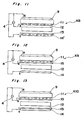
- activation apparatuses K2 to K18 there are shown activation apparatuses K2 to K18 according to second to eighteenth embodiments of the present invention, respectively.
- a plate- like ion inducing electrode, 14 of the activation apparatus Kl is replaced by a comb-shaped ion inducing electrode 14' which has a plurality of long slots 14a extending in its widthwise direction as in the excitation electrode 11.
- the electric field in the treatment space 12 is concentrated to a proper level by the ion inducing electrode 14'.
- the dielectric liner 13 of the activation apparatus K1 is not provided but a dielectric liner 15 is so provided as to be disposed between the article 8 and the excitation electrode 11 such that an electrode surface of the excitation electrode 11 is covered by the dielectric liner 15.
- a dielectric liner 15 is so provided as to be disposed between the article 8 and the excitation electrode 11 such that an electrode surface of the excitation electrode 11 is covered by the dielectric liner 15.
- both the dielectric liner 13 of the activation apparatus Kl and the dielectric liner 15 of the activation apparatus K3 are employed.
- the platelike ion inducing electrode 14 in the activation apparatus K3 of Fig. 6 is replaced by the comb-shaped ion inducing electrode 14' which has a plurality of the long slots 14a extending in its widthwise direction.
- the platelike ion inducing electrode 14 in the activation apparatus K4 of Fig. 7 is replaced by the comb-shaped ion inducing electrode 14' which has a plurality of the long slots 14a extending in its widthwise direction.
- the high-voltage AC power source 4 is connected to the opposite electrode 9 and the excitation electrode 11 and the high-voltage DC power source 7 is connected to the excitation electrode 11 and the ion inducing electrode 14 or 14' in the same manner as in the activation apparatus Kl.
- the AC power source 4 and the DC power source 7 of the activation apparatuses K 2 to K6 can also be modified variously as shown in Figs. 4a to 4h in the same manner as in the activation apparatus Kl.
- the DC power source 7 for impressing the high DC voltage between the excitation electrode 11 and the ion inducing electrode 14 or 14' is eliminated such that the AC power source 4 impresses the high AC voltage also between the excitation electrode 11 and the ion inducing electrode 14 or 14'.
- Other constructions of the activation apparatuses K7 to K12 correspond to those of. the activation apparatuses K1 to K6, respectively.
- the activation apparatus K13 of Fig. 16 is obtained by additionally providing another dielectric member 16, another platelike opposite electrode 17 and another high-voltage AC power source 4b for impressing a high AC voltage between the ion inducing electrode 14' and the opposite electrode 17 in the activation apparatus K2 of Fig. 5.
- the dielectric member 16 is disposed on a surface of the ion inducing electrode 14' remote from the treatment space 12 such that the dielectric member 16 is interposed between the ion inducing electrode 14' and the opposite electrode 17.
- the AC power source 4b is connected, at the terminal c and a terminal d, to the ion inducing electrode 14' and the opposite electrode 17, respectively.
- the article 8 is activated, also on a surface thereof confronting the ion inducing electrode 14', by the positive ions in the plasma creeping along the surface of the ion inducing electrode 14'. Meanwhile, negative ions in the plasma creeping along the surface of the excitation electrode 11 proceed towards the ion inducing electrode 14'. Accordingly, the article 8 inserted into the treatment space 12 is activated, on opposite surfaces thereof, by the negative ions in the plasma creeping along the surface of the excitation electrode 11 and the positive ions in the plasma creeping along the surface of the ion inducing electrode 14', respectively.
- the dielectric liner 13 in order to impart highly efficiently the positive ions of the plasma creeping along the surface of the ion inducing electrode 14', to the surface of the article 8 confronting the ion inducing electrode 14', it is desirable to decrease thickness of the dielectric liner 13 as much as possible. For example, to this end, it can also be so arranged that the dielectric liner 13 is replaced by dielectric material coated thinly on the surface of the ion inducing electrode 14'.
- the activation apparatus K14 of Fig. 17 is obtained by additionally providing the dielectric liner 15 in the activation apparatus K13 such that the dielectric liner 15 is disposed between the excitation electrode 11 and the article 8 inserted into the treatment space 12. Since the electrode surface of the excitation electrode 11 is covered by the dielectric liner 15, such an undesirable phenomenon is prevented that conductive fine particles generated from the surface of the excitation electrode 11 due to electric discharge or mechanical wear thereof adhere to or penetrate into the article 8. In order to prevent the dielectric liner 15 from excessively reducing intensity of the electric field in the treatment space 12, it is desirable to minimize thickness of the dielectric liner 15.
- the dielectric liner 15 is replaced by dielectric material coated thinly..on the surface of the excitation electrode 11.
- this activation apparatus K14 since gas is excited also along a surface of the ion inducing electrode 14' confronting the treatment space 12, plasma creeping along the surface of the ion inducing electrode 14' is produced in the same manner as in the activation apparatus K13.
- the article 8 is activated, also on a surface thereof confronting the ion inducing electrode 14', by positive ions in the plasma creeping along the surface of the ion inducing electrode 14'.
- the activation apparatuses K15 and K16 illustrated in Figs. 18 and 19, respectively are obtained by eliminating the high-voltage AC power source 4b from the activation apparatuses K13 and K14, respectively such that the AC power source 4 acts also as the AC power source 4b.
- the excitation electrode 11 and the opposite electrode 17 are connected to each other and, at the same time, the ion inducing electrode 14' and the opposite electrode 9 are connected to each other.
- the AC power source 4 and the DC power source 7 of the activation apparatuses K15 and K16 can also be modified variously as shown in Figs. 4a to 4h.
- the activation apparatuses K17 and K18 illustrated in Figs. 20 and 21, respectively are obtained by eliminating the high-voltage DC power source 7 from the activation apparatuses K15 and K16, respectively such that the AC power source 4 impresses the high AC voltage also between the excitation electrode 11 and the ion inducing electrode 14'.
- the excitation electrode 11 and the opposite electrode 17 are connected to each other via the AC power source 4.
- an electric field synchronous with the AC power source 4 is formed in the treatment space 12, an ion irradiation rate from the excitation electrode 11 rises.
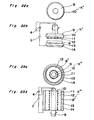
- FIGs. 22 and 23 there are shown cylindrical activation apparatuses K' and K" which are first and second modifications of the present invention, respectively.
- the activation apparatuses K' and K" are rotated relative to the article 8. More specifically, the activation apparatus K' confronting axially the article 8 is rotated relative to the article 8 about an axis,extending at right angles to the opposite surfaces of the article 8, while the activation apparatus K" confronting radially an annular article 8' is rotated relative to and coaxially with the article 8'.
- the excitation electrode 11 and the ion inducing electrode 14' are, respectively, formed with a plurality of the slots lla extending in the widthwise direction and a plurality of the slots 14a extending in the widthwise direction.
- the electric field in the treatment space 12 is preferably concentrated to a proper level.
- the excitation electrode and the ion inducing electrode are each formed into a strip or a plate constituted by a plurality of strips and having a plurality of elongated slots formed between adjacent ones of the strips or a plate formed with a plurality of slits or a brushlike member.
- the excitation electrode is not necessarily required to be formed with a plurality of the slots.
- the excitation electrode and the opposite electrode are made of electrically conductive material such as metals, for example, tungsten, aluminium, steel, stainless steel, brass, copper, carbon, etc.
- the dielectric member and the dielectric liner are made of, for example, rubber, glass, ceramics, plastics (e.g., epoxy resin, polyimide nylon and fluorine plastics such as 2-vinylidene fluoride 4-ethylene fluoride 6-propylene fluoride copolymer, 4-ethylene fluoride perfluoroalkoxy copolymer resin, etc), enamel, asbestos, marble, slate, mica, etc.
- the activation apparatus comprises the dielectric liner which is disposed between the article and at least one of the excitation electrode and the ion inducing electrode so as to cover the electrode surface of the one of the excitation electrode and the ion inducing electrode.
- the dielectric liner is disposed between the ion inducing electrode and the article, it becomes possible to prevent local concentration of activation of the article, with consequent uniform activation of the overall surface of the article.
- the dielectric liner.. is disposed, in the space for receiving the article, between the article and at least one of the electrodes defining the space for receiving the article so as to cover the electrode surface of the one of the electrodes, the article is activated on the surface to a desired level.
- an activation method according to the present invention will be described.
- the present inventors considered an activation method utilizing plasma to be most convenient and effective and examined its applications variously.
- activated articles have excellent performance but activation is required to be performed at subsatmospheric pressure of, for example, not more than 5 mmHg.
- the activation method utilizing plasma at subatmospheric pressure has such an inconvenience that in the case where a large molded item or a long article or a large amount of powder is activated, an activation apparatus therefor becomes large in size or requires a complicated mechanism due to the need for sealing the activation apparatus.
- the activation method of activating a surface of an article comprises the steps of: impressing a high voltage between an excitation electrode and an opposite electrode so as to effect electric discharge therebetween such that the electric discharge forms an electric discharge region; feeding gas to the electric discharge region so as to convert the gas into plasma; and injecting the plasma over the article.
- the excitation electrode and the opposite electrode are made of electrically conductive material such as metals and are not specifically restricted in shape.
- the excitation electrode and the opposite electrode interpose a dielectric member therebetween, it is desirable that the excitation electrode is formed with a plurality of slits or is formed into a coiled shape, an annular shape, etc. so as to expose the dielectric member outwardly such that plasma creeping along a surface of the excitation electrode is produced.
- a power source for impressing a high voltage between the excitation electrode and the opposite electrode outputs generally a voltage of 10 to 50 kV or more preferably of 10 to 30 kV having a frequency of 1 to 100 kHz.
- the output of the power source should be selected properly in accordance with activation purposes.
- a known power source circuit can be employed for the activation method of the present invention.
- discharge current for producing plasma can be controlled to an arbitrary value in accordance with load conditions and that frequency and output of the high-voltage power source can be adjusted to an optimum level.
- a time period during which the power source outputs the high voltage is set at an arbitrary value through presetting of a timer such that an activation time period can be controlled to a predetermined value.
- the gas fed to the electric discharge region includes one of or two or more of, for example, air, nitrogen, oxygen, carbon dioxide, carbon monoxide, ammonia, nitrogen oxide, carbon halide, hydrocarbon halide, vinyl compounds, argon, helium, etc. in accordance with activation purposes.
- gases are generally used at atmospheric pressure or at slightly subatmospheric pressure but can also be used at subatmospheric pressure or at super-atmospheric pressure. It is possible to properly select temperature of the gases. In view of operational convenience and production efficiency, it is most preferable to employ air held at ordinary temperature and pressure.
- a pump, a blower or the like is employed for feeding the gas to the electric discharge region.
- a pump, a blower or the like is employed or it is also possible to use an inertia force of the gas fed to the electric discharge region.
- a passage for the gas is provided, operational efficiency of the activation apparatus improves desirably.
- the gas passage is not specifically restricted in shape and can be formed into, for example, a tubular shape having a circular, elliptic or polygonal cross section or a boxlike shape.
- the gas passage may be formed by only the excitation electrode and the opposite electrode but can also be formed by the excitation electrode, the opposite electrode and the dielectric member disposed between the excitation electrode and the opposite electrode.
- such an arrangement can be employed in which the dielectric member of a tubular or boxlike shape has the excitation electrode and the opposite electrode provided on its inner and outer peripheral surfaces, respectively. Furthermore, it can also be so arranged that the gas passage is formed separately from the electrodes so as to surround the electrodes as in the case where the electric discharge region of the electrodes is provided adjacent to the axis of the tubular shape defining the gas passage.
- the dielectric member of a tubular or boxlike shape has the excitation electrode and the opposite electrode provided on its inner and outer peripheral surfaces, respectively and the excitation electrode confronts, via a space, an ion inducing electrode such that the excitation electrode and the ion inducing electrode are connected to a high-voltage power source.
- the ion inducing electrode is provided, at one side remote from the excitation electrode, with a further opposite electrode through a further dielectric member such that the ion inducing electrode and the further opposite electrode are connected to a high-voltage power source.
- the articles to be treated include plastic products, fibrous products, molded items made of paper, wood, metal or the like, powdery items such as metal powder, metallic oxide powder, pigment or the like, etc. but are not restricted to the above described items.
- activation purposes of the activation method of the present invention include improvement of such characteristics of the molded items as surface adhesive property, coating property, bonding property, wettability, durability or the like and improvement of such characteristics of the powdery items as wettability, dispersion property or the like but are not restricted to these improvements.
- Feed rate of the gas and injection speed of the active gas can be properly selected in accordance with impressed voltage, frequency, kinds of the article, etc. Meanwhile, activation time period can also be selected properly based on impressed voltage, frequency, kinds of the article, feed rate of the gas, injection speed of the active gas, activation purposes, etc.
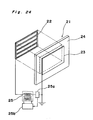
- the first activation apparatus S1 includes a pair of electrode units 21.
- the electrode unit 21 includes an excitation electrode 22, a sheetlike opposite electrode 23 and a sheetlike dielectric member 24 disposed between the excitation electrode 22 and the opposite electrode 23.
- a high voltage power source 25 is connected between the excitation electrode 22 and the opposite electrode 23.
- the high-voltage power source 25 is provided with a sensor 25a for detecting current intensity and voltage and a control device 25b for controlling the high-voltage power source 25.
- detection signals outputted from the sensor 25a are fed back to the control device 25b such that the high-voltage power source 25 can be arbitrarily set at optimum current intensity and voltage outputs in accordance with load conditions.
- the excitation electrode 22 has a latticed shape such that the dielectric member 24 is exposed outwardly. Meanwhile, the opposite electrode 23 is grounded.
- the first activation apparatus S1 includes a boxlike member 26 in which a gas passage is defined.
- the boxlike member 26 has a pair of the electrode units 21 acting as one pair of opposite side walls thereof, respectively such that the excitation electrodes 22 of the respective electrode units 21 confront each other in the boxlike member 26 as best shown in Fig. 26a.
- the boxlike member 26 is formed, at its top wall 27, with a gas inlet 28 and a pipe 29 for conveying gas supplied from a blower (not shown) is connected with the gas inlet 8.
- a bottom portion of the boxlike member 26 is open so as to act as an injection port 30.
- the other pair of opposite side walls of the boxlike member 26 are formed by other dielectric members as shown in Fig. 26b but can be replaced by the electrode units 21 or the like.
- the gas drawn into the boxlike member 26 from the gas inlet 28 is activated while flowing through an electric discharge region and then, is injected over a platelike article 31 from the injection port 30 so as to activate the surface of the article 31.
- the arrows in Figs. 25, 26a and 26b indicate directions of flow of the gas.
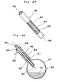
- the second activation apparatus S2 includes a tubular electrode unit 41.
- the electrode unit 41 includes an annular dielectric member 44, a coiled excitation electrode 42 disposed inside the dielectric member 44 and a netted opposite electrode 43 surrounding the dielectric member 44 such that the dielectric member 44 is interposed between the excitation electrode 42 and the opposite electrode 43.
- a high-voltage power source (not shown) is connected between the excitation electrode 42 and the opposite electrode 43.
- the electrode unit 41 has a gas inlet 45 and an injection port 46 formed at opposite open ends thereof, respectively.
- the second activation apparatus S2 further includes a round flask 47 for containing powder material 51 to be treated.
- the electrode unit 41 is inserted into a neck 48 of the round flask 47 in its axial direction.
- One end of the dielectric member 44 of the electrode unit 41 projects out of a distal end of the neck 48 of the round flask 47 so as to be connected with a blower (not shown).
- the neck 48 has an exhaust port 49 formed at a side portion thereof.
- a gas passage is defined between the neck 28 and the electrode unit 21 so as to be communicated with the exhaust port 49 via a filter 50.
- the powder material 51 is accommodated in the round flask 47.
- Gas conveyed from the blower is drawn from the gas inlet 45 into an electric discharge portion formed inside the electrode unit 41.
- the gas is converted into active gas at the electric discharge portion.
- the active gas is injected from the injection port 46 over the powder material 51 so as to activate the powder material 51 through agitation thereof and then, is discharged, by way of the filter 50, out of the exhaust port 49.
- the round flask 47 is arranged to be rotated about the axis of the neck 48 by a motor through a belt, while the electrode unit 41 is fixedly supported so as not to be rotated together with the rotating round flask 47.
- the arrows in Fig. 28 indicate directions of flow of the gas.
- the activation apparatus for carrying out the activation method of the present invention is not restricted to those S1 and S2 but the aforesaid activation apparatuses Kl to K18, K' and K" can also be employed therefor.
- the activation apparatus S3 has a plurality of axially extending cylindrical gas passages each defined by the cylindrical excitation electrode 22.
- the activation apparatus S3 axially confronts the article 31 and is rotated relative to the article 31 about an axis extending at right angles to the opposite surfaces of the article 31.
- the activation apparatus S4 has a plurality of radially extending cylindrical gas passages each defined by the cylindrical excitation electrode 22.
- An annular article 31' is rotated relative to and coaxially with the activation apparatus S4.
- the dielectric member 24 is made of ceramics and has a thickness of 0.5 mm so as to be provided, at opposite surfaces thereof, with the excitation electrode 22 and the opposite electrode 23.
- a pair of the electrode units 21 of the above described arrangement are assembled into the first activation apparatus S1 of Fig. 25 such that dimensions A and B in Figs. 26a and 26b assume 5 mm and 13 cm, respectively.
- a sheet made of polypropylene was surface treated by using this first activation apparatus S1. By setting a distance C (Figs.
- a voltage of 25 kV having a frequency of 5 kHz is impressed between the excitation electrode 22 and the opposite electrode 23 so as to effect electric discharge under atmosphere of air such that active gas generated by the electric discharge is injected over the polypropylene sheet, whereby the polypropylene sheet was surface treated.
- Quinacridone pigment was surface treated by using the activation apparatus S2 of Fig. 28. 30 parts by weight of the quinacridone pigment is put into the round flask 47 and then, the round flask 47 is rotated at 30 rpm. A voltage of 25 kV having a frequency of 5 kHz is impressed to the electrode unit 41 and air is drawn from the gas inlet 45 into the electrode unit 41 so as to effect electric discharge under atmosphere of air such that active gas generated by the electric discharge is injected over the quinacridone pigment, whereby the quinacridone pigment was surface treated.
- the high voltage is impressed between the excitation electrode and the opposite electrode so as to effect electric discharge therebetween such that the electric discharge defines the electric discharge region.
- gas is fed to the electric discharge region so as to generate active gas such that the active gas is injected over the article.
Landscapes
- Physics & Mathematics (AREA)
- Engineering & Computer Science (AREA)
- Plasma & Fusion (AREA)
- Physical Or Chemical Processes And Apparatus (AREA)
- Electron Sources, Ion Sources (AREA)
Applications Claiming Priority (4)
| Application Number | Priority Date | Filing Date | Title |
|---|---|---|---|
| JP217000/84 | 1984-10-15 | ||
| JP21700084A JPS6193829A (ja) | 1984-10-15 | 1984-10-15 | 活性化装置 |
| JP23773584A JPS61118136A (ja) | 1984-11-12 | 1984-11-12 | 表面処理法 |
| JP237735/84 | 1984-11-12 |
Publications (2)
| Publication Number | Publication Date |
|---|---|
| EP0178907A2 true EP0178907A2 (de) | 1986-04-23 |
| EP0178907A3 EP0178907A3 (de) | 1987-06-16 |
Family
ID=26521756
Family Applications (1)
| Application Number | Title | Priority Date | Filing Date |
|---|---|---|---|
| EP85307422A Withdrawn EP0178907A3 (de) | 1984-10-15 | 1985-10-15 | Verfahren und Vorrichtung zur Aktivierung |
Country Status (3)
| Country | Link |
|---|---|
| EP (1) | EP0178907A3 (de) |
| AU (2) | AU582590B2 (de) |
| CA (1) | CA1276908C (de) |
Cited By (12)
| Publication number | Priority date | Publication date | Assignee | Title |
|---|---|---|---|---|
| GB2259185A (en) * | 1991-08-20 | 1993-03-03 | Bridgestone Corp | Method and apparatus for surface treatment |
| US5272414A (en) * | 1990-05-08 | 1993-12-21 | I.T.M. Corporation | Discharge element, method of producing the same and apparatus comprising the same |
| US5385761A (en) * | 1990-05-08 | 1995-01-31 | I.T.M. Corporation | Discharge element, method of producing the same and apparatus comprising the same |
| EP0908728A3 (de) * | 1997-09-16 | 2001-05-23 | bioMerieux Vitek, Inc. | Strukturierte Oberfläche für Testkarte für Analysen und Giessform zur Herstellung derselben |
| WO2001039944A1 (de) * | 1999-12-01 | 2001-06-07 | Vioel Wolfgang | Verfahren zur modifizierung von holzoberflächen durch elektrische entladung unter atmosphärendruck |
| EP1293216A4 (de) * | 2000-05-18 | 2003-08-20 | Sharp Kk | Verfahren zur sterilisation, ionenerzeugendes element, ionen erzeugende vorrichtung und klimaanlage |
| EP1483064A4 (de) * | 2002-02-14 | 2005-11-09 | Sheree H Wen | Infektvorbeugende und toxinbeseitigende vorrichtung |
| EP2127753A1 (de) * | 2003-05-15 | 2009-12-02 | Sharp Kabushiki Kaisha | Ionerzeugungselement und Ionerzeugungsvorrichtung, die mit diesem Element ausgestattet ist |
| CN100579585C (zh) | 2000-05-18 | 2010-01-13 | 夏普公司 | 杀菌方法、离子发生元件、离子发生装置和空气调节装置 |
| CN101621181B (zh) * | 2003-05-15 | 2012-09-12 | 夏普株式会社 | 离子发生元件、离子发生装置、电气设备 |
| EP3806586A4 (de) * | 2018-05-30 | 2022-01-12 | Toshiba Mitsubishi-Electric Industrial Systems Corporation | Aktivgaserzeugungsvorrichtung |
| EP3886540A4 (de) * | 2019-11-27 | 2022-07-06 | Toshiba Mitsubishi-Electric Industrial Systems Corporation | Aktivgaserzeugungsvorrichtung |
Family Cites Families (5)
| Publication number | Priority date | Publication date | Assignee | Title |
|---|---|---|---|---|
| US3779882A (en) * | 1971-04-01 | 1973-12-18 | Union Carbide Corp | Electrode method for the surface treatment of thermoplastic materials |
| US4159425A (en) * | 1973-08-13 | 1979-06-26 | Union Carbide Corporation | Corona reaction system |
| US4155093A (en) * | 1977-08-12 | 1979-05-15 | Dennison Manufacturing Company | Method and apparatus for generating charged particles |
| NZ192629A (en) * | 1979-02-05 | 1983-05-31 | British Cellophane Ltd | Treating plastics film by corona discharge electrodes constructed and spaced to prevent arc discharges |
| US4275301A (en) * | 1980-03-10 | 1981-06-23 | Armstrong Cork Company | Corona discharge device |
-
1985
- 1985-10-15 CA CA000492963A patent/CA1276908C/en not_active Expired - Lifetime
- 1985-10-15 AU AU48595/85A patent/AU582590B2/en not_active Ceased
- 1985-10-15 EP EP85307422A patent/EP0178907A3/de not_active Withdrawn
-
1988
- 1988-06-30 AU AU18567/88A patent/AU601856B2/en not_active Ceased
Cited By (25)
| Publication number | Priority date | Publication date | Assignee | Title |
|---|---|---|---|---|
| US5272414A (en) * | 1990-05-08 | 1993-12-21 | I.T.M. Corporation | Discharge element, method of producing the same and apparatus comprising the same |
| US5385761A (en) * | 1990-05-08 | 1995-01-31 | I.T.M. Corporation | Discharge element, method of producing the same and apparatus comprising the same |
| GB2259185A (en) * | 1991-08-20 | 1993-03-03 | Bridgestone Corp | Method and apparatus for surface treatment |
| US5316739A (en) * | 1991-08-20 | 1994-05-31 | Bridgestone Corporation | Method and apparatus for surface treatment |
| GB2259185B (en) * | 1991-08-20 | 1995-08-16 | Bridgestone Corp | Method and apparatus for surface treatment |
| EP0908728A3 (de) * | 1997-09-16 | 2001-05-23 | bioMerieux Vitek, Inc. | Strukturierte Oberfläche für Testkarte für Analysen und Giessform zur Herstellung derselben |
| US6267929B1 (en) | 1997-09-16 | 2001-07-31 | BIO MéRIEUX, INC. | Textured surface for test sample cards |
| EP1867393A3 (de) * | 1997-09-16 | 2011-03-02 | bioMerieux Vitek, Inc. | Strukturierte Oberfläche für eine Testkarte für Analysen und Gießform zur Herstellung derselben |
| WO2001039944A1 (de) * | 1999-12-01 | 2001-06-07 | Vioel Wolfgang | Verfahren zur modifizierung von holzoberflächen durch elektrische entladung unter atmosphärendruck |
| US6818102B1 (en) | 1999-12-01 | 2004-11-16 | Wolfgang Viol | Method for modifying wooden surfaces by electrical discharges at atmospheric pressure |
| CZ297731B6 (cs) * | 1999-12-01 | 2007-03-14 | Zpusob modifikování povrchu dreva | |
| EP1681066A1 (de) * | 2000-05-18 | 2006-07-19 | Sharp Kabushiki Kaisha | Verfahren zum Sterilisieren, Vorrichtung zur Erzeugung von Ionen und Luftaufbereitungsvorrichtung |
| US7854900B2 (en) | 2000-05-18 | 2010-12-21 | Sharp Kabushiki Kaisha | Sterilization method |
| AU781782B2 (en) * | 2000-05-18 | 2005-06-16 | Sharp Kabushiki Kaisha | Sterilization method, ion generating element, ion generating device, and air conditioning device |
| EP2033664A1 (de) * | 2000-05-18 | 2009-03-11 | Sharp Kabushiki Kaisha | Sterilisationsverfahren, ionenerzeugendes Element, ionenerzeugendes Gerät und Klimaanlage |
| EP1293216A4 (de) * | 2000-05-18 | 2003-08-20 | Sharp Kk | Verfahren zur sterilisation, ionenerzeugendes element, ionen erzeugende vorrichtung und klimaanlage |
| CN100579585C (zh) | 2000-05-18 | 2010-01-13 | 夏普公司 | 杀菌方法、离子发生元件、离子发生装置和空气调节装置 |
| EP1483064A4 (de) * | 2002-02-14 | 2005-11-09 | Sheree H Wen | Infektvorbeugende und toxinbeseitigende vorrichtung |
| EP2127753A1 (de) * | 2003-05-15 | 2009-12-02 | Sharp Kabushiki Kaisha | Ionerzeugungselement und Ionerzeugungsvorrichtung, die mit diesem Element ausgestattet ist |
| EP2127754A1 (de) * | 2003-05-15 | 2009-12-02 | Sharp Kabushiki Kaisha | Ionerzeugungsvorrichtung |
| US7916445B2 (en) | 2003-05-15 | 2011-03-29 | Sharp Kabushiki Kaisha | Ion generating apparatus |
| US7961451B2 (en) | 2003-05-15 | 2011-06-14 | Sharp Kabushiki Kaisha | Ion generating element, and ion generating apparatus equipped with same |
| CN101621181B (zh) * | 2003-05-15 | 2012-09-12 | 夏普株式会社 | 离子发生元件、离子发生装置、电气设备 |
| EP3806586A4 (de) * | 2018-05-30 | 2022-01-12 | Toshiba Mitsubishi-Electric Industrial Systems Corporation | Aktivgaserzeugungsvorrichtung |
| EP3886540A4 (de) * | 2019-11-27 | 2022-07-06 | Toshiba Mitsubishi-Electric Industrial Systems Corporation | Aktivgaserzeugungsvorrichtung |
Also Published As
| Publication number | Publication date |
|---|---|
| EP0178907A3 (de) | 1987-06-16 |
| AU4859585A (en) | 1986-04-24 |
| CA1276908C (en) | 1990-11-27 |
| AU582590B2 (en) | 1989-04-06 |
| AU1856788A (en) | 1988-10-13 |
| AU601856B2 (en) | 1990-09-20 |
Similar Documents
| Publication | Publication Date | Title |
|---|---|---|
| EP0178907A2 (de) | Verfahren und Vorrichtung zur Aktivierung | |
| Falkenstein et al. | Microdischarge behaviour in the silent discharge of nitrogen-oxygen and water-air mixtures | |
| EP0109334A2 (de) | Verfahren um einem geformten Kunststoffkörper verbesserte Oberflächeneigenschaften zu verleihen | |
| US4622237A (en) | Method of flame activation of substrates | |
| EP0171239A1 (de) | Vorrichtung und Verfahren zur Oberflächenbehandlung | |
| EP0106194B1 (de) | Verfahren um die Oberflächeneigenschaften eines Formgegenstandes aus einem Polymer zu verbessern | |
| EP0180020A3 (de) | Plasmaätzvorrichtung | |
| JP2003523053A (ja) | 大気圧プラズマシステム | |
| US11040327B2 (en) | Barrel reactor with electrodes | |
| JP2524942B2 (ja) | プラズマ表面処理装置 | |
| JPH04334543A (ja) | 管内大気圧グロープラズマ反応方法とその装置 | |
| Andreev et al. | Use electrodes with high active electrical resistance as a way to increase the productivity of an ozone generator based on dielectric barrier discharge | |
| US5176924A (en) | Apparatus for plasma treatment of interior surfaces of hollow plastic objects | |
| Kang | Decomposition of chlorofluorocarbon by non-thermal plasma | |
| US5215637A (en) | Method for electronic treatment of interior surfaces of hollow plastic objects | |
| JP3577601B2 (ja) | 大気圧グロ−放電プラズマ処理法 | |
| JPH0523579A (ja) | 表面処理方法及びその装置 | |
| Borcia et al. | Atmospheric-pressure dielectric barrier discharge for surface processing of polymer films and fibers | |
| JPS6424835A (en) | Discharge process and apparatus for modifying surface of solid | |
| SU707676A1 (ru) | Колонка дл активации св зующих веществ | |
| SU494685A1 (ru) | Способ определени рассеивающей способности покрытий в процессе электроосаждени | |
| JPS61118136A (ja) | 表面処理法 | |
| SU980672A2 (ru) | Устройство дл разм гчени м са | |
| JP3699832B2 (ja) | 多孔質体の放電処理方法 | |
| SU1423877A1 (ru) | Способ сушки материалов |
Legal Events
| Date | Code | Title | Description |
|---|---|---|---|
| PUAI | Public reference made under article 153(3) epc to a published international application that has entered the european phase |
Free format text: ORIGINAL CODE: 0009012 |
|
| AK | Designated contracting states |
Kind code of ref document: A2 Designated state(s): DE FR GB IT |
|
| RAP1 | Party data changed (applicant data changed or rights of an application transferred) |
Owner name: SANKYO DENGYO CO., LTD. Owner name: NIPPON PAINT CO., LTD. |
|
| PUAL | Search report despatched |
Free format text: ORIGINAL CODE: 0009013 |
|
| AK | Designated contracting states |
Kind code of ref document: A3 Designated state(s): DE FR GB IT |
|
| RAP1 | Party data changed (applicant data changed or rights of an application transferred) |
Owner name: NIPPON PAINT CO., LTD. |
|
| STAA | Information on the status of an ep patent application or granted ep patent |
Free format text: STATUS: THE APPLICATION IS DEEMED TO BE WITHDRAWN |
|
| 18D | Application deemed to be withdrawn |
Effective date: 19871217 |
|
| RIN1 | Information on inventor provided before grant (corrected) |
Inventor name: TSUTSUI, KOICHI Inventor name: SAITOH, TOSHIYUKI Inventor name: INAGAKI, TSUGUYA Inventor name: IKEDA, SHOJI |