EP0181729B1 - Vorrichtung zur Prüfung von Schaltungsplatten - Google Patents
Vorrichtung zur Prüfung von Schaltungsplatten Download PDFInfo
- Publication number
- EP0181729B1 EP0181729B1 EP85307793A EP85307793A EP0181729B1 EP 0181729 B1 EP0181729 B1 EP 0181729B1 EP 85307793 A EP85307793 A EP 85307793A EP 85307793 A EP85307793 A EP 85307793A EP 0181729 B1 EP0181729 B1 EP 0181729B1
- Authority
- EP
- European Patent Office
- Prior art keywords
- cart
- test chamber
- baskets
- electrical connectors
- circuit boards
- Prior art date
- Legal status (The legal status is an assumption and is not a legal conclusion. Google has not performed a legal analysis and makes no representation as to the accuracy of the status listed.)
- Expired
Links
- 238000012360 testing method Methods 0.000 title claims abstract description 102
- 238000010276 construction Methods 0.000 claims description 6
- 238000004378 air conditioning Methods 0.000 description 8
- 230000001143 conditioned effect Effects 0.000 description 5
- 230000007613 environmental effect Effects 0.000 description 2
- 238000001816 cooling Methods 0.000 description 1
- 238000010438 heat treatment Methods 0.000 description 1
- 238000004064 recycling Methods 0.000 description 1
- 238000010998 test method Methods 0.000 description 1
Images


Classifications
-
- G—PHYSICS
- G01—MEASURING; TESTING
- G01R—MEASURING ELECTRIC VARIABLES; MEASURING MAGNETIC VARIABLES
- G01R1/00—Details of instruments or arrangements of the types included in groups G01R5/00 - G01R13/00 and G01R31/00
- G01R1/02—General constructional details
- G01R1/04—Housings; Supporting members; Arrangements of terminals
-
- G—PHYSICS
- G01—MEASURING; TESTING
- G01R—MEASURING ELECTRIC VARIABLES; MEASURING MAGNETIC VARIABLES
- G01R31/00—Arrangements for testing electric properties; Arrangements for locating electric faults; Arrangements for electrical testing characterised by what is being tested not provided for elsewhere
- G01R31/28—Testing of electronic circuits, e.g. by signal tracer
- G01R31/2801—Testing of printed circuits, backplanes, motherboards, hybrid circuits or carriers for multichip packages [MCP]
- G01R31/281—Specific types of tests or tests for a specific type of fault, e.g. thermal mapping, shorts testing
- G01R31/2817—Environmental-, stress-, or burn-in tests
Definitions
- the invention relates to apparatus for use in testing electrical apparatus such as circuit boards, and, more particularly, to apparatus for use in "burning in” electrical circuit boards.
- Burning in is commonly done in a test chamber wherein the circuit boards are subjected to varying environmental conditions while being plugged into an electrical control system for putting the circuit boards through their operational cycles.
- a burn-in test chamber is disclosed in US-A--4374317.
- EP-A-0105151 and US-A-4179724 each disclose arrangements for mounting in parallel a plurality of circuit boards in a carrying frame or box so that electrical connectors in the boards engage connectors supported by the frame or box to facilitate connection of the boards to further components or connectors, but neither is concerned with such arrangements for use in conjunction with a test chamber for a burn-in operation.
- a hand manipulable basket for containing a plurality of generally planar circuit boards, said basket having frame means defining a structure of generally open construction, a plurality of first electrical connectors supported by said frame means and being adapted to engage electrical connectors on the circuit boards, and means for supporting the circuit boards in parallel spaced relationship within said frame means with the electrical connectors on the circuit boards being plugged into said first electrical connectors, characterized in that the basket further has a second electrical connector supported by said frame means and being electrically connected with each of said first electrical connectors and adapted to be plugged into a test chamber, and in that the basket, when inserted in the test chamber, cooperates with wall means of the test chamber to define an air plenum directing air flow through said basket and over the circuit boards supported therein.
- Such baskets provide a convenient means for handling the circuit boards in connection with the burn-in operation. They also provide a convenient means for transporting the circuit boards between the burning in station and other test stations. Furthermore, the baskets, in a single structure, provide both the support structure for the circuit boards and the electrical circuitry for accessing the circuit boards for test purposes, and in the test chamber ensure that air can flow freely over the boards under test.
- the baskets which preferably have the second electrical connector disposed at one end, may be inserted individually into the test chamber such that the second electrical connectors on the baskets engage electrical connectors on the rear wall of the test chamber.
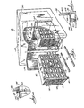
- the drawings illustrate a test chamber 10 for use in testing or burning in electrical circuit boards.
- the test chamber 10 receives hand manipulable baskets 12 adapated to contain a plurality of circuit boards 14.
- a circuit board 14 is shown in Fig. 15.
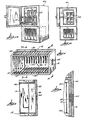
- a basket 12 is illustrated in Fig. 2.
- the basket 12 has a frame defining a box-like structure of generally open construction.
- the opposite ends of the basket 12 are closed by end walls 16 and 18, and one of the sides of the basket 12 is closed by a side wall 20.
- the other three sides of the basket 12 are open.
- a handle 22 (see Fig. 6) is attached to the outside of the end wall 18 for facilitating hand manipulation of the basket 12.
- a plurality of generally evenly spaced apart electrical connectors 24 are mounted inside the side wall 20 of the basket 12 and are adapted to receive electrical connectors 26 (see Fig. 15) on the electrical circuit boards 14.
- the electrical connectors 24 are female connectors, and the connectors 26 on the circuit boards 14 are male connectors.
- Basket 12 also includes, on the outer surface of the end wall 16, a second electrical connector 28 adapted to be plugged into a test chamber.
- the electrical connector 28 is electrically connected to each of the electrical connectors 24 by electrical circuitry (indicated by the dotted line in Fig. 2) extending along the side wall 20 and the end wall 16. This circuitry is similar to the circuitry shown in Fig. 16 on a hereinafter described cart 32.
- the test chamber is operably connected to each of the circuit boards 14 in the basket 12 by way of the electrical connectors 24.
- the basket 12 also includes means for supporting the circuit boards 14 in parallel spaced relationship within the frame means with the electrical connectors 26 on the circuit boards 14 received in electrical connectors 24 in the basket 12, as shown in Figs. 2 and 3.
- the supporting means consists solely of electrical connectors 24.
- supporting means in addition to electrical connectors 24 is provided so that the basket 12 can hold heavier circuit boards 14.
- the supporting means includes a plurality of spaced apart guide tracks 30 fixedly attached to the frame means and extending across opposite open sides.
- the guide tracks 30 are aligned with the electrical connectors 24 for guiding the electrical connectors 26 on the circuit boards 14 into engagement with electrical connectors 24.
- Each of the guide tracks 30 includes a channel shaped, elongated member adapted to slidably receive an edge of a circuit board 14.
- the baskets 12 provide a convenient means for housing and supporting circuit boards 14 for burning in, as well as for transporting the circuit boards 14 to and from other various testing stations. Furthermore, the baskets 12 include, in one unit, both the electrical circuitry and the support structure for the circuit boards 14.
- the test chamber 10 in the preferred embodiment also accommodates carts 32 adapted to contain a plurality of the baskets 12.
- a cart 32 is illustrated in Fig. 5 and includes opposite open ends 33 and 35, respectively, and one open side between the open ends.
- a side wall 34 closes the side opposite the open side, and top and bottom walls 36 and 38, respectively, close the top and bottom of the cart 32.
- the cart 32 is supported by casters 40 connected to the bottom wall 38, as best shown in Figure 4.
- the cart 32 includes wall means cooperating with the baskets 12, when positioned in the cart, to define an air plenum directing air flow through the baskets 12 contained in the cart 32 and over the circuit boards 14 supported in the baskets.
- the side wall 34 and the top and bottom walls 36 and 38 are the wall means.
- the cart 32 also includes a plurality of electrical connectors 42 mounted inside the side wall 34 of the cart 32 and adapted to engage the electrical connectors 28 on the ends of the baskets 12.
- the cart 32 includes framework 44 for slidably receiving a plurality of baskets 12.
- the baskets 12 are insertable into the framework 44 such that the second electrical connectors 28 on the ends of the baskets 12 engage the electrical connectors 42 inside the side wall 34 of the cart 32, as shown in Fig. 7, and such that the end walls 38 of the baskets 12 close the open side of the cart 32, as best shown in Fig. 1.
- the cart 32 With the baskets 12 inserted into the cart 32, the top and bottom and both sides of the cart 32 are closed, and the opposite ends of the cart 32 are open, so that the cart 32 and baskets 12 define an air plenum through which air flow may be directed to pass over the baskets 12 and the circuit boards 14 in the baskets.
- the baskets 12 are inserted into the cart with the side walls 20 of the baskets 12 facing downwardly, as shown in Fig. 6, so that the closed sides of the baskets 12 in each row are aligned to divide the air plenum into separate horizontal air ducts corresponding with each row of baskets 12.
- the cart 32 also includes electrical connector means 46 in electrical circuit with each of the electrical connectors 42 and adapted to be plugged into a test chamber.
- the electrical connector means 46 includes a main electrical connector 48 on the end 33 of the cart 32.
- the main electrical connector 48 is slidably engageable with an electrical connector in the test chamber and is preferably located near the bottom of the cart 32, as best shown in Figure 10.
- the electrical circuitry connecting the main electrical connector 48 to the electrical connectors 42 includes a plurality of bus bars 50 running along the side wall 34 of the cart 32, with each of the bus bars 50 being connected to the main electrical connector 48 and to each of the electrical connectors 42. This is best shown in Fig. 16.
- the test chamber 10 also includes a housing 52.
- the preferred embodiment of the test chamber 10 is shown in Figure 1. This is a walk-in test chamber adapted to hold two carts 32.
- the housing 52 is enclosed and includes a pair of doors 54 (only, one is shown) in one of the side walls for allowing the carts 32 to be placed within the test chamber 10. When the doors 54 are closed, the test chamber 10 is substantially sealed.
- the test chamber 10 includes an air conditioning unit 56 for varying the temperature and humidity of the air within the test chamber.
- the air conditioning unit 56 includes a pair of airflow openings 58 adapted to register with the open end 33 of a cart 32.
- the airflow openings 58 are air intake openings.
- the air conditioning unit further includes a pair of air outlet openings 60 through which conditioned air is introduced into the test chamber.
- the test chamber 10 also includes electrical connectors 62 (see Figs. 1 and 11) mounted on the wall of the air conditioning unit 56 beneath the air intake openings 58.
- the electrical connectors 62 are adapted to receive the main electrical connectors 48 on the carts 32.
- the electrical connectors 62 are connected to electrical control means (not shown) for operating the circuit boards 14 through the desired test cycle.
- the test chamber also includes, around each of the air intake openings 58, a flexible seal or gasket 64 (see Figs. 1 and 12) for registering with the end 33 of the cart 32 to seal the intake opening 58 to the cart 32.
- the seal 64 may be attached to the cart 32 around the end 33 and registers with the air intake opening 58.
- the test chamber 10 is provided with slots 66 (see Fig. 1) in the floor of the test chamber for receiving the casters 40 on the carts 32 so as to align the carts 32 with the air intake openings 58 and to align the main electrical connectors 48 on the carts 32 with the electrical connectors 62 in the test chamber 10.
- the test chamber 10 may be converted to a walk-in chamber with a level floor and suitable for use without carts 32 by placing bars 68 in the slots 66.
- the test chamber 10 is further provided with interengageable means on the carts 32 and in the test chamber for moving the carts 32 toward the air intake openings 58 with a positive seating force such that the main electrical connectors 48 are moved into engagement with the electrical connectors 62 in the test chamber 10, and such that the ends 33 of the carts 32 are moved into engagement with the seals 64.
- the interengageable means includes recesses 70 in the wall of the test chamber near the bottoms of the air intake openings 58. Horizontal pins 72 in the recesses are parallel to and fixedly attached to the wall. This is best shown in Figs. 8 and 9.
- the interengageable means further includes handles 74 (see Figs. 1, and 9) movably attached to the carts 32, and linkages 76 attached to the handles 74 for engaging the pins 72 and drawing the carts 32 toward the air intake openings 58 in response to movement of the handles 74.
- the handle 74 is pivotally attached to the end 35 of the cart 32.
- the handle 74 facilitates both pushing the cart 32 into the test chamber 10 and pulling the cart 32 out of the test chamber 10.
- the handle 74 includes two generally vertical members 78 pivotally attached to the cart 32 for pivotal movement about a generally horizontal axis 80, and the linkage 76 includes a pair of generally horizontal members 82 (only one is shown), one along each side of the cart and each having an end pivotally attached to the lower end of one of the vertical members 78 of the handle 74.
- the opposite ends of the horizontal members 82 include a hook 84 for engaging one of the horizontal pins 72.
- the hook ends of the horizontal members 82 are extendable and retractable relative to the end 33 of the cart 32 in response to pivotal movement of the handle 74.
- the hook ends of the horizontal members 82 are tapered at 83 to facilitate movement of the hook 84 over the pin 72.
- the handle 74 and the horizontal member 82 also include means for lifting the hook end of the horizontal member 82 over the pin 72.
- this means includes an abutment 86 on the outer surface of the vertical member 74 adapted to engage the upper surface 88 of the horizontal member 82, and an abutment 90 on the inner surface of the horizontal member 82 adapted to engage the forward surface 90 of the vertical member 78.
- the abutments 86 and 90 are positioned such that they do not engage their respective members until the horizontal member 82 is partially extended from the end 33 of the cart 32. Prior to engagement of the members by the abutments 86 and 90, the horizontal member 82 remains in a generally horizontal position, as shown in Fig.
- FIG. 13 An alternative test chamber 100 is illustrated in Figs. 13 and 14.
- the baskets 12 are inserted directly into the test chamber 100 without the carts 32.
- the test chamber 100 includes a rear wall 101 having mounted thereon a plurality of electrical connectors 102 engageable with the electrical connectors 28 on the baskets 12, as shown in Fig. 4.
- the baskets 12 are inserted into the test chamber 100 such that the second electrical connectors 28 engage the electrical connectors 102 on the rear wall, and with the side walls 20 of the baskets 12 facing either side of the test chamber 100.
- the side walls of the test chamber 100, the side walls 20 of the baskets 12, and the end walls 16 and 18 of the baskets 12 cooperate to define a vertical air plenum through which air flow will be directed vertically through the baskets 12 and over the circuit boards 14 supported therein.
- the test chamber 100 also includes means (shown schematically in dotted lines in Fig. 13) for circulating air through the baskets 12.
- the test chamber 10 is used as follows. Circuit boards 14 are transported from an assembly or prior testing station to the burn-in station in the baskets 12. In the illustrated construction, forty baskets 12 are needed to fill the two carts 32. The circuit boards 14 are already plugged into the baskets 12.
- the baskets 12 are inserted into the two carts 32 such that the electrical connectors 28 on the ends of the baskets 12 engage the electrical connectors 42 inside the carts 32.
- the circuit boards 14 inside the baskets 12 are electrically connected into the carts 32.
- the carts 32 are then pushed into the test chamber 10 with the casters 40 on the carts 32 being received in the slots 66 in the floor of the test chamber 10.
- the slots 66 align the carts 32 with the air intake openings 58 and the main electrical connectors 48 on the carts 32 with the electrical connectors 62 in the test chamber 10.
- the handles 74 When the carts 32 near the air intake openings 58, the handles 74 should be pulled away from the ends of the carts 32 so that the hook ends of the horizontal members 82 extend from the opposite ends of the carts 32, and such that the hooks 84 are moved over the horizontal pins 72. In the event that a tight fit between the ends of the carts 32 and the seals 64 or between the main electrical connectors 48 on the carts 32 and the electrical connectors 62 in the test chamber 10 prevents pushing the carts 32 by hand completely into the test chamber 10, the handles 74 can be used to pull the carts 32 into position.
- the hooks 84 engage the horizontal pins 72 and pull the carts 32 toward the air intake openings 58 such that the ends 33 of the carts register with the seals 64 and the air intake openings 58, and such that the electrical connectors 48 on the carts 32 engage tne electrical connectors tj; ⁇ in tne test cnamoer 10.
- the circuit boards 14 are electrically connected to the control means in the test chamber 10 for recycling the circuit boards through the directed test procedure.
- the test chamber doors 54 are closed and the air conditioning unit 56 is turned on.
- the air conditioning unit 56 blows air into the test chamber 10 through the air outlet openings 60.
- this conditioned air is drawn through the open ends 35 of the carts 32 and is into the air conditioning unit 56 through the air intake openings 58.
- the conditioned air passes over all of the circuit boards 14 contained within the carts 32.
- An air circulation path is established so that the conditioned air flows immediately over the circuit boards 14 contained within the carts 32. Therefore, when the air conditioning unit 56 is changed from a hot cycle to a cold cycle, or vice versa, the circuit boards 14 are almost immediately heated or cooled, and time is not wasted heating or cooling the remainder of the test chamber 10.
- the electrical control means puts the circuit boards 14 through their operational cycles.
- the handles 74 may be used to pull the carts 32 out of the test chamber 10.
- the baskets 12 are then removed from the carts 32 and may be used to transport the circuit boards 14 to the next station for further processing.
Landscapes
- Engineering & Computer Science (AREA)
- Physics & Mathematics (AREA)
- General Physics & Mathematics (AREA)
- Computer Hardware Design (AREA)
- Microelectronics & Electronic Packaging (AREA)
- General Engineering & Computer Science (AREA)
- Testing Of Individual Semiconductor Devices (AREA)
- Compositions Of Macromolecular Compounds (AREA)
- Monitoring And Testing Of Exchanges (AREA)
- Tests Of Electronic Circuits (AREA)
- Testing Electric Properties And Detecting Electric Faults (AREA)
- Printing Elements For Providing Electric Connections Between Printed Circuits (AREA)
Claims (11)
Priority Applications (1)
| Application Number | Priority Date | Filing Date | Title |
|---|---|---|---|
| AT85307793T ATE48931T1 (de) | 1984-11-07 | 1985-10-29 | Vorrichtung zur pruefung von schaltungsplatten. |
Applications Claiming Priority (2)
| Application Number | Priority Date | Filing Date | Title |
|---|---|---|---|
| US669117 | 1984-11-07 | ||
| US06/669,117 US4683424A (en) | 1984-11-07 | 1984-11-07 | Apparatus for use in testing circuit boards |
Publications (2)
| Publication Number | Publication Date |
|---|---|
| EP0181729A1 EP0181729A1 (de) | 1986-05-21 |
| EP0181729B1 true EP0181729B1 (de) | 1989-12-20 |
Family
ID=24685097
Family Applications (1)
| Application Number | Title | Priority Date | Filing Date |
|---|---|---|---|
| EP85307793A Expired EP0181729B1 (de) | 1984-11-07 | 1985-10-29 | Vorrichtung zur Prüfung von Schaltungsplatten |
Country Status (7)
| Country | Link |
|---|---|
| US (1) | US4683424A (de) |
| EP (1) | EP0181729B1 (de) |
| JP (1) | JPH0677043B2 (de) |
| AT (1) | ATE48931T1 (de) |
| CA (1) | CA1238113A (de) |
| DE (1) | DE3574924D1 (de) |
| SG (1) | SG21890G (de) |
Families Citing this family (87)
| Publication number | Priority date | Publication date | Assignee | Title |
|---|---|---|---|---|
| US4777434A (en) * | 1985-10-03 | 1988-10-11 | Amp Incorporated | Microelectronic burn-in system |
| FR2597696B1 (fr) * | 1986-04-22 | 1990-05-04 | Secasi | Dispositif de deverminage (burn-in). |
| US4949031A (en) * | 1987-03-23 | 1990-08-14 | General Signal Corporation | Environmental stress screening apparatus for electronic products |
| US4748540A (en) * | 1987-04-24 | 1988-05-31 | Honeywell Bull Inc. | Compact packaging of electronic equipment within a small profile enclosure |
| US4902969A (en) * | 1987-06-01 | 1990-02-20 | Reliability Incorporated | Automated burn-in system |
| USD312646S (en) | 1987-06-17 | 1990-12-04 | Sierra Research And Technology, Inc. | Electronic circuit board rework and repair system |
| US4812750A (en) * | 1987-09-28 | 1989-03-14 | Avex Electronics Inc. | Environmental stress screening apparatus |
| US4888549A (en) * | 1987-10-30 | 1989-12-19 | Wilson Laboratories, Inc. | System for testing individually a plurality of disk drive units |
| US4967155A (en) * | 1988-04-08 | 1990-10-30 | Micropolis Corporation | Environmentally controlled media defect detection system for Winchester disk drives |
| FR2637155A1 (fr) * | 1988-09-29 | 1990-03-30 | Merlin Gerin | Armoire modulaire pour batteries d'accumulateurs electriques |
| CA1315012C (en) * | 1989-04-26 | 1993-03-23 | Peter A. Liken | Product carrier with extended port interface |
| US4972298A (en) * | 1989-09-08 | 1990-11-20 | International Business Machines Corporation | High density circuit assembly |
| DE69005820T2 (de) * | 1990-05-03 | 1994-06-09 | Venturedyne Ltd | Testkammern. |
| KR930702085A (ko) * | 1990-09-24 | 1993-09-08 | 레이몬드 지. 트위그 | 전자장치 테스트 처리기 |
| US5184068A (en) * | 1990-09-24 | 1993-02-02 | Symtek Systems, Inc. | Electronic device test handler |
| US5157829A (en) * | 1990-10-02 | 1992-10-27 | Outboard Marine Corporation | Method of burn-in testing of circuitry |
| JPH075226A (ja) * | 1991-02-18 | 1995-01-10 | Nec Corp | モニタード・バーイン装置 |
| US5191282A (en) * | 1991-10-23 | 1993-03-02 | Venturedyne, Ltd. | Unitized test system with bi-directional transport feature |
| DE69232154T2 (de) * | 1991-12-16 | 2002-03-07 | Venturedyne, Ltd. | Verbesserte halterung zum testen von leiterplatten |
| US5294199A (en) * | 1992-10-29 | 1994-03-15 | Venturedyne, Ltd. | System and method for thermally stress screening products |
| US5528161A (en) * | 1994-09-15 | 1996-06-18 | Venturedyne Limited | Through-port load carrier and related test apparatus |
| US5966021A (en) * | 1996-04-03 | 1999-10-12 | Pycon, Inc. | Apparatus for testing an integrated circuit in an oven during burn-in |
| KR100214308B1 (ko) | 1996-05-11 | 1999-08-02 | 윤종용 | 하드디스크 드라이브의 테스트장치 |
| US6005404A (en) | 1997-04-30 | 1999-12-21 | Rpi, Inc. | Environmental test apparatus with partition-isolated thermal chamber |
| US5929340A (en) * | 1997-04-30 | 1999-07-27 | Rpi, Inc. | Environmental test apparatus with ambient-positioned card support platform |
| WO2000013072A2 (en) * | 1998-08-31 | 2000-03-09 | Bios Group Lp | A method for optimal search on a technology landscape |
| DE29903353U1 (de) * | 1999-02-25 | 1999-08-26 | Apfel GmbH Metallverarbeitung, 69221 Dossenheim | Werkzeug- und/oder Materialschrank |
| US6374621B1 (en) | 2000-08-24 | 2002-04-23 | Cincinnati Sub-Zero Products, Inc. | Refrigeration system with a scroll compressor |
| US6487080B2 (en) * | 2000-09-22 | 2002-11-26 | Linux Networx, Inc. | Sub rack based vertical housing for computer systems |
| US6472895B2 (en) * | 2000-12-06 | 2002-10-29 | Advanced Micro Devices, Inc. | Method and system for adapting burn-in boards to multiple burn-in systems |
| DE10102541A1 (de) * | 2001-01-19 | 2002-07-25 | Leica Microsystems | Einschubwagen für eine Meß-und/oder Analyseeinrichtung |
| US6720784B2 (en) * | 2001-06-20 | 2004-04-13 | Heatron, Inc. | Device for testing electronic devices |
| US6788083B1 (en) | 2002-05-09 | 2004-09-07 | Pycon, Inc. | Method and apparatus to provide a burn-in board with increased monitoring capacity |
| US6984974B2 (en) * | 2003-11-17 | 2006-01-10 | Venturedyne, Ltd. | Independently-adjustable circuit board carrier |
| US7233159B2 (en) * | 2004-06-02 | 2007-06-19 | Emc Corporation | Ergonomic, rotatable electronic component testing apparatus |
| US7896859B2 (en) | 2005-10-20 | 2011-03-01 | Tyco Healthcare Group Lp | Enteral feeding set |
| US7611502B2 (en) * | 2005-10-20 | 2009-11-03 | Covidien Ag | Connector for enteral fluid delivery set |
| US9052348B2 (en) * | 2007-08-09 | 2015-06-09 | Aviat U.S., Inc. | Rack system and a method for processing manufactured products |
| US8549912B2 (en) | 2007-12-18 | 2013-10-08 | Teradyne, Inc. | Disk drive transport, clamping and testing |
| US7996174B2 (en) | 2007-12-18 | 2011-08-09 | Teradyne, Inc. | Disk drive testing |
| US7675307B2 (en) * | 2008-03-18 | 2010-03-09 | Star Technologies Inc. | Heating apparatus for semiconductor devices |
| US7916470B2 (en) * | 2008-04-11 | 2011-03-29 | Dell Products L.P. | Docking Plenum for a Rack |
| US8095234B2 (en) | 2008-04-17 | 2012-01-10 | Teradyne, Inc. | Transferring disk drives within disk drive testing systems |
| US8041449B2 (en) | 2008-04-17 | 2011-10-18 | Teradyne, Inc. | Bulk feeding disk drives to disk drive testing systems |
| US8305751B2 (en) | 2008-04-17 | 2012-11-06 | Teradyne, Inc. | Vibration isolation within disk drive testing systems |
| US7848106B2 (en) | 2008-04-17 | 2010-12-07 | Teradyne, Inc. | Temperature control within disk drive testing systems |
| US8102173B2 (en) | 2008-04-17 | 2012-01-24 | Teradyne, Inc. | Thermal control system for test slot of test rack for disk drive testing system with thermoelectric device and a cooling conduit |
| US20090262455A1 (en) * | 2008-04-17 | 2009-10-22 | Teradyne, Inc. | Temperature Control Within Disk Drive Testing Systems |
| US8117480B2 (en) | 2008-04-17 | 2012-02-14 | Teradyne, Inc. | Dependent temperature control within disk drive testing systems |
| US8160739B2 (en) | 2008-04-17 | 2012-04-17 | Teradyne, Inc. | Transferring storage devices within storage device testing systems |
| US7945424B2 (en) | 2008-04-17 | 2011-05-17 | Teradyne, Inc. | Disk drive emulator and method of use thereof |
| US8238099B2 (en) | 2008-04-17 | 2012-08-07 | Teradyne, Inc. | Enclosed operating area for disk drive testing systems |
| JP2011524060A (ja) | 2008-06-03 | 2011-08-25 | テラダイン、 インコーポレイテッド | 記憶デバイスを処理する方法 |
| US7920380B2 (en) | 2009-07-15 | 2011-04-05 | Teradyne, Inc. | Test slot cooling system for a storage device testing system |
| US8628239B2 (en) | 2009-07-15 | 2014-01-14 | Teradyne, Inc. | Storage device temperature sensing |
| US8547123B2 (en) | 2009-07-15 | 2013-10-01 | Teradyne, Inc. | Storage device testing system with a conductive heating assembly |
| US8116079B2 (en) | 2009-07-15 | 2012-02-14 | Teradyne, Inc. | Storage device testing system cooling |
| US8466699B2 (en) | 2009-07-15 | 2013-06-18 | Teradyne, Inc. | Heating storage devices in a testing system |
| US7995349B2 (en) | 2009-07-15 | 2011-08-09 | Teradyne, Inc. | Storage device temperature sensing |
| US8687356B2 (en) | 2010-02-02 | 2014-04-01 | Teradyne, Inc. | Storage device testing system cooling |
| JP2011242339A (ja) * | 2010-05-20 | 2011-12-01 | Advantest Corp | テストヘッド、試験ボードおよび試験装置 |
| JP2011242338A (ja) * | 2010-05-20 | 2011-12-01 | Advantest Corp | 試験装置 |
| US9779780B2 (en) | 2010-06-17 | 2017-10-03 | Teradyne, Inc. | Damping vibrations within storage device testing systems |
| US8687349B2 (en) | 2010-07-21 | 2014-04-01 | Teradyne, Inc. | Bulk transfer of storage devices using manual loading |
| US9001456B2 (en) | 2010-08-31 | 2015-04-07 | Teradyne, Inc. | Engaging test slots |
| CN103999013B (zh) | 2011-10-14 | 2017-04-05 | 爱格升有限公司 | 平板安装臂系统和方法 |
| EP2766786A1 (de) * | 2011-10-14 | 2014-08-20 | Ergotron, Inc. | Tablet-speichervorrichtung |
| US20130200915A1 (en) * | 2012-02-06 | 2013-08-08 | Peter G. Panagas | Test System with Test Trays and Automated Test Tray Handling |
| TWM445207U (zh) * | 2012-08-06 | 2013-01-11 | Acer Inc | 散熱機構 |
| US20140185225A1 (en) * | 2012-12-28 | 2014-07-03 | Joel Wineland | Advanced Datacenter Designs |
| US9459312B2 (en) | 2013-04-10 | 2016-10-04 | Teradyne, Inc. | Electronic assembly test system |
| CN104812184B (zh) * | 2014-01-23 | 2018-05-04 | 华为技术有限公司 | 一种导风系统 |
| US11226390B2 (en) | 2017-08-28 | 2022-01-18 | Teradyne, Inc. | Calibration process for an automated test system |
| US10845410B2 (en) | 2017-08-28 | 2020-11-24 | Teradyne, Inc. | Automated test system having orthogonal robots |
| US10725091B2 (en) | 2017-08-28 | 2020-07-28 | Teradyne, Inc. | Automated test system having multiple stages |
| US10948534B2 (en) | 2017-08-28 | 2021-03-16 | Teradyne, Inc. | Automated test system employing robotics |
| US10983145B2 (en) | 2018-04-24 | 2021-04-20 | Teradyne, Inc. | System for testing devices inside of carriers |
| CN109061233B (zh) * | 2018-07-27 | 2024-07-30 | 广州华望半导体科技有限公司 | 一种多用途抽屉及其台车 |
| US10775408B2 (en) | 2018-08-20 | 2020-09-15 | Teradyne, Inc. | System for testing devices inside of carriers |
| KR102817101B1 (ko) * | 2020-10-21 | 2025-06-05 | 마이크로 콘트롤 컴파니 | 번인 보드 안착부 |
| US11754596B2 (en) | 2020-10-22 | 2023-09-12 | Teradyne, Inc. | Test site configuration in an automated test system |
| US11953519B2 (en) | 2020-10-22 | 2024-04-09 | Teradyne, Inc. | Modular automated test system |
| US11754622B2 (en) | 2020-10-22 | 2023-09-12 | Teradyne, Inc. | Thermal control system for an automated test system |
| US11867749B2 (en) | 2020-10-22 | 2024-01-09 | Teradyne, Inc. | Vision system for an automated test system |
| US11899042B2 (en) | 2020-10-22 | 2024-02-13 | Teradyne, Inc. | Automated test system |
| US12007411B2 (en) | 2021-06-22 | 2024-06-11 | Teradyne, Inc. | Test socket having an automated lid |
| RU208609U1 (ru) * | 2021-09-27 | 2021-12-28 | Федеральное государственное казённое военное образовательное учреждение высшего образования "Военная академия материально-технического обеспечения имени генерала армии А.В. Хрулева" Министерства обороны Российской Федерации | Устройство для хранения и транспортирования автомобильного имущества |
Family Cites Families (14)
| Publication number | Priority date | Publication date | Assignee | Title |
|---|---|---|---|---|
| US2843806A (en) * | 1955-04-29 | 1958-07-15 | Hughes Aircraft Co | Cross-cooled cabinet for electrical equipment |
| DE1180788B (de) * | 1961-12-01 | 1964-11-05 | Siemens Ag | Einschubrahmen fuer Fernmelde-, insbesondere Fernsprechanlagen |
| US3656058A (en) * | 1969-07-02 | 1972-04-11 | Claude L Leathers | Environmental test bed assembly for miniature electronic components |
| US3602774A (en) * | 1970-05-05 | 1971-08-31 | Aerotronic Associates Inc | Method and apparatus for supporting a plurality of printed circuit boards for life test and burn-in |
| US3689128A (en) * | 1971-04-21 | 1972-09-05 | Bell Telephone Labor Inc | Cabinet unit employing a frame which can be moved out of a stationary frame |
| US3903404A (en) * | 1973-10-17 | 1975-09-02 | Amdahl Corp | Computer construction and method |
| LU77607A1 (de) * | 1976-04-02 | 1977-10-03 | ||
| US4148534A (en) * | 1977-05-09 | 1979-04-10 | Dale Electronics, Inc. | Electrical resistor testing chamber |
| US4145620A (en) * | 1977-10-05 | 1979-03-20 | Serel Corporation | Modular dynamic burn-in apparatus |
| US4352274A (en) * | 1978-04-10 | 1982-10-05 | Signetics Corporation | Circuit board mounting and cooling assembly |
| US4374317A (en) * | 1979-07-05 | 1983-02-15 | Reliability, Inc. | Burn-in chamber |
| US4337499A (en) * | 1980-11-03 | 1982-06-29 | Lockheed Corp | Electronic enclosure and articulated back panel for use therein |
| US4542341A (en) * | 1982-01-04 | 1985-09-17 | Artronics Corporation | Electronic burn-in system |
| GB2139006B (en) * | 1983-08-30 | 1985-05-15 | Thorn Emi Automation Limited | Modules for printed circuit boards |
-
1984
- 1984-11-07 US US06/669,117 patent/US4683424A/en not_active Expired - Lifetime
-
1985
- 1985-10-22 CA CA000493502A patent/CA1238113A/en not_active Expired
- 1985-10-29 EP EP85307793A patent/EP0181729B1/de not_active Expired
- 1985-10-29 AT AT85307793T patent/ATE48931T1/de not_active IP Right Cessation
- 1985-10-29 DE DE8585307793T patent/DE3574924D1/de not_active Expired - Lifetime
- 1985-10-31 JP JP60245252A patent/JPH0677043B2/ja not_active Expired - Fee Related
-
1990
- 1990-03-16 SG SG218/90A patent/SG21890G/en unknown
Also Published As
| Publication number | Publication date |
|---|---|
| ATE48931T1 (de) | 1990-01-15 |
| CA1238113A (en) | 1988-06-14 |
| JPH0677043B2 (ja) | 1994-09-28 |
| DE3574924D1 (de) | 1990-01-25 |
| SG21890G (en) | 1990-07-06 |
| JPS61114175A (ja) | 1986-05-31 |
| US4683424A (en) | 1987-07-28 |
| EP0181729A1 (de) | 1986-05-21 |
Similar Documents
| Publication | Publication Date | Title |
|---|---|---|
| EP0181729A1 (de) | Vorrichtung zur Prüfung von Schaltungsplatten | |
| US4019022A (en) | Storage system for hot food trays | |
| US6572207B2 (en) | Cabinet cooler | |
| US5228385A (en) | Convection oven for bakery goods | |
| US4812750A (en) | Environmental stress screening apparatus | |
| US8544416B2 (en) | Ventilated rack system | |
| JP3874322B2 (ja) | 引出し式扉を持つ環境試験装置 | |
| CA1315012C (en) | Product carrier with extended port interface | |
| DE10248506A1 (de) | Vakuumofen, System, das diesen enthält, und Verfahren zu dessen Verwendung | |
| CN112945682A (zh) | 一种全自动病理切片染色平台 | |
| GB2254915A (en) | An electric oven | |
| US4171478A (en) | Circulating-air oven | |
| CN210051124U (zh) | 一种纸张干燥装置 | |
| JPH0729955Y2 (ja) | 食膳運搬車 | |
| CN211179216U (zh) | 一种用于病理切片染色机的带烤片功能的全自动染色工作台 | |
| JPH0438192Y2 (de) | ||
| JPH0122595Y2 (de) | ||
| JPH0540753Y2 (de) | ||
| CN224152582U (zh) | 一种适配多型号的供配电自动化测试柜 | |
| JPH01119204A (ja) | 航空機搭載用の食品サービスカート | |
| JPH0750148B2 (ja) | 電子部品の耐候試験装置 | |
| CN216059157U (zh) | 一种移动式烟叶烘烤车 | |
| CN222651795U (zh) | 一种西洋参烘干装置 | |
| CN220220537U (zh) | 一种具有保温功能的无人机运输车 | |
| JPH0216034B2 (de) |
Legal Events
| Date | Code | Title | Description |
|---|---|---|---|
| PUAI | Public reference made under article 153(3) epc to a published international application that has entered the european phase |
Free format text: ORIGINAL CODE: 0009012 |
|
| AK | Designated contracting states |
Kind code of ref document: A1 Designated state(s): AT BE CH DE FR GB IT LI LU NL SE |
|
| 17P | Request for examination filed |
Effective date: 19861117 |
|
| 17Q | First examination report despatched |
Effective date: 19880708 |
|
| ITF | It: translation for a ep patent filed | ||
| GRAA | (expected) grant |
Free format text: ORIGINAL CODE: 0009210 |
|
| RAP1 | Party data changed (applicant data changed or rights of an application transferred) |
Owner name: VENTUREDYNE, LTD. |
|
| AK | Designated contracting states |
Kind code of ref document: B1 Designated state(s): AT BE CH DE FR GB IT LI LU NL SE |
|
| PG25 | Lapsed in a contracting state [announced via postgrant information from national office to epo] |
Ref country code: NL Effective date: 19891220 Ref country code: LI Effective date: 19891220 Ref country code: CH Effective date: 19891220 Ref country code: BE Effective date: 19891220 Ref country code: AT Effective date: 19891220 |
|
| REF | Corresponds to: |
Ref document number: 48931 Country of ref document: AT Date of ref document: 19900115 Kind code of ref document: T |
|
| ET | Fr: translation filed | ||
| REF | Corresponds to: |
Ref document number: 3574924 Country of ref document: DE Date of ref document: 19900125 |
|
| REG | Reference to a national code |
Ref country code: CH Ref legal event code: PL |
|
| NLV1 | Nl: lapsed or annulled due to failure to fulfill the requirements of art. 29p and 29m of the patents act | ||
| PLBE | No opposition filed within time limit |
Free format text: ORIGINAL CODE: 0009261 |
|
| STAA | Information on the status of an ep patent application or granted ep patent |
Free format text: STATUS: NO OPPOSITION FILED WITHIN TIME LIMIT |
|
| PG25 | Lapsed in a contracting state [announced via postgrant information from national office to epo] |
Ref country code: LU Free format text: LAPSE BECAUSE OF NON-PAYMENT OF DUE FEES Effective date: 19901031 |
|
| 26N | No opposition filed | ||
| ITTA | It: last paid annual fee | ||
| PGFP | Annual fee paid to national office [announced via postgrant information from national office to epo] |
Ref country code: FR Payment date: 19921005 Year of fee payment: 8 |
|
| PGFP | Annual fee paid to national office [announced via postgrant information from national office to epo] |
Ref country code: SE Payment date: 19921014 Year of fee payment: 8 |
|
| PG25 | Lapsed in a contracting state [announced via postgrant information from national office to epo] |
Ref country code: SE Effective date: 19931030 |
|
| PG25 | Lapsed in a contracting state [announced via postgrant information from national office to epo] |
Ref country code: FR Effective date: 19940630 |
|
| REG | Reference to a national code |
Ref country code: FR Ref legal event code: ST |
|
| EUG | Se: european patent has lapsed |
Ref document number: 85307793.1 Effective date: 19940510 |
|
| REG | Reference to a national code |
Ref country code: GB Ref legal event code: IF02 |
|
| PGFP | Annual fee paid to national office [announced via postgrant information from national office to epo] |
Ref country code: GB Payment date: 20041027 Year of fee payment: 20 |
|
| PGFP | Annual fee paid to national office [announced via postgrant information from national office to epo] |
Ref country code: DE Payment date: 20041028 Year of fee payment: 20 |
|
| PG25 | Lapsed in a contracting state [announced via postgrant information from national office to epo] |
Ref country code: GB Free format text: LAPSE BECAUSE OF EXPIRATION OF PROTECTION Effective date: 20051028 |
|
| REG | Reference to a national code |
Ref country code: GB Ref legal event code: PE20 |