EP0181960A1 - Vorrichtung zum Aufwickeln eines drahtförmigen Gutes - Google Patents
Vorrichtung zum Aufwickeln eines drahtförmigen Gutes Download PDFInfo
- Publication number
- EP0181960A1 EP0181960A1 EP84114099A EP84114099A EP0181960A1 EP 0181960 A1 EP0181960 A1 EP 0181960A1 EP 84114099 A EP84114099 A EP 84114099A EP 84114099 A EP84114099 A EP 84114099A EP 0181960 A1 EP0181960 A1 EP 0181960A1
- Authority
- EP
- European Patent Office
- Prior art keywords
- coil
- winding
- catching
- clamping
- flange
- Prior art date
- Legal status (The legal status is an assumption and is not a legal conclusion. Google has not performed a legal analysis and makes no representation as to the accuracy of the status listed.)
- Granted
Links
- 238000004804 winding Methods 0.000 claims abstract description 40
- 238000000034 method Methods 0.000 claims description 12
- 230000008878 coupling Effects 0.000 description 2
- 238000010168 coupling process Methods 0.000 description 2
- 238000005859 coupling reaction Methods 0.000 description 2
- 238000012986 modification Methods 0.000 description 1
- 230000004048 modification Effects 0.000 description 1
- 238000003825 pressing Methods 0.000 description 1
Images

Classifications
-
- B—PERFORMING OPERATIONS; TRANSPORTING
- B65—CONVEYING; PACKING; STORING; HANDLING THIN OR FILAMENTARY MATERIAL
- B65H—HANDLING THIN OR FILAMENTARY MATERIAL, e.g. SHEETS, WEBS, CABLES
- B65H67/00—Replacing or removing cores, receptacles, or completed packages at paying-out, winding, or depositing stations
- B65H67/04—Arrangements for removing completed take-up packages and or replacing by cores, formers, or empty receptacles at winding or depositing stations; Transferring material between adjacent full and empty take-up elements
- B65H67/044—Continuous winding apparatus for winding on two or more winding heads in succession
- B65H67/052—Continuous winding apparatus for winding on two or more winding heads in succession having two or more winding heads arranged in parallel to each other
Definitions
- the invention relates to a device for winding a wire-shaped material alternately onto one of two coils arranged axially parallel by a laying device.
- the object of the invention is therefore to provide a device with the aid of which an automatic change from wire-like material with high inherent rigidity from a full spool to an empty spool in a functionally reliable manner can be carried out in winding devices of the type described.
- This object is achieved with the features of the characterizing part of the main claim.
- Advantageous embodiments are characterized in the subclaims 2 to 7, while an extension of the invention is the claim 8.
- the wire-shaped material is automatically caught, clamped, separated after the end of the winding process and the new beginning of the winding material is moved sideways to an empty coil and held there for the start of the winding process. This eliminates all previous manual tasks resulting in personnel savings and increased work speed.
- the two bobbins 1 and 2 are arranged in a vertical arrangement, their axes being mounted in a machine frame 3 so that they run parallel to one another at a distance.
- the coils are driven, in the same direction of rotation, from above via a single drive unit 4, which can be moved between the two coils.
- a drive means for example, an electromotive control drive known per se can be used, which is mounted on a support plate 6, which can be moved in height in a frame 5 via guide rollers 7 at its corners.
- the frame 5 can be moved horizontally with the drive unit 4 via pairs of rollers 8 on rails on the machine frame 3.
- a flange 11 is connected in a rotationally fixed manner to the coil drive 4 and engages via a driver 11a by lowering the support plate 6 into the upper flange of the coil to be wound, while the drive shaft end 4a also serves as a counter bearing for the coil.
- a device 13 coupled to the coil drive for catching and clamping the winding material and also a separating device 14 are provided, which form a structural unit and are installed on the flange 11 and are actuated via hydraulic cylinders 15.
- the wound coil 1 After catching and clamping the winding material, the wound coil 1 is braked to a standstill, then the cutting takes place in the separating device 14, whereupon a pneumatically actuated pressing device 17 holds the end of the winding material on the coil.
- the catching and clamping device 13 together with the separating device 14, moves laterally over the empty coil 2 provided, after the coupling of the drive unit 4 to the full coil 1 by lifting the support plate 6 and a pivoting back of the catching, Clamping and separating device took place in their starting position.
- the laying device 16 is carried along.
- the dash-dotted drawings are intended to illustrate the individual movement phases.
- the fully wound coil 1 can now be tied in a known manner and then unhinderedly removed from its storage and replaced by an empty coil.
- the empty spool 2 is now coupled to the driver 11a of the drive flange 11 and thus set in rotation, while the beginning of the winding material is started by the catching and clamping device which rotates above the spool flange held and thus the winding material through the laying device 16, which is located below the upper coil flange, brought directly to the core of the empty coil and released after a few winding layers by the catching and clamping device.
- the catching, clamping and cutting device again perform a pivoting movement in the laying area in order to pick up the end of the material to be wound in an analogous manner to that described above.
- the invention is not limited to the illustrated and described embodiment, but rather allows numerous modifications within the scope of the invention.
- the invention can also be used for a single coil arrangement, in which case the frame 5 is moved back into a lateral waiting position and after the full coil has been replaced with an empty one.
- the coils can each have separate drives and the catching, clamping and cutting device can be installed on a flange which serves as a counter bearing and is arranged on the side opposite the drive and which engages with the upper flange of the coil to be wound can be disengaged or has its own drive. Furthermore, it is left to the execution whether the frame 5 is moved linearly or pivoted between the two coils.
- the catching, clamping and separating device can be installed on a separate component and driven with the coil only at the beginning and end of the winding process.
Landscapes
- Replacing, Conveying, And Pick-Finding For Filamentary Materials (AREA)
- Storage Of Web-Like Or Filamentary Materials (AREA)
- Winding, Rewinding, Material Storage Devices (AREA)
Abstract
Description
- Die Erfindung betrifft eine Vorrichtung zum Aufwickeln eines drahtförmigen Gutes abwechselnd auf jeweils eine von zwei achsparallel angeordneten Spulen durch eine Verlegeeinrichtung.
- Um auf Spulen aufzuwickelndes drahtförmiges Gut von einer vollen Spule auf eine leere Spule in sogenannten Doppelspulmaschinen überzuleiten, sind die verschiedensten Vorrichtungen für einen automatischen Spulenwechsel bekannt. Wie die Praxis zeigt, ist ein automatischer Wechsel jedoch nur mit dünnem und folglich leicht zu handhabendem Wickelgut automatisch durchführbar, nicht jedoch bei Materialien mit einer hohen Eigensteifigkeit, wie Mittel- und Grobdraht. Das Überleiten solcher steifen Materialien von der vollen auf die leere Spule wird ausschließlich noch von Hand ausgeführt, indem man nach Beendigung des Wickelvorgangs das Wickelgut durchtrennt, den neuen Wickelgutanfang zur leeren Spule hinüberführt und auf dieser festlegt. Dieser manuelle Wechsel ist ein verhältnismäßig umständlicher Vorgang, der einen erheblichen Zeitaufwand erfordert. Aufgabe der Erfindung ist es daher, eine Vorrichtung zu schaffen, mit deren Hilfe in Wickelvorrichtungen der beschriebenen Gattung ein automatischer Wechsel von drahtförmigem Gut mit hoher Eigensteifigkeit von einer vollen Spule auf eine leere Spule bei funktionssicherer Arbeitsweise durchführbar ist. Diese Aufgabe wird erfindungsgemäß mit den Merkmalen des kennzeichnenden Teils des Hauptanspruchs gelöst. Vorteilhafte Ausgestaltungen sind in den Unteransprüchen 2 bis 7 gekennzeichnet, während eine Erweiterung der Erfindung der Anspruch 8 darstellt.
- Mit der Vorrichtung nach der Erfindung wird nach Beendigung des Wickelvorgangs das drahtförmige Gut automatisch gefangen, geklemmt, getrennt sowie der neue Wickelgutanfang seitwärts zu einer leeren Spule verbracht und für den Anfang des Wickelvorgangs dort gehalten. Hierdurch entfallen alle bisherigen manuell ausgeführten Tätigkeiten mit dem Ergebnis einer Personaleinsparung und Steigerung der Arbeitsgeschwindigkeit.
- Die Erfindung wird nachfolgend in den Zeichnungen anhand eines bevorzugten Ausführungsbeispiels beschrieben. Es zeigen:
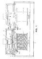
- Fig.l eine Vorderansicht der erfindungsgemäßen Aufwickelvorrichtung für drahtförmiges Gut,
- Fig.2 eine entsprechende Draufsicht.
- In dem veranschaulichten Doppelspuler befinden sich die beiden Spulen 1 und 2 in vertikaler Anordnung, wobei ihre Achsen in einem Maschinenrahmen 3 so gelagert sind, daß sie im Abstand zueinander parallel verlaufen. Der Antrieb der Spulen, und zwar in gleichsinniger Drehrichtung, erfolgt dabei von oben über eine einzige Antriebseinheit 4, die zwischen den beiden Spulen verfahrbar ist. Als Antriebsmittel kann beispielsweise ein an sich bekannter elektromotorischer Regelantrieb Verwendung finden, der auf einer Tragplatte 6 montiert ist, welche in einem Rahmen 5 über Führungsrollen 7 an ihren Ecken in der Höhe verfahren werden kann.
- Für den wechselseitigen Antrieb jeweils einer der beiden Spulen läßt sich der Rahmen 5 mit der Antriebseinheit 4 über Laufrollenpaare 8 auf Laufschienen am Maschinenrahmen 3 horizontal verfahren.
- Mit dem Spulenantrieb 4 drehfest verbunden ist ein Flansch 11, der über einen Mitnehmer lla durch Absenken der Tragplatte 6 in den oberen Flansch der zu bewickelnden Spule eingreift, während das Antriebswellenende 4a gleichzeitig als Gegenlager für die Spule dient.
- Erfindungsgemäß sind eine mit dem Spulenantrieb gekoppelte Einrichtung 13 zum Fangen und Klemmen des Wickelgutes sowie ferner eine Trenneinrichtung 14 vorgesehen, die eine Baueinheit bilden und auf dem Flansch 11 installiert sind sowie über Hydraulikzylinder 15 betätigt werden.
- Für das Querverfahren des Rahmens 5 mit der Antriebseinheit 4 einschließlich der Fang-, Klemm- und Trenneinrichtung sowie für das Höhenverfahren der Tragplatte 6 zum Zwecke des Umlegens des Wickelgutes von der vollen auf die leere Spule und des antriebsmäßigen Ein- und Auskuppelns mit den Spulen dienen an sich bekannte Mittel, auf die im einzelnen nicht näher eingegangen werden soll. Ihre Bewegungsabläufe erfolgen in zeitlicher Abstimmung mit dem Wickelvorgang sowie mit den Bewegungsabläufen für das Fangen, Klemmen und Trennen des Wickelgutes.
- Die Vorrichtung zum Aufwickeln eines drahtförmigen Gutes arbeitet folgendermaßen:
- In bekannter Weise wird das Wickelgut über eine Verlegeeinrichtung 16 der zu bewickelnden Spule 1 zugeführt und auf dieser lagenweise verlegt. Am Ende des Wickelvorgangs befindet sich das zulaufende
- Nach dem Fangen und Klemmen des Wickelgutes wird die bewickelte Spule 1 zum Stillstand abgebremst, alsdann erfolgt das Durchtrennen in der Trenneinrichtung 14, worauf eine pneumatisch betätigte Andrückvorrichtung 17 das spulenseitige Wickelgutende an der Spule hält.
- Mit dem geklemmt gehaltenen neuen Wickelgutanfang verfährt die Fang- und Klemmeinrichtung 13 gemeinsam mit der Trenneinrichtung 14 seitwärts über die bereitstehende leere Spule 2, nachdem zuvor die Kopplung der Antriebseinheit 4 mit der vollen Spule 1 durch Anheben der Tragplatte 6 sowie ein Zurückschwenken der Fang-, Klemm- und Trenneinrichtung in ihre Ausgangsposition erfolgte. Gleichzeitig mit dem Querverfahren vollzieht sich die Mitnahme der Verlegeeinrichtung 16. Die strichpunktierten Zeichnungen sollen die einzelnen Bewegungsphasen verdeutlichen.
- Die vollgewickelte Spule 1 kann nun in bekannter Weise abgebunden und sodann ungehindert aus ihrer Lagerung entfernt und durch eine leere Spule ersetzt werden.
- Durch Absenken der Tragplatte 6 wird nun die leere Spule 2 mit dem Mitnehmer lla des Antriebsflansches 11 gekoppelt und somit in Umlaufbewegung versetzt, während der Wickelgutanfang von der mit umlaufenden Fang- und Klemmeinrichtung oberhalb des Spulenflansches gehalten und somit das Wickelgut durch die Verlegeeinrichtung 16, die sich unterhalb des oberen Spulenflansches befindet, unmittelbar an den Kern der leeren Spule herangeführt und nach einigen Wickellagen von der Fang- und Klemmeinrichtung freigegeben wird.
- Am Ende des Wickelvorgangs führen die Fang-, Klemm- und Schneideinrichtung wieder eine Schwenkbewegung in den Verlegebereich aus zum Aufnehmen des Wickelgutendes in analoger Weise wie vorstehend beschrieben.
- Die Erfindung beschränkt sich nicht auf das dargestellte und beschriebene Ausführungsbeispiel, sie läßt vielmehr zahlreiche Abwandlungen im Rahmen der Erfindung zu. Anstelle der Doppelspulenanordnung läßt sich die Erfindung ebenso für eine Einfachspulenanordnung verwenden, wobei dann der Rahmen 5 in eine seitliche Warteposition und nach dem Wechsel der vollen Spule gegen eine leere wieder zurückverfahren wird. In einer weiteren abgewandelten Ausführung können die Spulen jeweils separate Antriebe aufweisen und die Fang-, Klemm- und Schneideinrichtung an einem al Gegenlager dienenden, auf der dem Antrieb gegenüberliegenden Seite angeordneten Flansch installiert sein, der mit dem oberen Flansch der zu bewickelnden Spule ein- und auskuppelbar ist bzw. über einen eigenen Antrieb verfügt. Des weiteren bleibt es der Ausführung überlassen, ob der Rahmen 5 zwischen den beiden Spulen linear verfahren oder verschwenkt wird.
- Um bei hohen Wickelgeschwindigkeiten die umlaufenden Massen sowie die Umwucht gering zu halten, können die Fang-, Klemm- und Trenneinrichtung an einem separaten Bauteil installiert sein und ausschließlich zu Beginn und zum Ende des Wickelvorgangs mit der Spule umlaufend angetrieben werden.
- Auch ist es nicht zwingend erforderlich die Trenneinrichtung am umlaufenden Flansch 11 zu installieren und folglich mit rotieren zu lassen. Letztlich wäre eine Ausführung denkbar, die vorsieht, die Einrichtungen zum Fangen, Klemmen und Schneiden des Wickelgutes oberhalb des Spulenflansches zu positionieren und die Verlegeeinrichtung derart zu steuern, daß sie über den Spulenflansch hinausfährt und dabei das Wickelgut in die Fang- und Klemmeinrichtung sowie gleichzeitig in die Trennvorrichtung leitet.
Claims (8)
Priority Applications (2)
| Application Number | Priority Date | Filing Date | Title |
|---|---|---|---|
| EP19840114099 EP0181960B1 (de) | 1984-11-22 | 1984-11-22 | Vorrichtung zum Aufwickeln eines drahtförmigen Gutes |
| DE8484114099T DE3469432D1 (en) | 1984-11-22 | 1984-11-22 | Apparatus for reeling a wire-like material |
Applications Claiming Priority (1)
| Application Number | Priority Date | Filing Date | Title |
|---|---|---|---|
| EP19840114099 EP0181960B1 (de) | 1984-11-22 | 1984-11-22 | Vorrichtung zum Aufwickeln eines drahtförmigen Gutes |
Publications (2)
| Publication Number | Publication Date |
|---|---|
| EP0181960A1 true EP0181960A1 (de) | 1986-05-28 |
| EP0181960B1 EP0181960B1 (de) | 1988-02-24 |
Family
ID=8192300
Family Applications (1)
| Application Number | Title | Priority Date | Filing Date |
|---|---|---|---|
| EP19840114099 Expired EP0181960B1 (de) | 1984-11-22 | 1984-11-22 | Vorrichtung zum Aufwickeln eines drahtförmigen Gutes |
Country Status (2)
| Country | Link |
|---|---|
| EP (1) | EP0181960B1 (de) |
| DE (1) | DE3469432D1 (de) |
Cited By (5)
| Publication number | Priority date | Publication date | Assignee | Title |
|---|---|---|---|---|
| EP0304606A3 (de) * | 1987-08-26 | 1989-06-28 | kabelmetal electro GmbH | Anlage zum Ablängen, Wickeln und Abbinden von Wickelgut |
| EP0578395A1 (de) * | 1992-07-10 | 1994-01-12 | Mackie International Limited | Garnübertragungseinrichtung |
| WO2014005734A1 (en) * | 2012-07-04 | 2014-01-09 | Nv Bekaert Sa | Transfer of an elongated element from one spool to another spool |
| CN104803233A (zh) * | 2015-04-24 | 2015-07-29 | 广东精迅里亚特种线材有限公司 | 低速绕线机组单人换盘系统及其方法 |
| CN107487661A (zh) * | 2017-07-20 | 2017-12-19 | 朱新超 | 一种纺织绕线器 |
Citations (5)
| Publication number | Priority date | Publication date | Assignee | Title |
|---|---|---|---|---|
| US3347477A (en) * | 1965-06-29 | 1967-10-17 | Thomson Houston Comp Francaise | Continuous wire winding device |
| DE2049615A1 (en) * | 1969-10-20 | 1971-05-13 | Mag Masch App | Wire winding machine spool changing |
| DE2610393B1 (de) * | 1976-03-12 | 1977-09-15 | Niehoff Kg Maschf | Vorrichtung zum kontinuierlichen aufwickeln von stranggut, insbesondere von draht |
| DE3215573A1 (de) * | 1982-04-27 | 1983-11-03 | Maschinenfabrik Niehoff Kg, 8540 Schwabach | Einzelspuler mit automatischem spulenwechsel zum aufwickeln von stranggut, insbesondere von draht |
| DE3325101A1 (de) * | 1983-07-12 | 1985-01-24 | Reinking Maschinenbau GmbH, 4993 Rahden | Vorrichtung zum aufwickeln eines drahtfoermigen gutes |
-
1984
- 1984-11-22 EP EP19840114099 patent/EP0181960B1/de not_active Expired
- 1984-11-22 DE DE8484114099T patent/DE3469432D1/de not_active Expired
Patent Citations (5)
| Publication number | Priority date | Publication date | Assignee | Title |
|---|---|---|---|---|
| US3347477A (en) * | 1965-06-29 | 1967-10-17 | Thomson Houston Comp Francaise | Continuous wire winding device |
| DE2049615A1 (en) * | 1969-10-20 | 1971-05-13 | Mag Masch App | Wire winding machine spool changing |
| DE2610393B1 (de) * | 1976-03-12 | 1977-09-15 | Niehoff Kg Maschf | Vorrichtung zum kontinuierlichen aufwickeln von stranggut, insbesondere von draht |
| DE3215573A1 (de) * | 1982-04-27 | 1983-11-03 | Maschinenfabrik Niehoff Kg, 8540 Schwabach | Einzelspuler mit automatischem spulenwechsel zum aufwickeln von stranggut, insbesondere von draht |
| DE3325101A1 (de) * | 1983-07-12 | 1985-01-24 | Reinking Maschinenbau GmbH, 4993 Rahden | Vorrichtung zum aufwickeln eines drahtfoermigen gutes |
Cited By (9)
| Publication number | Priority date | Publication date | Assignee | Title |
|---|---|---|---|---|
| EP0304606A3 (de) * | 1987-08-26 | 1989-06-28 | kabelmetal electro GmbH | Anlage zum Ablängen, Wickeln und Abbinden von Wickelgut |
| EP0578395A1 (de) * | 1992-07-10 | 1994-01-12 | Mackie International Limited | Garnübertragungseinrichtung |
| WO2014005734A1 (en) * | 2012-07-04 | 2014-01-09 | Nv Bekaert Sa | Transfer of an elongated element from one spool to another spool |
| CN104428229A (zh) * | 2012-07-04 | 2015-03-18 | 贝卡尔特公司 | 细长元件从一个卷轴向另一卷轴的传递 |
| CN104428229B (zh) * | 2012-07-04 | 2017-04-26 | 贝卡尔特公司 | 细长元件从一个卷轴向另一卷轴的传递 |
| US9708152B2 (en) | 2012-07-04 | 2017-07-18 | Nv Bekaert Sa | Transfer of an elongated element from one spool to another spool |
| CN104803233A (zh) * | 2015-04-24 | 2015-07-29 | 广东精迅里亚特种线材有限公司 | 低速绕线机组单人换盘系统及其方法 |
| CN104803233B (zh) * | 2015-04-24 | 2018-05-18 | 广东精迅里亚特种线材有限公司 | 低速绕线机组单人换盘系统及其方法 |
| CN107487661A (zh) * | 2017-07-20 | 2017-12-19 | 朱新超 | 一种纺织绕线器 |
Also Published As
| Publication number | Publication date |
|---|---|
| DE3469432D1 (en) | 1988-03-31 |
| EP0181960B1 (de) | 1988-02-24 |
Similar Documents
| Publication | Publication Date | Title |
|---|---|---|
| DE3348034C2 (de) | ||
| DE3312116C2 (de) | ||
| EP1283288A2 (de) | Anspinnvorrichung in einer Offenend-Rotorspinnmaschine | |
| CH691486A5 (de) | Transportsystem an einer Topfspinnmaschine. | |
| DE3339670A1 (de) | Verfahren und vorrichtung zum steuern und wiederaufnehmen des abgeschnittenen fadens beim austausch von vollen spulen | |
| DE3137990C2 (de) | Verfahren und Vorrichtung zum kontinuierlichen Spulenwechsel an ein- oder mehrgängigen, kontinuierlich arbeitenden, ortsfesten Wickelstationen für strangförmiges Gut | |
| DE4108929A1 (de) | Topfspinnvorrichtung | |
| DE68925017T2 (de) | Automatisches Ansetzen eines Faserbandes in einer Textilmaschine. | |
| DE19523938B4 (de) | Topfspinnmaschine | |
| DE69822592T2 (de) | Aufwickelvorrichtung insbesondere für Garn | |
| EP0181960A1 (de) | Vorrichtung zum Aufwickeln eines drahtförmigen Gutes | |
| DE3325101A1 (de) | Vorrichtung zum aufwickeln eines drahtfoermigen gutes | |
| EP0301330A1 (de) | Verfahren und Vorrichtung zum Wechseln von Spinnkannen bei einer Spinnereivorbereitungsmaschine | |
| EP1127831B1 (de) | Vorrichtung zur Inbetriebnahme einer Arbeitsstelle einer Kreuzspule herstellenden Textilmaschine | |
| EP0410021A1 (de) | Betriebsverfahren und Vorrichtung zum automatisierten Auswechseln von mit leeren Hülsen bestückten Spulenadaptern gegen mit vollen Vorlagespulen bestückte Spulenadapter im Bereich einer Fadenbearbeitungsstelle einer Textilmaschine | |
| DE3344993C2 (de) | Mehrstellige Textilmaschine | |
| CH663200A5 (de) | Verfahren zum erzeugen oder bearbeiten und aufwickeln von faeden. | |
| EP0295394A1 (de) | Verfahren und Vorrichtung zum Herstellen einer Fadenreserve | |
| DE3872220T2 (de) | Verfahren und vorrichtung zum auffinden eines endes eines textilfaserbandes und zum fuehren dieses endes in eine zufuehreinrichtung einer textilmaschine. | |
| CH637170A5 (de) | Verfahren und vorrichtung zum warten einer vielzahl nebeneinander angeordneter spinnstellen einer offenend-spinnmaschine. | |
| DE69112539T2 (de) | Vorrichtung zum automatischen Abnehmen von Spulen auf einer Vorspinnmaschine für Fasern und Kurzfasern und Verfahren zum Einsatz dieser Vorrichtung. | |
| DE4017303A1 (de) | Verfahren zur herstellung von kreuzspulen mit unterschiedlicher garnlaenge | |
| DE3643772C3 (de) | Textilmaschine | |
| DE2455913A1 (de) | Spinnmaschine und verfahren zum spulenwechseln | |
| DE2017652B2 (de) | Traversiervorrichtung in einer wickelbildungsvorrichtung |
Legal Events
| Date | Code | Title | Description |
|---|---|---|---|
| PUAI | Public reference made under article 153(3) epc to a published international application that has entered the european phase |
Free format text: ORIGINAL CODE: 0009012 |
|
| AK | Designated contracting states |
Kind code of ref document: A1 Designated state(s): DE FR GB IT SE |
|
| 17P | Request for examination filed |
Effective date: 19860605 |
|
| 17Q | First examination report despatched |
Effective date: 19861210 |
|
| D17Q | First examination report despatched (deleted) | ||
| GRAA | (expected) grant |
Free format text: ORIGINAL CODE: 0009210 |
|
| AK | Designated contracting states |
Kind code of ref document: B1 Designated state(s): DE FR GB IT SE |
|
| GBT | Gb: translation of ep patent filed (gb section 77(6)(a)/1977) | ||
| REF | Corresponds to: |
Ref document number: 3469432 Country of ref document: DE Date of ref document: 19880331 |
|
| ET | Fr: translation filed | ||
| ITF | It: translation for a ep patent filed | ||
| PLBE | No opposition filed within time limit |
Free format text: ORIGINAL CODE: 0009261 |
|
| STAA | Information on the status of an ep patent application or granted ep patent |
Free format text: STATUS: NO OPPOSITION FILED WITHIN TIME LIMIT |
|
| 26N | No opposition filed | ||
| ITTA | It: last paid annual fee | ||
| PGFP | Annual fee paid to national office [announced via postgrant information from national office to epo] |
Ref country code: FR Payment date: 19920921 Year of fee payment: 9 |
|
| PGFP | Annual fee paid to national office [announced via postgrant information from national office to epo] |
Ref country code: SE Payment date: 19921016 Year of fee payment: 9 |
|
| PGFP | Annual fee paid to national office [announced via postgrant information from national office to epo] |
Ref country code: GB Payment date: 19921110 Year of fee payment: 9 |
|
| PG25 | Lapsed in a contracting state [announced via postgrant information from national office to epo] |
Ref country code: GB Effective date: 19931122 |
|
| PG25 | Lapsed in a contracting state [announced via postgrant information from national office to epo] |
Ref country code: SE Effective date: 19931123 |
|
| GBPC | Gb: european patent ceased through non-payment of renewal fee |
Effective date: 19931122 |
|
| PG25 | Lapsed in a contracting state [announced via postgrant information from national office to epo] |
Ref country code: FR Effective date: 19940729 |
|
| REG | Reference to a national code |
Ref country code: FR Ref legal event code: ST |
|
| PGFP | Annual fee paid to national office [announced via postgrant information from national office to epo] |
Ref country code: DE Payment date: 19941121 Year of fee payment: 11 |
|
| EUG | Se: european patent has lapsed |
Ref document number: 84114099.9 Effective date: 19940610 |
|
| PG25 | Lapsed in a contracting state [announced via postgrant information from national office to epo] |
Ref country code: DE Effective date: 19960801 |