EP0183273A2 - Flexibel anwendbares serielles Interface-System für eine Verbindung zwischen einer und mehreren Einheiten - Google Patents
Flexibel anwendbares serielles Interface-System für eine Verbindung zwischen einer und mehreren Einheiten Download PDFInfo
- Publication number
- EP0183273A2 EP0183273A2 EP85115176A EP85115176A EP0183273A2 EP 0183273 A2 EP0183273 A2 EP 0183273A2 EP 85115176 A EP85115176 A EP 85115176A EP 85115176 A EP85115176 A EP 85115176A EP 0183273 A2 EP0183273 A2 EP 0183273A2
- Authority
- EP
- European Patent Office
- Prior art keywords
- slave
- signal
- master unit
- interface
- slave units
- Prior art date
- Legal status (The legal status is an assumption and is not a legal conclusion. Google has not performed a legal analysis and makes no representation as to the accuracy of the status listed.)
- Granted
Links
Images




Classifications
-
- G—PHYSICS
- G06—COMPUTING OR CALCULATING; COUNTING
- G06F—ELECTRIC DIGITAL DATA PROCESSING
- G06F13/00—Interconnection of, or transfer of information or other signals between, memories, input/output devices or central processing units
- G06F13/38—Information transfer, e.g. on bus
- G06F13/42—Bus transfer protocol, e.g. handshake; Synchronisation
- G06F13/4282—Bus transfer protocol, e.g. handshake; Synchronisation on a serial bus, e.g. I2C bus, SPI bus
- G06F13/4291—Bus transfer protocol, e.g. handshake; Synchronisation on a serial bus, e.g. I2C bus, SPI bus using a clocked protocol
Definitions
- This invention relates to a serial interface system which comprises a master unit, a plurality of slave units, and a serial interface shared by the master and the slave units.
- a serial interface system is described in United States Patent No. 4,348,722 issued to Thomas G. Gunter et al and assigned to Motorola, Inc. Such a serial interface system is used, above all, in a portable terminal equipment which may be a terminal equipment on board a mobile in a mobile communication network.
- a conventional serial interface system may comprise a standard interface, such as the RC-232C.
- the RC-232C is an asynchronous interface.
- Another conventional interface system comprises a synchronous serial interface, such as used in a 72-chip central processing unit.
- the latter interface is operable at a high speed and has merits in hardware as well as in software when used in a one-to-one connection.
- the conventional serial interface must, however, comprise a chip select (CS) line for each unit when applied to a one-to-multiplicity connection. This makes it hardly possible to apply the serial interface system to a connection for a master unit and five or more slave units.
- the serial interface system is not flexible for a change in the connection or an increase in the number of slave units.
- a serial interface system as comprising a master unit, a plurality of slave units, and a serial interface for communication between at least two of the master and the slave units.
- the master unit comprises energizing means connected to the interface for energizing the interface when the energizing means is activated.
- the above-defined system further comprises activating means for controllably activating the energizing means when one of the master and the slave units begins the communication.
- the activating means comprises a control path which is shared by the master and the slave units and is always and selectively activated when the master and one of the slave units begin the communication, respectively.
- the control path activates, in turn, the energizing means when activated.
- the master unit further comprises first means for making the energizing means energize the interface with a first signal.
- the afore-defined system further comprises second means coupled to each slave unit for supplying the interface with a second signal. Either of the first and the second signals is for activating the energizing means. The first and the second means thereby collectively serve as the activating means.
- the system comprises a master unit 21, first and second slave units 26 and 27, and other slave units (not shown).
- Each of the master and the slave units may be a microprocessor.
- Each slave unit may be one of devices of various types, such.as a telephone handset, a facsimile device, a computer, a radio transmitter/receiver or modem, a test equipment, and an adapter for such devices. It should be noted that each of such devices should comprise a processor.
- the first, the second, and the other slave units 26, 27, and so forth are preliminarily assigned with identification numbers, respectively, in a predetermined order which may be an ascending order.
- the serial interface system comprises a serial interface consisting of first and second paths or routes 31 and 32, a clock path 33, and a control path 34.
- Each path may be a wiring or a radio channel.
- the first and the second paths 31 and 32 are for primarily transmitting data signals between the master unit 21 and one or more slave units.
- the clock path 33 is for transmitting a clock signal from the master unit 21 to each slave unit for the data signals transmitted through the first and the second paths 31 and 32. Only the first, the second, and the clock paths 31 through 33 are referred to collectively as a serial interface or I/O path depending on the circumstances.
- the control path 34 will later become clear.
- the master unit 21 comprises a central processor 35.
- master receiver and transmitter 36 and 37 are coupled to the central prccessor 35 in the manner which will become clear as the description proceeds.
- a clock generator 38 is controlled by the central processor 35 .
- the master receiver and transmitter 36 and 37 and the clock generator 38 are connected to the first, the second, and the clock paths 31 through 33, respectively.
- each slave unit comprises a slave processor 39 and slave transmitter and receiver 41 and 42 coupled to the slave processor 39.
- the slave transmitter 41 is connected to the first path 31.
- the slave receiver 42 is connected to the second and the clock paths 32 and 33,
- the first path 31 therefore primarily serves as an input data path for the master unit 21 and as an output data path for each slave unit.
- the second path 32 primarily serves as an output data path for the master unit 21 and as an input data path for each slave unit.
- Figs. 2 through 4 operation of the serial interface system will be described with assumptions such that sixteen or less slave units 26, 27, and so on are connected to the serial interface and that sixteen or less bytes are transmitted as the data signal between a pair of units of the master and the slave units 21, 26, 27, and others.
- Each frame of the data signal consists of eight bits.
- Fig. 2 shows only two frames.
- the clock generator 38 (Fig. 1) generates eight clock pulses of the clock signal in each frame in the manner indicated at SCK (synchronization clocks) in detail as regards a first frame depicted at a lefthand end in Fig. 2.
- the communication through the serial interface 31-33 is transmission of a data signal of a certain duration from the master unit 21 to either the first slave unit 26 or the second slave unit 27.
- the clock generator 35 Controlled by the central processor 35, the clock generator 35 sends the clock signal SCK to the clock path 33 at first during the first frame.
- the master transmitter 37 samples information as information samples whenever the clock signal SCK builds down. The master transmitter 37 thereby sends eight information samples to the slave units 26, 27, and others in each frame through the second path 32 as a serial data output SO of the data signal.
- the clock generator 38 In the first frame, four preceding bits 43 of the information samples are used as an identification code representative of the identification number of the slave unit of a destination to which the data signal should be transmitted.
- Four succeeding bits 44 are used to indicate the number of bytes, or a byte number, representative of the duration of the data signal.
- the clock generator 38 Like in the first frame, the clock generator 38 generates the clock pulses during following frames of a number which is indicated by the four succeeding bits 44. Alternatively, the clock generator 38 is controlled by the central processor 35 so as to generate the clock pulses for each of such following frames until the number of the following frames reaches the number indicated.
- eight bits 45 of the information samples are representative of the data signal transmitted to the destination.
- the four preceding bits 43 should be given a specific code. In this event, the number of slave units should be fifteen or less.
- the slave units 26, 27, and so forth are capable of receiving signals from the serial interface 31-33. More specifically, the slave receiver 41 receives the clock signal SCK in each slave unit during the first frame. Responsive to the four preceding bits 41, the slave processor 39 decides whether or net the slave unit is the destination. Only the slave receiver 42 of the destination thereafter receives the data signal, such as 45, whenever the clock signal SCK builds up.
- the communication is transmission of a data signal from the second slave unit 27 to the master unit 21.
- a slave unit which begins the communication as a source or origin, may be called a particular slave unit.
- the slave transmitter 41 activates the control path 34 under the control of the slave processor 39.
- the activation is herein called a transmission request REQ and is indicated by a transition from a high level to a low level.
- the master receiver 36 receives the transmission request REQ through the control path 34.
- the central processor 35 carries out polling successively to the slave units 26, 27, and so on in a predetermined order, such as in the ascending order, until the source is located.
- the master transmitter 37 With the clock signal SCK sent to the clock path 33, the master transmitter 37 is made to carry out the polling in a polling cycle consisting of first and second frames. It is possible to make the central processor 35 carry out the polling with other operations interrupted.
- the master transmitter 37 sends a polling signal 461 to the second path 32 as the serial data output SO during the first frame of a first polling cycle
- the polling signal 461 comprises an identification code indicative of the identification number which stands foremost in the ascending order for the first slave unit 26.
- the master receiver 36 receives no answer from any one of the slave units 26, 27, and others in the manner depicted along a line representative of a serial data input SI to the master unit 21.
- the master transmitter 37 sends another polling signal 462 to the second path 32.
- the polling signal 462 indicates the identification number of the second slave unit 27.
- the slave receiver 42 receives the serial data output SO. Responsive to the identification number indicated by the serial data output SO, the slave processor 39 knows that the second slave unit 27 is polled.
- the slave processor 39 of the second slave unit 27 makes the slave transmitter 41 send a transmission request signal 47 as an answer signal to the first path 31.
- the transmission request signal 47 represents the identification number of the second slave unit 27 and the number of bytes of the data signal which should be transmitted to the master unit 21.
- the central processor 35 makes the clock generator 38 generate the clock pulses of a number which corresponds to the number of bytes in the manner depicted along a line labelled SCK.
- the slave transmitter 41 sends the data signal to the master unit 21.
- the slave processor 39 makes the slave transmitter 41 render the control pith 34 inactive to inform the master unit 21 of the completion.
- the communication is transfer of a data signal from the first slave unit 26 to the second slave unit 27.
- the first and the second slave units 26 and 27 are a source or origin and a destination of the data signal to be transferred.
- the first slave unit 26 activates the control path 34.
- the master unit 21 sends the polling signal 461 as the serial data output SO (Fig. 4).
- the first slave unit 26 sends a transfer request signal 48 in the second frame of the first polling cycle as the serial data input SI for the master unit 21.
- the transfer request signal 48 may again represent the identification number of the source 26 and represents the identification number of the destination 27. In the manner which will shortly become clear, the transfer request signal 48 is a part of an answer signal.
- the master unit 21 sends the clock signal SCK to the slave units 26, 27, and others in a first frame which next follows the polling cycle.
- the serial interface 31-33 comprises a switch 481 adjacent to each of the master and the slave units 21, 26, 27, and so on.
- the switch 481 is controlled by a pertinent one of the central processor 35 and the slave processors, such as 39.
- a three-state buffer 482 is used in the second path 32 between the switch 481 and the master unit 21 and in the first path 31 between the switch 481 and each slave unit.
- the buffer 482 is for avoiding collision of signals in the known manner.
- the buffer 482 is controlled by a relevant one of the central processor 35 and the slave processors.
- the central processor 35 responds to the transfer request signal 48 to switch the first and the second paths 31 and 32 from a usual state to a temporary state by activating the switches 481 in cooperation with the source 26.
- the first path 31 is connected in the temporary state to the master transmitter 37 and to the slave receiver of the source 26.
- the first path 31 is connected to the slave transmitters, such as 41, of other slave units 27 and so forth as in the usual state.
- the second path 32 is connected to the master receiver 36 and to the slave transmitter 42 of the source 26. Like in the usual state, the second path 32 is connected to the slave receivers, such as 42, of the other slave units.
- the master unit 21 sends the clock signal SCK to the clock path 33.
- the source 26 sends a transfer request signal 49 to the second path 32 as a remaining part of the answer signal. Except for transmission through the second path 32, the transfer request signal 49 is similar to the transmission request signal 47 of Fig. 3 and indicates the identification number of the destination 27 and the number of bytes of the data signal to be transferred from the source 26 to the destination 27.
- the data signal is transferred from the source 26 to the destination 27 in the manner described above with reference to Fig. 3 .
- the control path 34 is rendered inactive upon completion of the transfer, the master unit 21 switches the first and the second paths 31 and 32 from the temporary state back to the usual state. The transfer comes to an end.
- the control path 34 serves as an activating arrangement for controllably activating the energizing arrangement when one of the master unit 21 and the slave units 26, 27, and others begins communication through the interface 31-33. It is possible to understand that the activating arrangement 34 is always activated when the master unit 21 begins the communication. The activating arrangement 34 is selectively activated when one of the slave units 26, 27, and so forth begins the communication. Activated in this manner, the activating arrangement 34 activates, in turn, the energizing arrangement 35-37.
- the master unit 21 is connected to a plurality of slave units, such as 26 and 27, through the serial interface 31-33. Transmission of a data signal is possible from the master unit 21 to one or more of the slave units.
- the serial interface system is therefore applicable to a one-to-plurality or one-to-multiplicity connection. Together with the master unit 21, a plurality of slave units are connected together through the interface 31-33. Transfer of a data signal is possible from any one of the slave units to one or more of other slave units.
- the serial interface system is therefore applicable also to a plurality-to-plurality connection.
- the serial interface system is flexible. More particularly, a change is possible in the system by only adapting the central processor 35 to the change even in the severest case.
- the slave units can be increased or descreased in number provided that the afore-mentioned identification code is capable of differentiating the slave units when the slave units are increased.
- the serial interface system is operable at a high speed as described heretobefore. It may be mentioned here that the activating arrangement 34 makes it possible to use the serial interface 31-33 as a bus..
- the serial interface system comprises a master unit, eight or less slave units, and a serial interface.
- the master unit is equivalent to that described in conjunction with Fig. 1 and will therefore be designated by the reference numeral 21.
- the slave units are zeroth through seventh slave units 50, 51, 52, 53, 54, 55, 56, and 57.
- the serial interface, depicted at 59, need not include the control path 34 (Fig. 1).
- serial data output and input SO and SI and a clock signal SCK are transmitted through the serial interface 59 in the manner which is described above and will again be described hereunder. It will be assumed that each frame ccnsists of eight bits.
- the serial data output SO is sent either from the master unit 21 or from one of the slave units 50 through 57 when the clock signal SCK builds down.
- the serial data input SI is received either at the master unit 21 or at one or more of the slave units 50 to 57 when the clock signal SCK builds up.
- each frame of the serial data output SO is a succession of a C/D bit, three identification bits ID2, ID1, and IDO, and four information bits I3, 12, I1, and I0.
- the serial data input SI has a format which is not different from that of the serial data output SO because the serial data output SO is received as the serial data input SI through the interface 59.
- the C/D bit is used in indicating whether the frame is used as a command signal or a frame of a data signal. namely, whether the information bits I (affixes omitted) represent a command or a datum.
- the identification bits ID (affixes omitted) give an identification code representative of an identification number assigned to each slave unit in the manner already described.
- the information bits I are capable of representing up to sixteen commands when the C/D bit indicates a command signal.
- the information bits I can be used as one of up to sixteen command codes.
- Each command code is used generally both in the master unit 21 (Fig. 6) and in each slave unit.
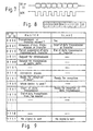
- command codes are used in the manner which is briefly shown in Fig. 9 and will be described in the following.
- the command codes will be called by names used hereunder.
- Transmission from the master unit indicates an interrogation to the slave units as regards presence and absence of a transmission or transfer request in one of the slave units.
- the master unit can send the zeroth command code in a frame with the zeroth command code preceded in the frame by an identification code for a selected one of the slave units.
- the selected one of the slave units sends the zeroth command cede as a reply to the zeroth command code directed thereto from the master unit. This informs the master unit of the fact that the selected one of the slave units has a data signal which should be either transmitted to the master unit or transferred to one or more of other slave units.
- the selected one of the slave units may send the zeroth command code with the identification code representative of the identification number assigned thereto. This enables the master unit confirm the reply.
- the slave units have neither a transmission request nor a transfer request, the slave units are quiescent and send nothing to the interface in response to the interrogation.
- Transmission from the master unit indicates allowance for the data transmission or trasfer.
- the selected one of the slave units sends the first command code in reply in order to indicate start of the data transmission or transfer.
- Transmission from the master unit indicates forced suspension of the data transmission and transfer during reception of the data signal and during the data transfer.
- Transmission from a slave unit indicates an end of the data transmissior or transfer. The selected one of the slave units sends the first command code also in response to the forced suspension.
- Transmission from the master unit indicates a request for retransmission of the data signal during reception of the data signal from the selected one of the slave units.
- Transmission from the master unit indicates a request to the selected one of the slave units for transmission of parity data which may be calculated in the slave unit having received the request in accordance with the data signal which are already received by the selected one of the slave units before reception of the request.
- This command code is used by the master unit during a series of initializing processes, such as switch on of a power source (not shown).
- the slave units are initialialized. For example, flags are initialized which should be produced by the slave processors, such as 39 (Fig. 1).
- the master unit On transmitting a data signal either to a selected one or to all of the slave units, the master unit sends the seventh command code to the serial interface in order to interrogate whether the slave unit or units are busy or ready for reception of the data signal. Interrogated by an accompanying identification code, the slave unit sends the seventh command code to the serial interface when it is ready for the reception. The slave unit is quiescent when it is busy.
- the master unit may send the eighth command code to one of the slave units that is selected as a questioned slave unit. This is to interrogate which of a plurality of devices, such as a telephone handset exemplified heretobefore, is for use in the questioned slave unit.
- the questioned slave unit may send a data code given by the four information bits I. In this event, the data code can represent one of sixteen or less types of the device.
- Transmission from the master unit indicates start of data transmission either to a selected one or to all of the slave units.
- the slave unit sends the ninth command code to the serial interface.
- the slave unit is quiescent. The reception is impossible when the slave unit in question is busy.
- Transmission from the master unit indicates an end of the data transmission to the selected one or to all of the slave units.
- the fifteenth command code 1111 is used in indicating that no signal is sent to the serial interface either from the master unit or from any one of the slave units.
- the master unit 21 sends the ninth command code to the serial interface 59 at a step 61. It will be surmised merely for simplicity of description that all slave units 50 to 57 are capable of receiving the ninth command code. Having received the ninth command code through the serial interface 59, all slave units send the ninth command code to the serial interface 59 at a step 62 which next follows the step 61. The master unit 21 thereby knows that all slave units are ready for reception.
- the master unit 21 sends an addressing signal to the serial interface 59 at another step 61. In the addressing signal, the identification code represents an identification number of the destination.
- the master unit 21 sends eight clock pulses of the clock signal SCK to the serial interface 59. Responsive to the clock pulses, the destination sends the seventh command code to the serial interface 59 as an acknowledge signal in which the identification code represents the identification number of the destination.
- the master unit 21 checks the acknowledge signal at 65. When the acknowledge signal is not correctly received, the master unit 21 carries out error processing at 66 in the known manner.
- the master unit 21 When the acknowledge signal is correctly received at 65. the master unit 21 sends the clock signal SCK to the serial interface 59 and a byte of the data signal as the serial data output SO at 67. The data byte is received by the destination in synchronism with the cleck signal SCK. The master unit 21 checks at 6E whether or not all bytes of the data signal are already sent up to the number of bytes indicated by the addressing signal at 63. Until transmission of all bytes, steps 67 and 68 are repeated. When all bytes are already transmitted, operation of the master unit 21 proceeds to transmission termination processing at 69. In this manner, the data signal is received by the destination as received data.
- the master unit 21 sends the fourth command code to the destination at 71 together with the identification code of the destination.
- the destination transmits parity data for the received data back to the master unit 21 at 72.
- the master unit 21 checks the parity data. If the check indicates that the received data are incorrect, the master unit 21 carries out error processing as at 66. When the check shows correct reception, the master unit 21 sends the tenth command code to the destination at 73. The data transmission comes to an end.
- a data signal transmission of a data signal will be described for a case where one of the slave units 50 to 57 acts as a source or origin and transmits the data signal to the master unit 21.
- the identification number assigned to the source will be called a particular identification number for convenience of description.
- the source is given data which should be transmitted as the data signal. The source is aware of the number of bytes of the data and keeps the number. It will again be presumed that the data signal is transmitted by the use of various command codes defined before.
- the master unit 21 (Fig. 6) transmits at 76 a polling signal to all slave units.
- the polling signal comprises the zeroth command code and an identification code for one of the slave units 50 to 57.
- the master unit 21 sends eight clock pulses of the clock signal SCK to the serial interface 59. Being identified by the identification code, one of the slave units 50 to 57 receives the zeroth command code.
- the slave unit checks whether or not data are given thereto for transmission to the master unit 21. If the identification code represents the particular identification number, the slave unit is the source and sends the zeroth command code back to the master unit 21. When a plurality of slave units are simultaneously given data for transmission to the master unit 21, one thereof responds to the polling signal that is first identified by the identification code.
- the-master unit 21 checks whether or not the zeroth command code is received as a transmission request signal together with the number of bytes from a slave unit in response to the polling signal..When no zeroth command code is received, the master unit 21 checks at 79 whether or not all identification codes are already used. If not, the master unit 21 selects another identification code at 80 to repeat steps 76 through 79. If all identification codes are already used, operation of the master unit 21 proceeds to error processing at 81. In the absence of errors, the master unit 21 is ready for other communication operations.
- the master unit 21 When the master unit 21 detects at 78 reception of the transmission request signal from the source, the master unit 21 keeps the particular identification number and the number of bytes at 82. At 83, the master unit 21 sends eight clock pulses of the clock signal SCK to the serial interface 59 to make the source send one byte of the data and receives the one byte. The master unit 21 checks at 85 whether or not all bytes of the data are already received. If not, steps 83 and 84 are repeatedly carried out. Upon completion of reception of all. bytes, the master unit 21 carries out reception termination operation at 85. The reception termination operation 86 is similar to the transmission termination processing 69 (Fig. 11) except that the source sends the second command code in response to the clock signal SCK sent from the master unit 21 and in compliance with the number of bytes kept in the source.
- description will proceed to transfer of a data signal from one of the slave units 50 to 57 used as a source to another thereof that is used as a destination.
- the source is assigned with a particular identification number as above.
- the identification number assigned to the destination will be called a specific identification number.
- the source is given data which should be transferred to the destination as the data signal. It is surmised that the command codes are used as before in transferring the data.
- the master unit 21 (Fig. 6) sends a polling signal at 86 and eight clock pulses of the clock signal SCK at 87 to the serial interface 59, receives the zeroth command code from the source as a transfer request signal, and checks the transfer request signal at 88. Steps 86 through 88 are similar to steps 76 through 75 described in connection with Fig. 12. The master unit 21 moreover checks use of all identification codes, changes the identification code, and may carry out error processing at 89, 90, and 91 like in steps 79 through 81.
- the master unit 21 When the master unit 21 receives the transfer request signal at 88, the master unit 21 receives the specific identification number at 92.
- the master unit 21 switches the first and the second paths 31 and 32 (Fig. 5) from the usual state to the temporary state at 93 for the source and then at 94 for the master unit 21.
- the master unit 21 sends eight clock pulses of the clock signal SCK to the serial interface 59 at 95 and checks at 96 whether or not the source has transferred all bytes of the data to the destination. After confirmation of transfer of all bytes, the master unit 21 switches the first and the second paths 31 and 32 back to the usual state at 97 for both the master unit 21 and the source in cooperation with the source. Transfer termination operation is carried out at 98 like the transmission termination processing or operation 69 and 85.
- the master unit 21 comprises a first arrangement which comprises as in Fig. 1 the central processor 35 and the master transmitter 36 and produces a command signal including either the ninth or the zercth command code.
- the command signal is used as a first signal in energizing the energising arrangement 35-37.
- each slave unit comprises a second arrangement which comprises the slave processor 39 and the slave transmitter 41 and produces the transmission or the transfer request signal as a second signal for use in energizing the energizing arrangement 35-37.
- the first and the second arrangements serve as the above-mentioned activating arrangement.
- the above-exemplified merits are achieved also by the serial interface system being illustrated.
- the transmission from the master unit and from one or more of the slave units and/or the transfer between two or more of the slave units is possible concurrently in a time division faschion.
- the concurrent transmission and/or transfer is facilitated particularly when the identification code is included in the command and the data signals for each of the slave units concerned.
- the serial interface system need not comprise the path switching arrangement described with reference to Fig. 5.
- the master unit 21 may comprise the master transmitter and receiver 37 and 36 and the clock generator 38 in a manner which is different from that illustrated with reference to Fig. 1.
Landscapes
- Engineering & Computer Science (AREA)
- Theoretical Computer Science (AREA)
- Physics & Mathematics (AREA)
- General Engineering & Computer Science (AREA)
- General Physics & Mathematics (AREA)
- Information Transfer Systems (AREA)
Applications Claiming Priority (4)
| Application Number | Priority Date | Filing Date | Title |
|---|---|---|---|
| JP251533/84 | 1984-11-30 | ||
| JP59251533A JPH0658655B2 (ja) | 1984-11-30 | 1984-11-30 | シリアルi/o方式 |
| JP59279194A JPS61157131A (ja) | 1984-12-28 | 1984-12-28 | 同期式シリアルインタフエ−ス |
| JP279194/84 | 1984-12-28 |
Publications (3)
| Publication Number | Publication Date |
|---|---|
| EP0183273A2 true EP0183273A2 (de) | 1986-06-04 |
| EP0183273A3 EP0183273A3 (en) | 1988-08-31 |
| EP0183273B1 EP0183273B1 (de) | 1992-09-23 |
Family
ID=26540235
Family Applications (1)
| Application Number | Title | Priority Date | Filing Date |
|---|---|---|---|
| EP85115176A Expired EP0183273B1 (de) | 1984-11-30 | 1985-11-29 | Flexibel anwendbares serielles Interface-System für eine Verbindung zwischen einer und mehreren Einheiten |
Country Status (6)
| Country | Link |
|---|---|
| US (1) | US4872003A (de) |
| EP (1) | EP0183273B1 (de) |
| AU (1) | AU578988B2 (de) |
| CA (1) | CA1242283A (de) |
| DE (1) | DE3586678T2 (de) |
| HK (1) | HK103293A (de) |
Cited By (4)
| Publication number | Priority date | Publication date | Assignee | Title |
|---|---|---|---|---|
| US4988989A (en) * | 1987-10-26 | 1991-01-29 | Sharp Kabushiki Kaisha | Master-slave communication system for stations having timer means |
| EP0419112A3 (en) * | 1989-09-19 | 1991-04-10 | Psion Plc | Serial data transmission |
| EP0660243A1 (de) * | 1993-12-17 | 1995-06-28 | International Business Machines Corporation | Erweitung des Adressenbereichs in einem modularen Rechner |
| WO1998035275A1 (de) * | 1997-02-10 | 1998-08-13 | Siemens Aktiengesellschaft | Höraktiver kommunikationsteilnehmer, kommunikationsverfahren und kommunikationssystem mit höraktiven kommunikationsteilnehmern |
Families Citing this family (26)
| Publication number | Priority date | Publication date | Assignee | Title |
|---|---|---|---|---|
| US5133054A (en) * | 1987-10-20 | 1992-07-21 | Sharp Kabushiki Kaisha | Data transmission apparatus for autonomously and selectively transmitting data to a plurality of transfer path |
| US5124980A (en) * | 1989-03-20 | 1992-06-23 | Maki Gerald G | Synchronous multiport digital 2-way communications network using T1 PCM on a CATV cable |
| US5249184A (en) * | 1990-01-30 | 1993-09-28 | Johnson Service Company | Network control system with improved reliability |
| US5224095A (en) * | 1990-01-30 | 1993-06-29 | Johnson Service Company | Network control system and method |
| US5182746A (en) * | 1991-03-28 | 1993-01-26 | Intel Corporation | Transceiver interface |
| JP2873515B2 (ja) * | 1991-03-29 | 1999-03-24 | マツダ株式会社 | 多重伝送方法 |
| US5323145A (en) * | 1992-03-02 | 1994-06-21 | Alcatel Network Systems, Inc. | Alarm collection architecture with redundant bus |
| JP2957354B2 (ja) * | 1992-05-13 | 1999-10-04 | 三菱電機株式会社 | 信号転送方法 |
| US5452330A (en) * | 1992-07-06 | 1995-09-19 | Digital Equipment Corporation | Bus-oriented switching system for asynchronous transfer mode |
| US5469434A (en) * | 1993-01-21 | 1995-11-21 | General Datacomm, Inc. | Distributed frame processing for time division multiplexing |
| US5553308A (en) * | 1993-03-05 | 1996-09-03 | Alcatel Network Systems, Inc. | Serial communication format and methodology |
| US5799018A (en) * | 1994-05-19 | 1998-08-25 | Nippon Telegraph And Telephone Corp. | Method and system for private communication with efficient use of bus type transmission path |
| US5805586A (en) * | 1995-05-02 | 1998-09-08 | Motorola Inc. | Method, device and data communication system for multilink polling |
| US5928345A (en) * | 1996-09-30 | 1999-07-27 | Rosemont Inc. | Field instrument with data bus communications protocol |
| KR100469749B1 (ko) * | 1997-12-26 | 2005-04-06 | 삼성전자주식회사 | 마스터의 이미지 버퍼를 통한 슬레이브 모듈의 제어회로 |
| JP2000293485A (ja) * | 1999-04-08 | 2000-10-20 | Matsushita Electric Ind Co Ltd | 通信インターフェース |
| DE19921589C2 (de) * | 1999-05-05 | 2002-10-24 | Siemens Ag | Verfahren zum Betrieb eines Datenübertragungssystems |
| US6275500B1 (en) * | 1999-08-09 | 2001-08-14 | Motorola, Inc. | Method and apparatus for dynamic control of talk groups in a wireless network |
| KR100631495B1 (ko) * | 1999-12-22 | 2006-10-09 | 엘지전자 주식회사 | 마이크로 프로세서 |
| TW561725B (en) * | 2001-02-14 | 2003-11-11 | Matsushita Electric Industrial Co Ltd | Communications setting method and communications setting system for power line communications system |
| JP2002351825A (ja) * | 2001-05-29 | 2002-12-06 | Rohm Co Ltd | 通信システム |
| DE10148878B4 (de) * | 2001-10-04 | 2006-03-02 | Siemens Ag | System und Verfahren zum Übertragen digitaler Daten |
| JP2004120030A (ja) * | 2002-09-24 | 2004-04-15 | Hitachi Ltd | 電子装置の同期制御方法 |
| US7765269B2 (en) * | 2003-11-05 | 2010-07-27 | Renesas Technology Corporation | Communications system, and information processing device and control device incorporating said communications system |
| TW201001289A (en) * | 2008-06-27 | 2010-01-01 | Silicon Motion Inc | Embedded system and hardware setting method |
| DE102013010277A1 (de) * | 2013-06-19 | 2014-12-24 | Giesecke & Devrient Gmbh | Verfahren zum Initiieren einer Datenübertragung |
Family Cites Families (16)
| Publication number | Priority date | Publication date | Assignee | Title |
|---|---|---|---|---|
| GB1221964A (en) * | 1967-04-18 | 1971-02-10 | Ibm | Data transmission system |
| US3633169A (en) * | 1970-05-28 | 1972-01-04 | Raytheon Co | Demand access digital-communications system |
| GB1365838A (en) * | 1972-04-21 | 1974-09-04 | Ibm | Data handling system |
| IT1047329B (it) * | 1975-09-30 | 1980-09-10 | C Olivetto E C S P A Ing | Dispositivo di teleaccensione e di inizzializzazione di un terminale |
| CA1086397A (en) * | 1976-09-14 | 1980-09-23 | Charles G. Diefenderfer | Polling an data communication system having a pulse position to binary address conversion circuit |
| US4156866A (en) * | 1976-10-07 | 1979-05-29 | Systems Technology Corporation | Multiple remote terminal digital control system |
| US4225918A (en) * | 1977-03-09 | 1980-09-30 | Giddings & Lewis, Inc. | System for entering information into and taking it from a computer from a remote location |
| US4173754A (en) * | 1977-03-17 | 1979-11-06 | General Electric Company | Distributed control system |
| FR2406916A1 (fr) * | 1977-10-18 | 1979-05-18 | Ibm France | Systeme de transmission de donnees decentralise |
| US4271505A (en) * | 1979-07-02 | 1981-06-02 | The Foxboro Company | Process communication link |
| NL189062C (nl) * | 1980-02-15 | 1992-12-16 | Philips Nv | Werkwijze en stelsel voor overdracht van datapakketten. |
| US4348722A (en) * | 1980-04-03 | 1982-09-07 | Motorola, Inc. | Bus error recognition for microprogrammed data processor |
| US4410985A (en) * | 1981-03-25 | 1983-10-18 | Hitachi, Ltd. | Data transmission system and method |
| US4518960A (en) * | 1982-11-23 | 1985-05-21 | Burroughs Corporation | Speed independent selector switch employing M-out-of-N codes |
| US4595921A (en) * | 1983-08-11 | 1986-06-17 | Wang Laboratories, Inc. | Method of polling to ascertain service needs |
| US4683531A (en) * | 1984-07-02 | 1987-07-28 | Ncr Corporation | Polling method for data processing system |
-
1985
- 1985-11-29 EP EP85115176A patent/EP0183273B1/de not_active Expired
- 1985-11-29 DE DE8585115176T patent/DE3586678T2/de not_active Expired - Fee Related
- 1985-11-29 CA CA000496510A patent/CA1242283A/en not_active Expired
- 1985-12-02 AU AU50551/85A patent/AU578988B2/en not_active Ceased
-
1988
- 1988-06-01 US US07/204,945 patent/US4872003A/en not_active Expired - Lifetime
-
1993
- 1993-09-30 HK HK1032/93A patent/HK103293A/en not_active IP Right Cessation
Cited By (7)
| Publication number | Priority date | Publication date | Assignee | Title |
|---|---|---|---|---|
| US4988989A (en) * | 1987-10-26 | 1991-01-29 | Sharp Kabushiki Kaisha | Master-slave communication system for stations having timer means |
| EP0419112A3 (en) * | 1989-09-19 | 1991-04-10 | Psion Plc | Serial data transmission |
| US5247657A (en) * | 1989-09-19 | 1993-09-21 | Psion Plc | Serial data transmission including idle bits |
| EP0660243A1 (de) * | 1993-12-17 | 1995-06-28 | International Business Machines Corporation | Erweitung des Adressenbereichs in einem modularen Rechner |
| US5613157A (en) * | 1993-12-17 | 1997-03-18 | International Business Machines Corporation | Address range extension for a modular computer |
| WO1998035275A1 (de) * | 1997-02-10 | 1998-08-13 | Siemens Aktiengesellschaft | Höraktiver kommunikationsteilnehmer, kommunikationsverfahren und kommunikationssystem mit höraktiven kommunikationsteilnehmern |
| US6687551B2 (en) | 1997-02-10 | 2004-02-03 | Siemens Aktiengesellschaft | Audio-active communication stations, communication method and communication system with audio-active communication stations |
Also Published As
| Publication number | Publication date |
|---|---|
| AU578988B2 (en) | 1988-11-10 |
| HK103293A (en) | 1993-10-08 |
| EP0183273A3 (en) | 1988-08-31 |
| DE3586678T2 (de) | 1993-05-13 |
| AU5055185A (en) | 1986-06-05 |
| US4872003A (en) | 1989-10-03 |
| EP0183273B1 (de) | 1992-09-23 |
| CA1242283A (en) | 1988-09-20 |
| DE3586678D1 (de) | 1992-10-29 |
Similar Documents
| Publication | Publication Date | Title |
|---|---|---|
| EP0183273B1 (de) | Flexibel anwendbares serielles Interface-System für eine Verbindung zwischen einer und mehreren Einheiten | |
| AU594057B2 (en) | Communication system | |
| US4377843A (en) | Data distribution interface | |
| EP0051794B1 (de) | Datenvermittlungssystem der distributiven Strukturenart mit einem Direkt-Zugriffskanal für den Nachrichtendialog zwischen mehreren Datenverarbeitungseinheiten | |
| US4959833A (en) | Data transmission method and bus extender | |
| US3975712A (en) | Asynchronous communication interface adaptor | |
| EP0133567B1 (de) | Sendeaufrufverfahren und Nachrichtensystem zum Feststellen von Dienstanforderungen | |
| EP0135342B1 (de) | Vermittlungssystem | |
| EP0218859A2 (de) | Übertragungsschnittstelle für Signalprozessor | |
| EP0020747A1 (de) | Hauptleitungssystem zur kollisionsverhütung für das verteilte netzwerk in datenverarbeitungsübertragungssystemen. | |
| US4769839A (en) | Method and device for the transfer of data in a data loop | |
| US3539998A (en) | Communications system and remote scanner and control units | |
| EP0393314A2 (de) | Asynchrones Übertragungsverfahren und Vorrichtung mit hoher Datenrate | |
| US4419751A (en) | Multiport modem and the use thereof in a method and a system for testing a multilevel communication network | |
| US3979723A (en) | Digital data communication network and control system therefor | |
| KR860000983B1 (ko) | 송신 언더런시에 자동 어보트를 갖는 통신 서브시스템 | |
| US4405979A (en) | Data processing system having apparatus in a communications subsystem for establishing byte synchronization | |
| US4787025A (en) | Remote fan out facility for data terminals | |
| JPS62500555A (ja) | デジタル装置を時間多重リンクに接続するためのインタフエ−ス回路 | |
| CN217467655U (zh) | 一种单片机单io口双向通信结构 | |
| US4815070A (en) | Node apparatus for communication network having multi-conjunction architecture | |
| JPS61208331A (ja) | シリアルデータ通信方式および装置 | |
| US4387278A (en) | Maintenance facility for telephony system with remote port groups | |
| US5689643A (en) | Communication device for transmitting asynchronous formatted data synchronously | |
| US4393495A (en) | Message translation arrangement for telephony system with romote port groups |
Legal Events
| Date | Code | Title | Description |
|---|---|---|---|
| PUAI | Public reference made under article 153(3) epc to a published international application that has entered the european phase |
Free format text: ORIGINAL CODE: 0009012 |
|
| 17P | Request for examination filed |
Effective date: 19851129 |
|
| AK | Designated contracting states |
Kind code of ref document: A2 Designated state(s): DE FR GB NL SE |
|
| PUAL | Search report despatched |
Free format text: ORIGINAL CODE: 0009013 |
|
| AK | Designated contracting states |
Kind code of ref document: A3 Designated state(s): DE FR GB NL SE |
|
| 17Q | First examination report despatched |
Effective date: 19900824 |
|
| GRAA | (expected) grant |
Free format text: ORIGINAL CODE: 0009210 |
|
| AK | Designated contracting states |
Kind code of ref document: B1 Designated state(s): DE FR GB NL SE |
|
| REF | Corresponds to: |
Ref document number: 3586678 Country of ref document: DE Date of ref document: 19921029 |
|
| ET | Fr: translation filed | ||
| PLBE | No opposition filed within time limit |
Free format text: ORIGINAL CODE: 0009261 |
|
| STAA | Information on the status of an ep patent application or granted ep patent |
Free format text: STATUS: NO OPPOSITION FILED WITHIN TIME LIMIT |
|
| 26N | No opposition filed | ||
| EAL | Se: european patent in force in sweden |
Ref document number: 85115176.1 |
|
| PGFP | Annual fee paid to national office [announced via postgrant information from national office to epo] |
Ref country code: SE Payment date: 19971110 Year of fee payment: 13 |
|
| PGFP | Annual fee paid to national office [announced via postgrant information from national office to epo] |
Ref country code: NL Payment date: 19971130 Year of fee payment: 13 |
|
| PG25 | Lapsed in a contracting state [announced via postgrant information from national office to epo] |
Ref country code: SE Free format text: LAPSE BECAUSE OF NON-PAYMENT OF DUE FEES Effective date: 19981130 |
|
| PG25 | Lapsed in a contracting state [announced via postgrant information from national office to epo] |
Ref country code: NL Free format text: LAPSE BECAUSE OF NON-PAYMENT OF DUE FEES Effective date: 19990601 |
|
| EUG | Se: european patent has lapsed |
Ref document number: 85115176.1 |
|
| NLV4 | Nl: lapsed or anulled due to non-payment of the annual fee |
Effective date: 19990601 |
|
| REG | Reference to a national code |
Ref country code: GB Ref legal event code: IF02 |
|
| PGFP | Annual fee paid to national office [announced via postgrant information from national office to epo] |
Ref country code: FR Payment date: 20021108 Year of fee payment: 18 |
|
| PGFP | Annual fee paid to national office [announced via postgrant information from national office to epo] |
Ref country code: GB Payment date: 20021127 Year of fee payment: 18 |
|
| PGFP | Annual fee paid to national office [announced via postgrant information from national office to epo] |
Ref country code: DE Payment date: 20021205 Year of fee payment: 18 |
|
| PG25 | Lapsed in a contracting state [announced via postgrant information from national office to epo] |
Ref country code: GB Free format text: LAPSE BECAUSE OF NON-PAYMENT OF DUE FEES Effective date: 20031129 |
|
| PG25 | Lapsed in a contracting state [announced via postgrant information from national office to epo] |
Ref country code: DE Free format text: LAPSE BECAUSE OF NON-PAYMENT OF DUE FEES Effective date: 20040602 |
|
| GBPC | Gb: european patent ceased through non-payment of renewal fee |
Effective date: 20031129 |
|
| PG25 | Lapsed in a contracting state [announced via postgrant information from national office to epo] |
Ref country code: FR Free format text: LAPSE BECAUSE OF NON-PAYMENT OF DUE FEES Effective date: 20040730 |
|
| REG | Reference to a national code |
Ref country code: FR Ref legal event code: ST |