EP0183443B1 - Système d'antenne pour véhicule automobile - Google Patents
Système d'antenne pour véhicule automobile Download PDFInfo
- Publication number
- EP0183443B1 EP0183443B1 EP85308293A EP85308293A EP0183443B1 EP 0183443 B1 EP0183443 B1 EP 0183443B1 EP 85308293 A EP85308293 A EP 85308293A EP 85308293 A EP85308293 A EP 85308293A EP 0183443 B1 EP0183443 B1 EP 0183443B1
- Authority
- EP
- European Patent Office
- Prior art keywords
- pick
- ups
- frequency
- loop antenna
- exposed side
- Prior art date
- Legal status (The legal status is an assumption and is not a legal conclusion. Google has not performed a legal analysis and makes no representation as to the accuracy of the status listed.)
- Expired
Links
- 239000002184 metal Substances 0.000 claims description 15
- 238000000465 moulding Methods 0.000 claims description 14
- 230000008859 change Effects 0.000 claims description 4
- 230000004044 response Effects 0.000 claims description 2
- 238000009826 distribution Methods 0.000 description 27
- 230000035945 sensitivity Effects 0.000 description 21
- 230000004907 flux Effects 0.000 description 17
- 239000000523 sample Substances 0.000 description 13
- 239000005357 flat glass Substances 0.000 description 12
- 230000008878 coupling Effects 0.000 description 10
- 238000010168 coupling process Methods 0.000 description 10
- 238000005859 coupling reaction Methods 0.000 description 10
- 239000011521 glass Substances 0.000 description 9
- 235000021189 garnishes Nutrition 0.000 description 8
- 238000004804 winding Methods 0.000 description 6
- 239000004020 conductor Substances 0.000 description 5
- 230000008901 benefit Effects 0.000 description 4
- 239000011248 coating agent Substances 0.000 description 4
- 238000000576 coating method Methods 0.000 description 4
- 230000000295 complement effect Effects 0.000 description 4
- 230000007423 decrease Effects 0.000 description 4
- 230000000149 penetrating effect Effects 0.000 description 4
- 238000004088 simulation Methods 0.000 description 4
- 238000010276 construction Methods 0.000 description 3
- 238000002474 experimental method Methods 0.000 description 3
- 238000005259 measurement Methods 0.000 description 3
- 239000007769 metal material Substances 0.000 description 3
- 239000000853 adhesive Substances 0.000 description 2
- 230000001070 adhesive effect Effects 0.000 description 2
- 230000003247 decreasing effect Effects 0.000 description 2
- 238000013461 design Methods 0.000 description 2
- 238000010586 diagram Methods 0.000 description 2
- 238000010292 electrical insulation Methods 0.000 description 2
- 238000012545 processing Methods 0.000 description 2
- 238000007789 sealing Methods 0.000 description 2
- XLYOFNOQVPJJNP-UHFFFAOYSA-N water Substances O XLYOFNOQVPJJNP-UHFFFAOYSA-N 0.000 description 2
- 230000002411 adverse Effects 0.000 description 1
- 230000005540 biological transmission Effects 0.000 description 1
- 239000003990 capacitor Substances 0.000 description 1
- 238000004891 communication Methods 0.000 description 1
- 239000012141 concentrate Substances 0.000 description 1
- 230000003750 conditioning effect Effects 0.000 description 1
- 238000001514 detection method Methods 0.000 description 1
- 230000000694 effects Effects 0.000 description 1
- 230000002349 favourable effect Effects 0.000 description 1
- 238000009434 installation Methods 0.000 description 1
- 239000012212 insulator Substances 0.000 description 1
- 238000012423 maintenance Methods 0.000 description 1
- 238000004519 manufacturing process Methods 0.000 description 1
- 238000000034 method Methods 0.000 description 1
- 239000000615 nonconductor Substances 0.000 description 1
- 230000008569 process Effects 0.000 description 1
- 125000006850 spacer group Chemical group 0.000 description 1
- 238000003466 welding Methods 0.000 description 1
Images












Classifications
-
- H—ELECTRICITY
- H04—ELECTRIC COMMUNICATION TECHNIQUE
- H04B—TRANSMISSION
- H04B7/00—Radio transmission systems, i.e. using radiation field
- H04B7/02—Diversity systems; Multi-antenna system, i.e. transmission or reception using multiple antennas
- H04B7/04—Diversity systems; Multi-antenna system, i.e. transmission or reception using multiple antennas using two or more spaced independent antennas
- H04B7/08—Diversity systems; Multi-antenna system, i.e. transmission or reception using multiple antennas using two or more spaced independent antennas at the receiving station
- H04B7/0802—Diversity systems; Multi-antenna system, i.e. transmission or reception using multiple antennas using two or more spaced independent antennas at the receiving station using antenna selection
- H04B7/0805—Diversity systems; Multi-antenna system, i.e. transmission or reception using multiple antennas using two or more spaced independent antennas at the receiving station using antenna selection with single receiver and antenna switching
- H04B7/0814—Diversity systems; Multi-antenna system, i.e. transmission or reception using multiple antennas using two or more spaced independent antennas at the receiving station using antenna selection with single receiver and antenna switching based on current reception conditions, e.g. switching to different antenna when signal level is below threshold
-
- H—ELECTRICITY
- H01—ELECTRIC ELEMENTS
- H01Q—ANTENNAS, i.e. RADIO AERIALS
- H01Q1/00—Details of, or arrangements associated with, antennas
- H01Q1/27—Adaptation for use in or on movable bodies
- H01Q1/32—Adaptation for use in or on road or rail vehicles
Definitions
- the present invention relates to space diversity antenna systems for automobiles, which can efficiently detect broadcast wave signals received by the vehicle body and transmit the detected signals to various built-in receivers.
- Antenna systems are essential for modern automobiles to receive various wave signals such as radio waves, TV waves, car-telephone waves and other wave signals at their built-in receivers. Antenna systems are also very important for citizen band transceivers effecting the reception and transmission of wave signals between automobiles and other stations.
- pole type antenna which projects outwardly from the vehicle body and exhibits a favorable reception performance.
- the pole type antenna has always provided an obstruction from the standpoint of the design of a vehicle body.
- the pole type antenna is subject to being damaged or stolen and also produces an unpleasant noise when an automobile on which that antenna is mounted runs at high speeds. It has been desired to eliminate the pole antenna.
- the frequency bands of broadcast communication wave signals to be received by built-in receivers in automobiles have increased.
- the plurality of antennas breaks the aesthetic concept of the overall automobile design and further provides a problem in that electrical interference between the antennas degrades the reception performance of the antennas themselves.
- a second reason is that surface currents contain a very high proportion of noise which is due to the ignition and regulator systems of an engine. Therefore, the noise cannot be eliminated as long as the engine is running.
- Document DE-A-1949828 describes an automobile antenna system comprising an un-cased elongate loop antenna disposed on the outside and lengthwise of a hollow pillar of the automobile body to detect radio frequency surface currents induced in the pillar by broadcast radio frequency signals, but that system is not adapted for reception of FM signals. It further describes a system comprising an un-cased loop antenna mounted adjacent the stirrup for engagement by the locking hook of the trunk lid of an automobile body to detect radio frequency surface currents induced in the trunk structure by broadcast radio frequency signals, but that system is not adapted for reception of FM signals.
- FIG. 4 to 9 there is illustrated a process of investigating a distribution of high-frequency currents to determine the most suitable location at which an antenna system according to the present invention is to be placed on the vehicle body.
- Figure 4 illustrates that when external waves such as radio or other waves W through a vehicle body of conductive metal material B, surface currents having an intensity corresponding to that of the external waves are induced on the vehicle body at various locations.
- the present invention is intended to utilize those of the external waves belonging to relatively high frequency bands equal to and higher than 50 MHz, such as FM waves, TV waves and others.
- a simulation may be carried out by the use of a computer and at the same time the intensity of the surface currents are actually measured at the respective locations.
- a probe is utilized which is constructed and functions in accordance with the same principle as that of the high-frequency pick-ups mounted on the vehicle body at desired locations as will be described. The probe is moved over the entire surface of the vehicle body and also angularly rotated at the respective location on the vehicle body to measure the surface currents.
- Figure 5 shows such a probe P which comprises a casing 10 of electrically conductive material and a loop coil 12 disposed within the casing 10 and protected from any external and undesirable waves by the casing 10.
- the casing 10 is provided with an opening 10a through which a portion of the loop coil 12 is externally exposed.
- the exposed portion of the loop coil 12 is positioned in close proximity to the surface of the vehicle body B to detect a magnetic flux formed by the surface currents thereon.
- the loop coil 12 is electrically connected to the casing 10 through a short-circuiting line 14.
- the output terminal 16 of the loop coil 12 is electrically connected to a core conductor 20 in a coaxial cable 18.
- the loop coil 12 includes a capacitor 22 for causing the frequency of the loop coil 12 to resonate at a desired frequency to be measured to increase the efficiency of the pick-up.
- the output of the probe P is amplified by a high-frequency voltage amplifier 24 with the amplified signals being measured at a high-frequency voltage measuring device 26 and at the same time recorded by an X-Y recorder 28 as data representing a distribution of surface currents on the vehicle body.
- the X-Y recorder also receives signals indicative of the respective locations on the vehicle body from a potentiometer 30. In such a manner, one can know the intensity of the surface high-frequency currents at the respective locations on the vehicle body.
- Figure 6 illustrates an angle of deviation 8 between the surface high-frequency currents I and the loop coil 12 of the pick-up.
- a magnetic flux q) formed by the currents I intersects the loop coil to create a detection voltage V in the loop coil 12.
- the voltage V becomes maximum when the angle of deviation 6 is equal to zero, that is, when the loop coil 12 of the pick-up, becomes parallel to the orientation of the surface currents I.
- the probe P is rotated to obtain the maximum voltage at each of the measurement points, one can know the orientation of the surface currents I at that point.
- Figures 8 and 9 illustrate the magnitude and orientation of surface high-frequency currents on the vehicle body at each of the locations, which are induced by external waves having a frequency equal to 80 MHz, these values being determined from the measurements of said probe P and by a simulation using a computer.
- the density of the surface currents is higher at locations along the marginal edges of the flat vehicle portions and very low at the central area of each of the flat panel portions on the vehicle body.
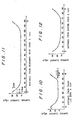
- Figure 11 shows a distribution of surface currents along the roof of the vehicle body while Figure 12 illustrates a distribution of surface currents along the engine hood of the vehicle body. Studying such distributions of surface currents with the magnitude and orientation of the surface currents shown in Figures 8 and 9, it is understood that the surface high-frequency currents flow concentratedly on the vehicle body in directions parallel to the marginal edges of the roof and engine hood with the level thereof decreasing toward the central portions thereof.
- the surface high-frequency currents similarly flow concentratedly along the connections between the respective flat portions on the vehicle body, such as pillars supporting the roof panel, trunk hinges and others.
- the surface currents flow on the pillar portions with densities equal to or higher than those of the other vehicle portions. This tendency increases as the frequency increases.
- the antenna system can detect surface currents on the pillars which could not provide any practical antenna outputs for AM frequency bands.
- the first embodiment of the present invention utilizes a first high-frequency pick-up disposed on the right or left side of the roof of the vehicle body at its rearward edge and extending along the length of the rearward edge and a second high-frequency pick-up positioned on a front pillar of the vehicle body at the same side of the vehicle body as the first high-frequency pick-up and extending along the length of the pillar.
- the sensitivity of the first high-frequency pick-up is higher in the rightward and longitudinal directions of the vehicle body while the second high-frequency pick-up has its higher sensitivity in the rightward and leftward directions of the vehicle body.
- the sensitivity of the first pick-up is higher in the leftward and longitudinal directions of the vehicle body while the sensitivity of the second pick-up is higher in the rightward and leftward directions of the vehicle body.
- the two high-frequency pick-ups have FM band directional patterns so formed that one of the pick-ups will complement the sensitivity of the other pick-up which is lower than that of said one pick-up, and yet these pick-ups are spatially spaced longitudinally from each other. Therefore, a good space diversity can effectively be attained by changing reception, from one to other of the pick-ups.
- the high-frequency pick-up for example, a loop antenna is disposed in close proximity to the marginal edge of any vehicle portion, it is preferred that the pick-up is spaced from that marginal edge within a range depending on the carrier frequency of radio or other waves to be received to provide very good sensitivity.
- Figures 10 to 12 illustrate distributions of surface currents induced on the vehicle body by FM radio waves having a frequency equal to 80 MHz.
- the value of the surface currents decreases from the edge or end toward the central portion of the vehicle body.
- the level of the surface currents decreased below 60 dB which is a lower limit for actually obtaining good sensitivities, it is understood that if the pick-up is located at a location spaced from the edge portion within a distance of 4.5 cm, very good sensitivities can be obtained.
- the antenna system according to the present invention is sufficiently practicable if its high-frequency pick-ups are spaced from the marginal edge of any vehicle portion within a range of 4.5 cm.
- the pick-up may be disposed on the vehicle portion at a location spaced from the marginal edge thereof within a range of 3.6 cm for the carrier frequency equal to 100 MHz. As the level of the carrier frequency increases, the high-frequency pick-up should be located nearer the marginal edge of the vehicle portion.
- the high-frequency pick-up When the high-frequency pick-up is mounted on a connection between flat vehicle panels, for example, a pillar or trunk hinge, said spacing may not be considered.
- the high-frequency pick-up may merely be disposed in close proximity to that connection and parallel to the length thereof to detect radio or other waves more sensitively.
- the high-frequency pick-ups having their directional patterns different from each other are combined to form a diversity receiving system which can always receive radio or other waves more sensitively.
- first high-frequency pick-up 32 mounted on the rightward and rearward edge of a roof panel 34 and extending parallel to the length of the rearward edge and a second high-frequency pick-up 36 mounted on a rightward and forward pillar 38 and extending parallel to the length thereof.
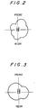
- Figure 2 shows the FM band directional pattern in the first high-frequency pick-up 32.
- the first high-frequency pick-up 32 has its sensitivity increased in the rightward and longitudinal directions with respect to the vehicle body.
- the second high- fequency pick-up 36 has its sensitivity increased in the rightward and leftward directions with respect to the vehicle body.
- the first and second high-frequency pick-ups 32 and 36 are spaced from each other a distance of about 1.5 meters to about 1.8 meters in the longitudinal direction of the vehicle body. Since the wavelength of FM radio waves is in the order of 3.0 meters, the antenna system including such a combination of the high-frequency pick-ups 32 and 36 can make the space diversity very effective.
- both the first and second high-frequency pick-ups 32 and 36 are located on the rightward side of the vehicle body.
- the present invention permits these pick-ups 32 and 36 to be disposed on the left side of the vehicle body.
- the directional patterns of the first and second high-frequency pick-ups 32 and 36 are completely inverse in the leftward and rightward directions in comparison with those shown in Figures 2 and 3.
- the complement between the first and second pick-ups provides the same advantages as in the first embodiment.
- each of the first and second high-frequency pick-ups 32 and 36 has its output connected to a high-frequency amplifying circuit 42 through a switching circuit 40 via a coaxial cable.
- the switching circuit 40 is actuated on receiving a signal from the output of a T-shaped flip flop 44.
- the switching circuit 40 When the switching circuit 40 is actuated, the outputs of the first and second high-frequency pick-ups 32 and 36 are selectively coupled to the input of the high-frequency amplifying circuit 42.
- the output of the high-frequency amplifying circuit 42 is connected to an intermediate frequency amplifying circuit 48 which is in turn connected to a local oscillator circuit 46 and also a detector circuit 50 from which only voice signals are provided.
- the voice signals are divided into right-hand and left-hand outputs through a multiplexer 52, which outputs are then supplied respectively to right-hand and left-hand amplifiers 54R and 54L.
- the amplified right- and left-hand voices are then reproduced by right- and left-hand speakers 56R and 56L.
- the output signals from the intermediate frequency amplifying circuit 48 are compared with its threshold at a comparator 58 which is adapted to generate a trigger output used for inverting the T-shaped flip flop 44 if the sensitivities of both the high-frequency pick-ups 32 and 36 are reduced below a predetermined level.
- the inversion of output in the flip flop 44 causes the switching circuit 40 to change one of the high-frequency pick-ups 32 and 36 to the other which has a better sensitivity.
- a space diversity reception type antenna system in which the first high-frequency pick-up 32 on the rear of the roof panel 34 and the second high-frequency pick-up 36 on the front pillar are complemented by each other with respect to their directional patterns to render the antenna system more sensitive at all times.
- the roof panel 34 as uncovered, which includes a rear window frame 60 formed thereon at the marginal edge.
- the rear window frame 60 is in turn provided with a rear window glass 62.
- the high-frequency pick-up 32 includes a metallic casing 64 for shielding external magnetic fluxes and a loop antenna 66 mounted in the casing 64, all of which forms an electromagnetic coupling type pick-up having a structure similar to that of the aforementioned probe including the loop coil used to determine the distribution of surface currents on the vehicle body.
- FIG 15 shows the mounting of the high-frequency pick-up 32 on the roof panel 34.
- the roof panel 34 includes a rear portion 68 on which the rear window frame 60 is fixedly mounted at one edge.
- the rear portion 68 also fixedly supports the rear glass 62 through fastener means 70 and dam means 72 which are air-tightly secured to each other through adhesive 74.
- a molding 76 is mounted between the roof panel 68 and the rear window glass 62.
- a roof garnish 88 is fixedly mounted on the roof panel 68 inside the rear window frame 60.
- the marginal edges of the roof garnish 88 and rear window frame 60 are covered by an edge molding 90.
- the edge molding 90 is supported by an elongate edge molding support 92 located between the rear window frame 60 and the roof garnish 88.
- the support 92 is separated from the rear window frame 60 by spacers 94 and 96.
- the rear window frame 60 is provided with an opening 60a within which the casing 64 of the high-frequency pick-up 32 is positioned to arrange a loop antenna 66 in the high-frequency pick-up 32 in close proximity to the marginal edge of the support 92.
- loop antenna 66 of the high-frequency pick-up 32 is disposed in close proximity to the marginal edge of the support 92 along the length thereof.
- the sensitivity of the high-frequency pick-up 32 can further be improved.
- the casing 64 of the high-frequency pick-up 32 includes an opening 64a formed therein, through which one of the longer sides of the loop antenna 66 is externally exposed.
- the exposed portion of the loop antenna 66 is disposed in close proximity to the marginal edge of the support 92.
- the loop antenna 66 as located within the casing 64 can positively catch a magnetic flux formed by surface high-frequency currents flowing on the marginal edge of the support 92.
- any external magnetic fluxes other than the magnetic flux caught by the loop antenna 66 can positively be shielded by the casing 64. Therefore, the surface currents induced on the vehicle body by radio or other waves can more sensitively be detected by the high-frequency pick-up 32.
- L-shaped brackets 78 and 80 are respectively connected with the opposite ends of the casing 64 by any suitable fastening means such as bolts. These brackets 78 and 80 are then fastened to the rear window frame 60 as by screws so that the casing 64 of the high-frequency pick-up 32 can positively be fastened to the edge molding support 92.
- the casing 64 of the high-frequency pick-up 32 contains circuitry 82 electrically connected to the loop antenna 66.
- the circuitry 82 includes various circuits for processing signals, such as pre-amplifier and others. The processed signals are fed externally through a coaxial cable 84 and then processed by circuits similar to those used to determine the distribution of surface currents on the vehicle body.
- the circuitry 82 receives power and control signals through a cable 86.
- the loop antenna 66 is in the form of a single-winding antenna the winding of which is covered with an insulating coating such that the loop antenna 66 can be electrically insulated from and positioned in close proximity to the support 92. This permits the loop antenna 66 to intersect a magnetic flux formed by the surface currents on the vehicle body.
- the exposed portion of the loop antenna 66 outside the casing 64 is spaced from the marginal edge of the elongate support 92 within a distance of 4.5 cm. Therefore, the high-frequency pick-up 32 can positively detect radio waves having particularly a frequency of 50 to 300 M Hz from the surface currents flowing on the marginal edge of the support 92. Since the orientation of the surface currents is along the marginal edge of the support as shown in Figure 9, the exposed portion of the loop antenna 66 is preferably disposed parallel to the marginal edge of the support 92.
- the second high-frequency pick-up 36 is mounted within one of the front pillars 38 for supporting the roof panel of the vehicle body.
- the second high-frequency pick-up 36 is similarly in the form of an electromagnetic coupling type pick-up including a loop antenna.
- the front pillar 38 includes a pillar leg plate 136 which provides a main hollow column of quadrilateral configuration.
- the outer side of the pillar leg plate 136 supports a windshield molding 138 which in turn supports a windshield glass 140.
- the rearward side of the pillar leg plate 136 supports a weather strip 142 of rubber for water-tightly sealing between the pillar leg plate 136 and a side glass 144.
- the inner side of the pillar leg plate 136 is covered by a front pillar garnish 146 giving the pillar leg plate 136 an aesthetic appearance.
- the second high-frequency pick-up 36 is disposed parallel to the length of the front pillar 38, and is mounted within the interior of the pillar leg plate 136.
- the high-frequency pick-up 36 comprises a casing 148 of electrically conductive material and a loop antenna 150 mounted within the casing 148 such that the loop antenna 150 can be shielded from external magnetic fields.
- the casing 148 is provided with an opening 148a through which a portion of the loop antenna 150 is externally exposed. The exposed portion of the loop antenna 150 is thus disposed in close proximity to the pillar leg plate 136 on which the surface high-frequency currents flow concentratedly.
- the pillar leg plate 136 is provided with an opening 136a through which the high-frequency pick-up 36 is inserted into the interior of the pillar leg plate 136 before a front pillar garnish 146 is mounted on the pillar leg plate 136.
- the casing 148 of the high-frequency pick-up 36 includes brackets 152 and 154 fastened to the opposite end thereof as by spot-welding. These brackets 152 and 154 are in turn fastened to the pillar leg plate 136 as by screws, as shown.
- the loop antenna 150 is disposed in close proximity to the edge of the opening 136a in the pillar leg plate 136. As a result, a magnetic flux formed by the surface high-frequency currents flowing concentratedly on the pillar leg plate 136 can more efficiently intersect the loop antenna 150.
- the casing 148 also contains circuitry 156 including pre-amplifier means and others which is located behind the loop antenna 150 within the casing 148.
- the circuitry 156 is supplied with power and control signals through a cable 158. Signals acquired by the loop antenna 150 are fed externally through a coaxial cable 160 and then processed by circuits similar to those used to determine the distribution of surface currents on the vehicle body as described hereinbefore.
- the loop antenna 150 is similarly in the form of a single-winding coil which is covered with an electrical insulation coating such that the coil can electrically be insulated from and disposed in close proximity to the pillar leg plate 136.
- the front pillar garnish 146 After the high-frequency pick-up 36 has been mounted in the front pillar 38, the latter is covered by the front pillar garnish 146 to provide an ordinary appearance which is not different from the conventional pillar construction.
- the first embodiment provides a space diversity reception automobile antenna system which can efficiently receive radio or other waves, with less noise, from the surface high-frequency currents flowing on the marginal edges of the rear roof and front pillar and yet which is small-sized without any externally exposed portion such as pole antenna and others.
- the second embodiment of the present invention is described in relation to Figures 19 to 24 and utilizes a pair of high-frequency pick-ups located respectively on the trunk lid and on one of the front pillars of the vehicle body wherein the density of surface currents induced on the vehicle body by radio or other waves is higher with less noise.
- the first high-frequency pick-up is disposed on the central portion of the trunk lid of the vehicle body near the inner edge thereof and extending parallel to the length of the inner edge.
- the second high-frequency pick-up is located on one of the front pillars on the vehicle body and extends parallel to the length of the front pillar.
- One of the first and second high-frequency pick-ups is automatically selected to receive radio or other waves more sensitively.
- the space diversity automobile antenna system including the first and second high-frequency pick-ups arranged as just mentioned is similarly effective to receive radio or other waves more sensitively.
- Figure 19 shows the FM band directional pattern of the first high-frequency pick-up 32' mounted on the trunk lid 34'.
- the first high-frequency pick-up 32' has its sensitivity increased in the longitudinal direction with respect to the vehicle body.
- Figure 20 shows the FM band directional pattern of the second high-frequency pick-up 36' mounted on the forward and rightward pillar 38' of the vehicle body.
- the second high-frequency pick-up 36' has its sensitivity increased in the rightward and leftward directions with respect to the vehicle body.
- FM radio waves can more efficiently be received by the fact that the directional pattern of one of the two high-frequency pick-ups will be complemented by that of the other pick-up.
- the first and second high-frequency pick-ups 32' and 36' are spaced from each other a distance equal to about 2 meters in the longitudinal direction of the vehicle body. Since the wavelength of FM waves is equal to about 4 meters, the space diversity is very advantageous for FM wave bands with S/N ratio being improved.
- the second embodiment has been described as to the second high-frequency pick-up 36' mounted on the forward and rightward pillar 38' of the vehicle body, it may alternatively be mounted on the forward and leftward pillar of the vehicle body, with the same advantages.
- a circuit which is effective to automatically change one of the first and second high-frequency pick-ups 32' and 36' such that radio or other waves can be received more sensitively by the selected pick-up, is similar to that of the first embodiment shown in Figure 1 and therefore not further described herein.
- the first high-frequency pick-up 32' mounted on the marginal edge of the trunk lid 34' is in the form of an electromagnetic coupling type pick-up similar to the aforementioned probe which includes the loop coil used to determine the distribution of surface currents on the vehicle body.
- the trunk lid 34' is pivotally connected at one edge with the vehicle body through trunk hinges 60'.
- a weather strip 64' for water-tightly sealing between the trunk lid 34' and a rear tray panel 62' so that any external water can be prevented from penetrating into the interior of the vehicle body through a rear window glass 66'.
- a dam 68' air-tightly seals between the rear window glass 66' and the rear tray panel 62' to prevent rain, external noise and others from penetrating into the interior of the vehicle body. Further, a molding 70' is provided to cover the lower edge of the rear window glass 66', as Well-known in the art.
- the first high-frequency pick-up 32' faces the rear tray panel 62' on the central portion of the marginal edge of the trunk lid 34' such that the length of a loop antenna 72' in the high-frequency pick-up 32' will extend parallel to the marginal edge of the trunk lid 34'.
- the loop antenna 72' can detect the surface currents on the trunk lid with less noise.
- the loop antenna 72' When the loop antenna 72' is to receive FM radio waves having a frequency equal to 80 MHz, it is preferably spaced from the marginal edge of the trunk lid 34' within a range defined by the aforementioned formula: that is, within a distance of 4.5 cm. Thus, the loop antenna 72' can positively and efficiently catch the surface currents flowing concentratedly on the marginal edge portion of the trunk lid 34'.
- the loop antenna 72' is arranged such that the length thereof is parallel to the marginal edge of the trunk lid 34'.
- the first high-frequency pick-up 32' comprises a casing 48' of electrically conductive material within which the loop antenna 72' and associated circuit section 76' including a pre-amplifier and others are housed.
- the casing 74' is provided with an opening 74a facing the trunk lid 34'.
- the loop antenna 72' housed within the casing 74' can catch only magnetic flux formed by the surface high-frequency currents flowing on the marginal edge of the trunk lid 74' while at the same time any undesirable and external flux can positively be shielded by the casing 74'.
- the loop antenna 72' is in the form of a single-winding coil located along the turned edge of the trunk lid 34', which coil is covered with an insulating layer such that it can electrically be insulated from and located in close proximity to the trunk lid 34'.
- a magnetic flux formed by the surface currents can efficiently intersect the loop antenna 72'.
- the circuit 76' is supplied with power and control signals through a cable 78'. Signals received by the loop antenna 72' are externally fed through a coaxial cable 80' and then processed by circuits similar to those used to determine the distribution of surface currents on the vehicle body.
- fittings 82' are fastened to the opposite ends of the casing 74' of the high-frequency pick-up 32' as by bolts.
- Each of the fittings 82' is in turn fastened to the trunk lid 34' by screws 84'.
- the high-frequency pick-up 32' can firmly be mounted on the inside of the trunk lid 34'.
- the second high-frequency pick-up 36' is housed within a front pillar of the vehicle body in the same manner as the pick-up 36 described in the first embodiment in relation to Figures 16 to 18.
- the second embodiment provides a space diversity reception automobile antenna system which can efficiently receive radio or other waves, with less noise, from the surface high-frequency currents flowing on the trunk lid and front pillar and yet which is small-sized without any externally protruding portion such as pole antenna and others.
- the third embodiment is described in relation to Figures 25 to 31 and utilizes a pair of high-frequency pick-ups which are located on the roof panel of the vehicle body near the marginal edge thereof and spaced from each other a predetermined distance.
- surface high-frequency currents flow concentratedly on the marginal edge of the roof panel on the vehicle body.
- the high-frequency pick-ups mounted on the roof panel can efficiently detect the surface high-frequency currents flowing on the marginal edge of the roof panel.
- One of the high-frequency pick-ups is automatically changed to the other such that radio or other waves can tie received by the antenna system more sensitively.
- the directional pattern of the antenna system may be improved with less multi-path noise.
- FIG. 25 to 28 there is shown one of the high-frequency pick-ups 238 which is mounted on the marginal edge portion of the roof panel adjacent to the rear window glass 236.
- Figure 25 shows the roof panel 232 of metal material as uncovered, which is connected with the rear window glass 236 through a rear window frame 234.
- the high-frequency pick-up 238 is spaced inwardly from the marginal edge of the rear window frame 234 within a range of 4.5 cm.
- the high-frequency pick-up 238 comprises a casing 240 of metal material for shielding any external undesired flux and a loop antenna 242 housed within the casing 240.
- the high-frequency pick-up 238 is similarly in the form of an electromagnetic coupling type pick-up similar to the aforementioned probe which includes the loop coil used to determine the distribution of surface currents on the vehicle body.
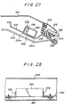
- FIG 27 shows the mounting of the high-frequency pick-up 238 on the roof panel 232.
- the roof panel 232 includes a roof panel portion 244 to which the rear window frame 234 is secured at one edge.
- the roof panel 244 also supports the rear window glass 236 through fastening means 246 and dam means 248 which are air-tightly fastened to each other by adhesive 250.
- a molding 252 is mounted between the roof panel portion 244 and the rear window glass 236.
- the rear window frame 234 is provided with an opening 234a through which the high-frequency pick-up 238 is inserted into the rear window frame 234 such that the loop antenna 242 of the high-frequency pick-up 238 will be positioned faced to the marginal edge of the rear window frame 234.
- the casing 240 is provided with an opening 240a through which one of the longitudinal sides of the loop antenna 242 is externally exposed.
- the exposed portion of the loop antenna 242 is disposed in close proximity to the edge of the opening 234a in the rear window frame 234.
- a magnetic flux formed by the surface high-frequency currents flowing on the marginal edge portion of the rear window frame 234 can positively be caught by the loop antenna 242 within the casing 240.
- any external and undesirable waves can positively be blocked by the casing 240. Therefore, the surface currents induced on the vehicle body by radio or other waves can be detected by the high-frequency pick-up 238 more sensitively.
- L-shaped brackets 254 and 256 are fastened to the casing 240 at the opposite ends thereof as by bolts.
- the brackets 254 and 256 also are fastened to the rear window frame 234 by means of screws.
- the high-frequency pick-up 238 may positively be fastened to the rear window frame 234.
- the casing 240 of the high-frequency pick-up 232 also includes circuitry 258 housed in the casing 240 and electrically connected to the loop antenna 242. Detected signals are processed by pre-amplifier means and others in the circuitry 258. The processed signals are externally fed through a coaxial cable 260 and then processed by circuits similar to those used in determining the distribution of surface currents on the vehicle body.
- the circuitry 258 is supplied with power and control signals through a cable 262.
- the loop antenna 242 is similarly in the form of a single-winding coil which is covered with an electrically insulating coating such that it can be electrically insulated from and positioned in close proximity to the rear window frame 234. As a result, a magnetic flux formed by the surface currents on the vehicle body may effectively intersect the loop antenna 242.
- a roof garnish 264 is fastened to the roof panel.
- An edge molding 266 is then mounted between the roof garnish 264 and the rear window frame 234.
- the exposed portion of the loop antenna 242 out of the casing 240 is spaced from the marginal edge of the rear window frame 234 within a distance of 4.5 cm. Therefore, the high-frequency pick-up 238 can positively receive radio or other waves having a frequency equal to 80 MHz from the surface currents flowing on the marginal edge portion of the rear window frame 234. Since the orientation of the surface currents is along the marginal edge of the vehicle body as shown in Figure 9, the loop antenna 246 should be arranged such that the length thereof will extend parallel to the marginal edge of the rear window frame 234.
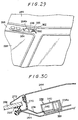
- the other high-frequency pick-up 338 is mounted on the roof panel 232 near the forward edge thereof, as shown in Figures 29 and 30.
- the high-frequency pick-up 338 is disposed within the service hole 264a in the header inner panel 264 which is provided on the forward edge of the roof panel 232.
- a windshield glass 268 is connected to a roof panel portion 244 through a dam 266.
- a molding 272 is mounted between the roof panel portion 244 and the windshield glass 268 through a stopper 270.
- the high-frequency pick-up 338 is similar to the high-frequency pick-up 238. Parts similar to those of the high-frequency pick-up 238 are denoted by similar reference numerals increased by one hundred. As seen from Figure 30, a loop antenna 342 in the high-frequency pick-up 338 is spaced inwardly from the marginal edge of the header inner panel 225 within a distance of 4.5 cm. Therefore, surface current flowing concentratedly on the header inner panel 264 can positively be detected by this high-frequency pick-up 338.
- the two high-frequency pick-ups 238 and 338 are spaced from each other a distance meeting the spacing between two antennas which should be equal to A/2 in a diversity receiving system for FM band having its wavelength equal to about 3 meters. In the third embodiment, this spacing is set to be in the order of 1.8 to 1.5 meters.
- a circuit for automatically selecting one of the two high-frequency pick-ups 238 and 338 which may receive signals more sensitively at that time has been described in relation to Figure 1.
- the sensitivities of the high-frequency pick-ups 238 and 338 may be complemented by one another to improve their directional patterns, as shown in Figure 31, and also to reduce multi-path noise.
- a pair of high-frequency pick-ups 438 and 538 may be mounted on the roof panel 232 near the marginal edge of the rear window glass. Furthermore, these high-frequency pick-ups 438 and 538 a re spaced from each other within a range meeting such a condition that the spacing between two antennas should be below M2 in the diversity receiving system when FM band having a wavelength A equal to about 3 meters is to be received by the antenna system. In the third embodiment, the two high-frequency pick-ups 438 and 538 are spaced from each other a distance equal to about 1 to 1.2 meters. Their directional patterns are shown in Figure 32.
- the third and fourth embodiments provide space diversity reception automobile antenna systems comprising a pair of high-frequency pick-ups for efficiently detecting surface currents induced on the roof panel of the vehicle body by radio or other waves and flowing concentratedly on the marginal edge of the roof panel and which have an improved directional pattern with less multi-path noise.
- the fifth embodiment utilizes a pair of high-frequency pick-ups 1032 and 1132 which are mounted in the front pillars 1034 and 1134 of the vehicle body supporting the roof panel thereof, respectively.
- Each of these high-frequency pick-ups 1032 and 1132 is similarly in the form of an electromagnetic coupling type pick-up.
- the high-frequency pick-ups 1032 and 1132 are each mounted in a respective one of the front pillars 1034 in the same manner as the pick-up 36 described in the first embodiment in relation to Figures 16 to 18.
- the front pillars 1034 and 1134 are spaced from each other a distance of about 1.8 meters to about 1.5 meters.
- two high-frequency pick-ups 1032 and 1132 mounted in the front pillars 1034 and 1134 can provide an excellent antenna system of space diversity receiving type.
- a circuit effective to automatically select one of the two high-frequency pick-ups 1032 and 1132 such that radio or other waves can more efficiently be received by the selected pick-up, has been described in relation to Figure 1.
- the directional pattern of one of the high-frequency pick-ups 1032 and 1132 will be complemented by that of the other high-frequency pick-up to improve the entire sensitivity of the antenna system with less multi-path noise.
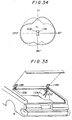
- the sixth embodiment of the present invention utilizes a pair of high-frequency pick-ups 1232 and 1332 which are mounted on two trunk hinges 1086 and 1186 of the vehicle body.
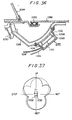
- Each of these high-frequency pick-ups 1232 and 1332 is similarly in the form of an electromagnetic coupling type pick-up. Since the high-frequency pick-ups 1232 and 1332 have the same construction and function, only one of them 1232 will be described below with reference to Figure 36.
- the trunk hinge 1086 is pivotally connected at one end with the vehicle body with the other end thereof being rigidly connected with the trunk lid 1088.
- the pivot end of the trunk hinge 1086 is provided with a torsion bar 1090 for absorbing an impact when the trunk lid 1088 is opened.
- a weather strip 1092 is provided to water-tightly seal between the vehicle body and the trunk lid 1088 to prevent rain from penetrating into the vehicle body through a rear window glass 1094.
- the high-frequency pick-up 1232 is rigidly mounted on the outer or trunk-room side of the trunk hinge 1086 and extends parallel to the length thereof.
- a loop antenna 1096 in the high-frequency pick-up 1232 will be disposed so that the longitudinal portion thereof extends parallel to the length of the trunk hinge 1086.
- the loop antenna 1096 can positively and efficiently catch surface currents flowing on the trunk hinge 1086.
- the high-frequency pick-up 1232 comprises a casing 1098 of electrically conductive material in which the loop antenna 1096 and associated circuitry 1100 are mounted.
- the casing 1098 is provided with an opening facing the trunk hinge 1086.
- L-shaped fittings 1102 and 1104 are fastened to the opposite ends of the casing 1098 and also rigidly connected to the trunk hinge 1086 by means of screws
- the loop antenna 1096 in the casing 1098 can catch only a magnetic flux formed by the surface high-frequency currents flowing on the trunk hinge 1086 and also shielded from other external undesired fluxes.
- the loop antenna 1096 is preferably curved to be compatible with the curvature of the trunk hinge 1086.
- the circuitry 1100 is supplied with power and control signals through a cable 1106. Signals received by the loop antenna 1096 are externally fed through a coaxial cable 1108 and then suitably processed by circuits similar to those used in determining the distribution of surface currents on the vehicle body.
- the loop antenna 1096 is similarly in the form of a single-winding coil which is covered with an electrical insulation coating such that the coil can be electrically insulated from and located in close proximity to the trunk hinge 1086. As a result, a magnetic flux formed by the surface currents can efficiently intersect the loop antenna 1096.
- a circuit effective to automatically select one of the two high-frequency pick-ups 1232 and 1332 such that radio or other waves can be received more sensitively by the selected pick-up is similar to that described in relation to Figure 1.
- the space diversity reception antenna system including the high-frequency pick-ups 1232 and 1332 is very advantageous in sensitivity with less multi-path noise, for FM radio waves having a wavelength equal to about 4 meters. As seen from Figure 37, this is due to the fact that the directional patterns of the high-frequency pick-ups 1232 and 1332 are symmetrical relative to each other about the longitudinal axis of the vehicle body.
- the sixth embodiment of the present invention provides a space diversity reception automobile antenna system comprising a pair of high-frequency pick-ups disposed to detect surface currents induced on the vehicle body and flowing concentratedly on the trunk hinges thereof and which has an improved directional pattern with less multi-path noise.
- the seventh embodiment of the present invention is described in relation to Figures 38 to 42 and utilizes a pair of high-frequency pick-ups which are mounted on either the trunk lid or on the engine hood of the vehicle body at locations spaced from each other a predetermined distance or alternatively one on each of the trunk lid and the engine hood.
- Each of the high-frequency pick-ups is positioned near the marginal edge of the above vehicle portion on which surface currents induced by radio or other waves flow concentratedly as previously described in connection with Figures 8 to 12.
- Figure 44 shows a distribution of noise currents on the vehicle body along the transverse line G-H shown in Figure 8. As seen from this Figure, the level of noise currents decreases at the center and ends of the transverse line G-H. If a high-frequency pick-up is located on the trunk lid at one of the center and sides thereof, therefore, the surface high-frequency currents can be detected by this high-frequency pick-up with less noise.
- Figure 45 shows a distribution of noise currents on the engine hood along the section E-F of the longitudinal line shown in Figure 8. As seen from this Figure, the level of the noise currents is minimum at the opposite ends of the section E-F.
- the high-frequency pick-up is preferably located on one of the four corners of the engine hood or the center of the inner edge of the engine hood since it can more efficiently detect the surface high-frequency currents flowing concentratedly thereon with less noise.
- the high-frequency pick-up 2032 is of the electromagnetic coupling type similar to the probe including the loop coil used in determining the distribution of surface currents on the vehicle body and is mounted on the trunk lid near the inner edge thereof in the same manner as the pick-up 32' described in relation to Figures 21 to 24.
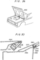
- Figures 38 to 41 show the other high-frequency pick-up 2132 which is mounted on the engine hood of the vehicle body.
- the engine hood 2060 is pivotally connected at one edge to the vehicle body.
- the marginal edge thereof on the side of a windshield glass 2062 faces a front outer panel 2064.
- the edge of the front outer panel 2064 facing the side of the passenger room is connected to a front inner panel 2066.
- the windshield glass 2062 is supported on the front outer panel 2064 by a stopper 2068.
- a dam 2070 is provided between the windshield glass 2062 and the front inner panel 2066 to prevent any external water such as rain from penetrating into the vehicle body.
- the lower edge of the windshield glass 2062 is covered by a molding 2072 as well-known in the art.
- the high-frequency pick-up 2132 is similar to the high-frequency pick-up 2032 and thus also to pick-up 32' described in relation to Figures 21 to 24.
- the high-frequency pick-up 2132 is spaced from the inner edge of the engine hood 2060 inwardly within a range of 4.5 cm. Therefore, this high-frequency pick-up 2132 can positively detect the surface high-frequency currents flowing concentratedly on the marginal edge of the engine hood with less noise.
- Figure 40 shows the mounting of the high-frequency pick-up 2132 on the engine hood 2060 while Figure 41 illustrates the outline of the high-frequency pick-up 2132 mounted on the engine hood 2060.
- a circuit which is effective to automatically select one of the high-frequency pick-ups 2032 and 2132 such that radio or other waves can be received more sensitively by the selected pick-up has been described in relation to Figure 1.
- the two high-frequency pick-ups 2032 and 2132 together define a space diversity reception antenna which can always receive radio or other waves more sensitively.
- this is due to the fact that the directional pattern of one of the high-frequency pick-ups 2032 and 2132 can be complemented by that of the other high-frequency pick-up.
- the diversity receiving system reduces multi-path noise.
- the eighth embodiment of the present invention utilizes a pair of high-frequency pick-ups 2232 and 2332 which are mounted on the trunk lid near the inner edge thereof and spaced from each other along the inner edge of the trunk lid.
- Such an arrangement has the same advantages as in the previously mentioned embodiments since the directional pattern of one of the high-frequency pick-ups can be complemented by that of the other high-frequency pick-up.
- the seventh and eighth embodiments provide improved automobile antenna systems which can operate as diversity receiving systems with improved directional pattern and with less multi-path noise. Moreover, the positions of the antenna systems facilitate their installation and maintenance.
- the ninth embodiment of the present invention utilizes a pair of high-frequency pick-ups which are located respectively on a front pillar and a trunk hinge.
- the diversity reception automobile antenna system will not be changed in antenna characteristics even when the wiper device is actuated and can provide an improved diversity effect without any externally extending portion.
- FIGS 52 and 53 there are shown the magnitude and orientation of surface high-frequency currents induced on the vehicle body at various locations by radio or other waves having a frequency of 80 MHz and determined by a simulation by computer and actual measurements by the aforementioned probe P.
- the magnitude of the surface currents is higher along the marginal edge of each of flat vehicle portions and very low at the center thereof.
- the surface currents concentrate their flow parallel to the marginal edge of each vehicle portion and along the connections between each adjacent portion of flat configuration.
- One of the high-frequency pick-ups 3032 is mounted on the front right-hand pillar in the same manner as the pick-up 36 described in relation to Figures 16 to 18.
- the trunk hinge is remote from the engine and not very influenced by noise, detected currents can provide signals which are superior in quality and S/N ratio.
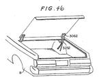
- the other high-frequency pick-up 3232 is mounted on one of the trunk hinges 3062, as shown in Figure 46, and in the same manner as described in relation to Figure 36.
- Figure 47 shows a circuit (similar to Figure 1) which is effective to automatically select one of the high-frequency pick-ups 3032 and 3232, which are mounted respectively on the front pillar and trunk hinge 3034, 3062, such that radio or other waves can be received by the selected pick-up more sensitively.
- a switching circuit 3086 is electrically connected to both the high-frequency pick-ups 3032 and 3232.
- the switching circuit 3086 is actuated on receiving output signals from a T-shaped flip flop 3088 which will be described as a conditioning circuit.
- one of the high-frequency pick-ups 3032 and 3232 is selected with its output signal being supplied to an intermediate frequency amplifier circuit 3092 through a high-frequency amplifier circuit 3090.
- Output signals from the intermediate frequency amplifier circuit 3092 are supplied to a detector circuit 3094 from which only voice signals are fed. Voice signals are then supplied to a speaker 3098 through an amplifier 3096.
- Output signals from the intermediate frequency amplifying circuit 3092 are detected with respectto their level by a level detector 3100.
- a subsequent level comparator 3102 is set to have a threshold indicative of an output signal from the intermediate frequency amplifying circuit 3092 if either of the high-frequency pick-up 3032 or 3232 has its sensitivity lowered below a predetermined level.
- the level of the output signal from the level detector 3100 is compared with said threshold at the level comparator 3102. If the level is smaller than said threshold, the level comparator 3102 then generates a trigger signal which in turn is supplied to the T-shaped flip flop 3088. Therefore, the output ofthe T-shaped flip flop 3088 is inverted to actuate the switching circuit 3086.
- one of the high-frequency pick-ups 3032 and 3232 is selected such that radio or other waves can be received by the selected pick-up more sensitively. Received signals are then supplied to the high-frequency amplifying circuit 3090.
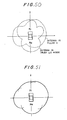
- the high-frequency pick-up 3032 mounted on the front pillar 3034 has a directional pattern as shown in Figure 48 while the high-frequency pick-up 3232 on the trunk hinge 3062 has a directional pattern as shown in Figure 49.
- the high-frequency pick-ups 3032 and 3232 complement each other with respect to sensitivity to improve the directivity of the antenna system.
- the high-frequency pick-up 3032 on the front pillar 3034 is remote from the wiper blades (not shown). When the wiper is operated, therefore, the characteristics of the high-frequency pick-up 3032 will not adversely be affected by the motion of the wiper.
- the automobile antenna system is not subject to being damaged or stolen since it does not need to use any externally extending member such as a pole antenna.
Landscapes
- Engineering & Computer Science (AREA)
- Computer Networks & Wireless Communication (AREA)
- Signal Processing (AREA)
- Details Of Aerials (AREA)
Claims (16)

Priority Applications (1)
| Application Number | Priority Date | Filing Date | Title |
|---|---|---|---|
| AT85308293T ATE60467T1 (de) | 1984-11-15 | 1985-11-14 | Kraftfahrzeugantennensystem. |
Applications Claiming Priority (12)
| Application Number | Priority Date | Filing Date | Title |
|---|---|---|---|
| JP242097/84 | 1984-11-15 | ||
| JP59242097A JPS61120503A (ja) | 1984-11-15 | 1984-11-15 | 車両用アンテナ装置 |
| JP251243/84 | 1984-11-27 | ||
| JP59251243A JPS61128608A (ja) | 1984-11-27 | 1984-11-27 | 自動車用アンテナ装置 |
| JP59252285A JPS61129906A (ja) | 1984-11-28 | 1984-11-28 | 車両用アンテナ装置 |
| JP252285/84 | 1984-11-28 | ||
| JP258950/84 | 1984-12-07 | ||
| JP59258950A JPS61159806A (ja) | 1984-12-07 | 1984-12-07 | 自動車用アンテナ装置 |
| JP60143094A JPS623507A (ja) | 1985-06-28 | 1985-06-28 | 自動車用アンテナ装置 |
| JP60143089A JPS623502A (ja) | 1985-06-28 | 1985-06-28 | 自動車用アンテナ装置 |
| JP143089/85 | 1985-06-28 | ||
| JP143094/85 | 1985-06-28 |
Publications (2)
| Publication Number | Publication Date |
|---|---|
| EP0183443A1 EP0183443A1 (fr) | 1986-06-04 |
| EP0183443B1 true EP0183443B1 (fr) | 1991-01-23 |
Family
ID=27552964
Family Applications (1)
| Application Number | Title | Priority Date | Filing Date |
|---|---|---|---|
| EP85308293A Expired EP0183443B1 (fr) | 1984-11-15 | 1985-11-14 | Système d'antenne pour véhicule automobile |
Country Status (5)
| Country | Link |
|---|---|
| US (1) | US4811330A (fr) |
| EP (1) | EP0183443B1 (fr) |
| CA (1) | CA1254654A (fr) |
| DE (1) | DE3581502D1 (fr) |
| DK (1) | DK525285A (fr) |
Families Citing this family (15)
| Publication number | Priority date | Publication date | Assignee | Title |
|---|---|---|---|---|
| JPS6193701A (ja) * | 1984-10-13 | 1986-05-12 | Toyota Motor Corp | 自動車用アンテナ装置 |
| US4717922A (en) * | 1984-11-06 | 1988-01-05 | Toyota Jidosha Kabushiki Kaisha | Automobile antenna system |
| CA1249052A (fr) * | 1984-11-08 | 1989-01-17 | Junzo Ohe | Systeme d'antenne pour l'automobile |
| US4723127A (en) * | 1984-12-12 | 1988-02-02 | Toyota Jidosha Kabushiki Kaisha | Automobile antenna system |
| JPS61222303A (ja) * | 1985-03-27 | 1986-10-02 | Toyota Motor Corp | 自動車用アンテナ装置 |
| DE3676368D1 (de) * | 1985-06-10 | 1991-02-14 | Toyota Motor Co Ltd | Kraftfahrzeugfernsehantennensystem. |
| CA1258705A (fr) * | 1985-06-21 | 1989-08-22 | Hiroshi Kondo | Systeme d'antenne pour l'automobile |
| DE3685272D1 (de) * | 1985-06-28 | 1992-06-17 | Toyota Motor Co Ltd | Fahrzeugantennensystem. |
| JPS6231201A (ja) * | 1985-08-01 | 1987-02-10 | Dx Antenna Co Ltd | マイクロストリツプ・アンテナ装置 |
| JPH0626283B2 (ja) * | 1985-08-09 | 1994-04-06 | トヨタ自動車株式会社 | 自動車用アンテナ装置 |
| DE9116931U1 (de) * | 1991-12-04 | 1994-11-03 | Rohde & Schwarz GmbH & Co KG, 81671 München | Hochfrequenzpeiler für Kraftfahrzeuge |
| US5603107A (en) * | 1995-06-09 | 1997-02-11 | Ford Motor Company | Switching system for diversity antenna FM receiver |
| DE60029303T2 (de) * | 2000-04-28 | 2007-07-05 | Siemens Ag | Empfänger mit Antennendiversity |
| US7671803B2 (en) * | 2003-07-25 | 2010-03-02 | Hewlett-Packard Development Company, L.P. | Wireless communication system |
| EP2949514A4 (fr) * | 2013-05-31 | 2016-01-27 | Fujikura Ltd | Châssis de fenêtre |
Family Cites Families (17)
| Publication number | Priority date | Publication date | Assignee | Title |
|---|---|---|---|---|
| DE1949828A1 (de) * | 1968-10-04 | 1970-04-30 | Portenseigne Ets Marcel | Verfahren und Vorrichtung zum Empfangen radiofrequenter Signale |
| US3916413A (en) * | 1973-12-21 | 1975-10-28 | Ross Alan Davis | Remotely tuned conductive-body antenna system |
| AU7960975A (en) * | 1974-03-29 | 1976-09-30 | Lucas Electrical Co Ltd | Road vehicle radio installations |
| JPS5662403A (en) * | 1979-10-29 | 1981-05-28 | Nissan Motor Co Ltd | Antenna for automobile |
| GB2071465B (en) * | 1980-03-03 | 1984-06-27 | Pioneer Electronic Corp | Fm receiver for use with motor cars |
| JPS5944132A (ja) * | 1982-09-07 | 1984-03-12 | Toshiba Corp | 移動体用アンテナ装置 |
| US4499606A (en) * | 1982-12-27 | 1985-02-12 | Sri International | Reception enhancement in mobile FM broadcast receivers and the like |
| US4566133A (en) * | 1982-12-27 | 1986-01-21 | Commtech International | Switched diversity method and apparatus for FM receivers |
| JPS59181732A (ja) * | 1983-03-31 | 1984-10-16 | Toshiba Corp | 携帯用無線機におけるダイバ−シチ−受信方式 |
| JPH0622283B2 (ja) * | 1984-10-26 | 1994-03-23 | トヨタ自動車株式会社 | 自動車用アンテナ装置 |
| US4717922A (en) * | 1984-11-06 | 1988-01-05 | Toyota Jidosha Kabushiki Kaisha | Automobile antenna system |
| EP0181782B1 (fr) * | 1984-11-15 | 1991-01-23 | Toyota Jidosha Kabushiki Kaisha | Système d'antenne pour véhicule automobile |
| CA1239471A (fr) * | 1984-11-27 | 1988-07-19 | Junzo Ohe | Antenne pour automobile |
| US4723127A (en) * | 1984-12-12 | 1988-02-02 | Toyota Jidosha Kabushiki Kaisha | Automobile antenna system |
| JPS61265904A (ja) * | 1985-05-20 | 1986-11-25 | Toyota Motor Corp | 自動車用窓ガラスアンテナ |
| JP3145184B2 (ja) * | 1992-05-18 | 2001-03-12 | ホシザキ電機株式会社 | 冷蔵庫 |
| JPH05334826A (ja) * | 1992-05-29 | 1993-12-17 | Sony Corp | 磁気ヘッド |
-
1985
- 1985-11-13 CA CA000495211A patent/CA1254654A/fr not_active Expired
- 1985-11-14 EP EP85308293A patent/EP0183443B1/fr not_active Expired
- 1985-11-14 DK DK525285A patent/DK525285A/da not_active Application Discontinuation
- 1985-11-14 DE DE8585308293T patent/DE3581502D1/de not_active Expired - Lifetime
- 1985-11-14 US US06/798,024 patent/US4811330A/en not_active Expired - Lifetime
Also Published As
| Publication number | Publication date |
|---|---|
| CA1254654A (fr) | 1989-05-23 |
| DE3581502D1 (de) | 1991-02-28 |
| US4811330A (en) | 1989-03-07 |
| DK525285D0 (da) | 1985-11-14 |
| DK525285A (da) | 1986-05-16 |
| EP0183443A1 (fr) | 1986-06-04 |
Similar Documents
| Publication | Publication Date | Title |
|---|---|---|
| CA1256988A (fr) | Antenne d'automobile | |
| US4823142A (en) | Automobile antenna system | |
| US4811330A (en) | Automobile antenna system | |
| EP0182497B1 (fr) | Antenne pour véhicule automobile | |
| US4788549A (en) | Automotive antenna system | |
| US4707701A (en) | Automobile antenna system | |
| US4723127A (en) | Automobile antenna system | |
| CA1239471A (fr) | Antenne pour automobile | |
| US4821042A (en) | Vehicle antenna system | |
| US4811025A (en) | Automotive antenna system | |
| EP0180462B1 (fr) | Système d'antenne de voiture | |
| JPH053507B2 (fr) | ||
| JPH0666572B2 (ja) | 自動車用アンテナ装置 | |
| JPH0227645Y2 (fr) | ||
| JPS61120503A (ja) | 車両用アンテナ装置 | |
| JPS61174802A (ja) | 自動車用アンテナ装置 | |
| JPS61128608A (ja) | 自動車用アンテナ装置 | |
| JPS61129904A (ja) | 自動車用アンテナ装置 | |
| JPS61140201A (ja) | 自動車用アンテナ装置 | |
| JPS6237476A (ja) | 車両用キ−レスエントリ装置 | |
| JPS61159806A (ja) | 自動車用アンテナ装置 | |
| JPS61129906A (ja) | 車両用アンテナ装置 | |
| JPS623507A (ja) | 自動車用アンテナ装置 | |
| JPS623506A (ja) | 自動車用アンテナ装置 | |
| JPS623503A (ja) | 自動車用tvアンテナ装置 |
Legal Events
| Date | Code | Title | Description |
|---|---|---|---|
| PUAI | Public reference made under article 153(3) epc to a published international application that has entered the european phase |
Free format text: ORIGINAL CODE: 0009012 |
|
| AK | Designated contracting states |
Kind code of ref document: A1 Designated state(s): AT CH DE FR GB LI SE |
|
| 17P | Request for examination filed |
Effective date: 19860731 |
|
| 17Q | First examination report despatched |
Effective date: 19880511 |
|
| GRAA | (expected) grant |
Free format text: ORIGINAL CODE: 0009210 |
|
| AK | Designated contracting states |
Kind code of ref document: B1 Designated state(s): AT CH DE FR GB LI SE |
|
| REF | Corresponds to: |
Ref document number: 60467 Country of ref document: AT Date of ref document: 19910215 Kind code of ref document: T |
|
| ET | Fr: translation filed | ||
| REF | Corresponds to: |
Ref document number: 3581502 Country of ref document: DE Date of ref document: 19910228 |
|
| PLBE | No opposition filed within time limit |
Free format text: ORIGINAL CODE: 0009261 |
|
| STAA | Information on the status of an ep patent application or granted ep patent |
Free format text: STATUS: NO OPPOSITION FILED WITHIN TIME LIMIT |
|
| 26N | No opposition filed | ||
| EAL | Se: european patent in force in sweden |
Ref document number: 85308293.1 |
|
| PGFP | Annual fee paid to national office [announced via postgrant information from national office to epo] |
Ref country code: SE Payment date: 19981105 Year of fee payment: 14 |
|
| PGFP | Annual fee paid to national office [announced via postgrant information from national office to epo] |
Ref country code: FR Payment date: 19981110 Year of fee payment: 14 |
|
| PGFP | Annual fee paid to national office [announced via postgrant information from national office to epo] |
Ref country code: AT Payment date: 19981112 Year of fee payment: 14 |
|
| PGFP | Annual fee paid to national office [announced via postgrant information from national office to epo] |
Ref country code: GB Payment date: 19981120 Year of fee payment: 14 Ref country code: DE Payment date: 19981120 Year of fee payment: 14 Ref country code: CH Payment date: 19981120 Year of fee payment: 14 |
|
| PG25 | Lapsed in a contracting state [announced via postgrant information from national office to epo] |
Ref country code: GB Free format text: LAPSE BECAUSE OF NON-PAYMENT OF DUE FEES Effective date: 19991114 Ref country code: AT Free format text: LAPSE BECAUSE OF NON-PAYMENT OF DUE FEES Effective date: 19991114 |
|
| PG25 | Lapsed in a contracting state [announced via postgrant information from national office to epo] |
Ref country code: SE Free format text: LAPSE BECAUSE OF NON-PAYMENT OF DUE FEES Effective date: 19991115 |
|
| PG25 | Lapsed in a contracting state [announced via postgrant information from national office to epo] |
Ref country code: LI Free format text: LAPSE BECAUSE OF NON-PAYMENT OF DUE FEES Effective date: 19991130 Ref country code: CH Free format text: LAPSE BECAUSE OF NON-PAYMENT OF DUE FEES Effective date: 19991130 |
|
| GBPC | Gb: european patent ceased through non-payment of renewal fee |
Effective date: 19991114 |
|
| REG | Reference to a national code |
Ref country code: CH Ref legal event code: PL |
|
| EUG | Se: european patent has lapsed |
Ref document number: 85308293.1 |
|
| PG25 | Lapsed in a contracting state [announced via postgrant information from national office to epo] |
Ref country code: FR Free format text: LAPSE BECAUSE OF NON-PAYMENT OF DUE FEES Effective date: 20000731 |
|
| PG25 | Lapsed in a contracting state [announced via postgrant information from national office to epo] |
Ref country code: DE Free format text: LAPSE BECAUSE OF NON-PAYMENT OF DUE FEES Effective date: 20000901 |
|
| REG | Reference to a national code |
Ref country code: FR Ref legal event code: ST |