EP0183863A1 - Papier format pauvre en poussière, procédé pour sa fabrication et son emploi - Google Patents
Papier format pauvre en poussière, procédé pour sa fabrication et son emploi Download PDFInfo
- Publication number
- EP0183863A1 EP0183863A1 EP84114648A EP84114648A EP0183863A1 EP 0183863 A1 EP0183863 A1 EP 0183863A1 EP 84114648 A EP84114648 A EP 84114648A EP 84114648 A EP84114648 A EP 84114648A EP 0183863 A1 EP0183863 A1 EP 0183863A1
- Authority
- EP
- European Patent Office
- Prior art keywords
- dust
- paper
- low
- range
- longitudinal
- Prior art date
- Legal status (The legal status is an assumption and is not a legal conclusion. Google has not performed a legal analysis and makes no representation as to the accuracy of the status listed.)
- Granted
Links
Images




Classifications
-
- D—TEXTILES; PAPER
- D21—PAPER-MAKING; PRODUCTION OF CELLULOSE
- D21H—PULP COMPOSITIONS; PREPARATION THEREOF NOT COVERED BY SUBCLASSES D21C OR D21D; IMPREGNATING OR COATING OF PAPER; TREATMENT OF FINISHED PAPER NOT COVERED BY CLASS B31 OR SUBCLASS D21G; PAPER NOT OTHERWISE PROVIDED FOR
- D21H27/00—Special paper not otherwise provided for, e.g. made by multi-step processes
-
- B—PERFORMING OPERATIONS; TRANSPORTING
- B26—HAND CUTTING TOOLS; CUTTING; SEVERING
- B26D—CUTTING; DETAILS COMMON TO MACHINES FOR PERFORATING, PUNCHING, CUTTING-OUT, STAMPING-OUT OR SEVERING
- B26D7/00—Details of apparatus for cutting, cutting-out, stamping-out, punching, perforating, or severing by means other than cutting
- B26D7/18—Means for removing cut-out material or waste
- B26D7/1845—Means for removing cut-out material or waste by non mechanical means
- B26D7/1863—Means for removing cut-out material or waste by non mechanical means by suction
-
- D—TEXTILES; PAPER
- D21—PAPER-MAKING; PRODUCTION OF CELLULOSE
- D21H—PULP COMPOSITIONS; PREPARATION THEREOF NOT COVERED BY SUBCLASSES D21C OR D21D; IMPREGNATING OR COATING OF PAPER; TREATMENT OF FINISHED PAPER NOT COVERED BY CLASS B31 OR SUBCLASS D21G; PAPER NOT OTHERWISE PROVIDED FOR
- D21H5/00—Special paper or cardboard not otherwise provided for
-
- D—TEXTILES; PAPER
- D21—PAPER-MAKING; PRODUCTION OF CELLULOSE
- D21H—PULP COMPOSITIONS; PREPARATION THEREOF NOT COVERED BY SUBCLASSES D21C OR D21D; IMPREGNATING OR COATING OF PAPER; TREATMENT OF FINISHED PAPER NOT COVERED BY CLASS B31 OR SUBCLASS D21G; PAPER NOT OTHERWISE PROVIDED FOR
- D21H11/00—Pulp or paper, comprising cellulose or lignocellulose fibres of natural origin only
- D21H11/14—Secondary fibres
Definitions
- the invention relates to low-dust format papers, processes for their production and their use.
- Low-dust format papers are increasingly required. These are particularly important for use when copying.
- cellulose which fillers and common paper chemicals, e.g. Glues to be added during manufacture on the paper machine.
- common paper chemicals e.g. Glues
- the present invention is based on the object; to create new formulated papers on a recycling basis, that is, at least partially starting from waste paper, which have particularly favorable properties with regard to their use for copying.
- the papers are said to be particularly low in dust and Have burr-free cuts.
- the invention is also directed to methods for producing such low-dust format papers and to their use as copy papers.
- This task is accomplished by creating a low-dust format paper, preferably in A4 format, with, based on the format paper, 2 to 7% by weight of water, 12 to 20% by weight of ash, and also the remainder of paper pulps a proportion of more than 10% by weight, based on the fiber materials, woody fibers, a brightness in the range from 65 to 91, with a dust adhesion Mv on at least one longitudinal edge corresponding to a light reflectance value according to the adhesive tape method in the range from 2 to 6 , and dust adherence to at least one transverse edge corresponding to a light reflectance value according to the adhesive tape methodology below 1.5, measured in each case on the paper giant, and solved by methods for their production.
- longitudinal edge used in the context of the invention denotes the edge of the format paper which was cut with the longitudinal knife, while the term “transverse edge” is based on the cut through the transverse knife.
- the longer edge is the “longitudinal edge” (and the “transverse edge” is the shorter).
- the "longitudinal edge” becomes the shorter edge (and the "transverse edge” the longer edge) in the A4 and A3 formats.
- woody fibers are understood to mean either wood sanding itself, or refiner sanding or TMP (thermo-mechanical pulp) or TCMP etc. fibers or mixtures thereof.
- the woody fibers are represented with 58 to 82% by weight of the (paper) fiber fraction, and particularly preferably with 65 to 80% by weight of the fiber fraction, the remaining fiber fraction being formed by cellulose fiber.
- the paper according to the invention is particularly controlled with regard to its ash content, which is preferably between 14 and 17% by weight, based on the paper.
- the water content or the moisture of the paper according to the invention is also controlled within narrow limits and is particularly preferably between 4 and 5.5% by weight, based on the total paper.
- the low-dust paper according to the invention has (4 to 5.5) + 0.5% by weight of water, 14 to 17% by weight of ash and the remainder paper pulp, the, based on the pulp, of The proportion of woody fibers accounts for 65 to 80% by weight. It is also preferred that the paper according to the invention has a brightness in the range between 73 to 80.
- the paper according to the invention is characterized in particular by a very low level of dust, the dust adhesion on at least one longitudinal edge being in the range from 2.5 to 6 and preferably 2.5 to 5.5.
- Particularly high-quality papers which are suitable for copying purposes with preference, have an average dust adhesion in the range from 2.5 to 5 on at least one longitudinal edge.
- those specifications are preferred which have the specified values for dust adhesion on at least one longitudinal edge, but particularly advantageously on both longitudinal edges present.
- the papers according to the invention can have a bulk density in the range of 0.65-0.90 g cm (according to DIN 53105), the range of 0.7-0.8 being particularly advantageous.
- the format paper according to the invention also has a small proportion of transverse edge dust, which is generally below 1.5 and preferably in the range from 0.5 to 1 for at least one transverse edge, but advantageously with both transverse edges.
- the surface dust of the format papers according to the invention is also low, with a dusting number of less than 3 for one, but preferably both, paper surfaces (i.e. both the top and the bottom of the paper).
- the values for the dust number relate to the determination by means of a Lorentzen & Wettres dust tester of the code no. 56 of the Swedish manufacturer mentioned, the methodology being explained in more detail below.
- the paper according to the invention is produced from at least partially waste paper. It is preferred that the paper is obtained from at least 60% pulp, preferably 70 to 100% and particularly preferably completely from pulp that was produced from waste paper. If only partial use of pulp from waste paper is used, a corresponding share of native materials used for paper production is added.
- the papers according to the invention can be produced by methods such as are the subject of German patent applications P 31 48 749 and 31 48 750 (applicant Steinbeis Textil GmbH, Gemmrigheim), but additional, complex measures are provided to achieve a low dust level of the papers according to the invention .
- the invention is particularly advantageously directed to low-dust format papers, which are preferably in A4 and A3 format, with 4 to 5% by weight of water, 14 to 17% by weight of ash, and also with the rest of paper pulp a proportion of 65 to 80% by weight, based on the fiber materials, woody fibers, a brightness in the range from 73 to 80, with dust adherence on at least one longitudinal edge corresponding to a light reflectance value according to the adhesive tape method in the range from 2 to 5, 5, and dust adherence according to adhesive tape methodology on at least one transverse edge corresponding to a light reflectance value below 1.1, measured in each case on the paper giant, can be produced using optionally sorted, processed waste paper using a dissolving, deinking, sorting and optionally dispersing agent and bleaching stage (s), as well as paper production from 60 to 100% of the pulp obtained in this way on the paper machine, where the mi t integrated dust extraction at a speed of 100 to 400 m / min.
- the process according to the invention for producing the low-dust format papers provides for the use of possibly pre-sorted, processed waste paper using the dissolving, deinking, sorting and optionally dispersing and bleaching stage (s), which then involves paper production on the paper machine follows, whereby dust is drawn off during the cutting process, both during longitudinal cutting and during transport for cross cutting as well as during cross cutting of the paper produced.
- dust extraction is additionally provided even after the cross cutting during transport and sorting.
- composition of the sizing can also influence the low dust level, which is why it is preferred not only to add resin glue but also cationic starch in addition to the usual auxiliaries.
- air is blown into the cut edge of the paper web optionally guided over break bars with integrated dust extraction and the resulting dust is sucked off, after which the longitudinally cut paper web is guided over a suction table having elongated holes in such a way that the Longitudinal edges of the paper web lie exactly above the elongated holes from which dust is again drawn off and then dust is blown off or drawn off again at the transverse knives.
- the counter-rotating upper and lower knives of the slitter or cross cutter preferably have a hard metal or WIDIA alloy coating on at least one knife. It can also be preferred within the scope of the method according to the invention to arrange the upper and lower knives without angles to one another in order to achieve an optimal cutting-time behavior.
- the paper web is guided, as mentioned above, over a suction table having elongated holes, dust being drawn off from the region of the longitudinal edges by a vacuum.
- a suction table having elongated holes, dust being drawn off from the region of the longitudinal edges by a vacuum.
- the elongated holes are preferably arched transversely to the direction of transport of the paper webs, so that the giant conveyed thereon "leaves” and also releases the dust from the inner regions of the paper webs.
- Dust extraction can also be improved by brushes acting over the elongated holes. These can e.g. be designed as rotary brushes, which are arranged directly above the elongated holes.
- dust can additionally be suctioned off in the area of the lower knives of the longitudinal knife section, and, as mentioned above, air blowing from below can also be present in the area of the upper knives for extracting dust.
- the vacuum in the dust extraction in the area of the lower knives of the longitudinal knife and / or transverse knife section and / or the suction table can be achieved at cutting speeds between 100 and 400 m / min. advantageously be kept in the range of about 250 to 40 mbar. The best results are achieved in this area, although it is also possible to set the vacuum values specified above the limit values.
- a 30 mm wide specification is suitable as black adhesive tape.
- "Tesa-, Film” No. 104 black manufactured with advantage.
- Carton 250 g / m 2 a tensioning device for the ream, a suitable design being shown in FIG. 1.
- a loading roller for the adhesive tape with a weight of the roller of approx. 6 kg, the roller being held in such a way that the axis remains freely movable and no additional force is exerted on the press nip during the loading process.
- the roll is covered with a rubber layer with a hardness of 40 ° Shore A.
- a so-called Hunterlab device is used (D 25 D2M / L color and color difference measuring device from Hunter Associates Laboratory, Inc., 9529 Lee Highway, Fairfax, Virg. 22030, USA). The measuring opening is reduced to a value of 15 x 49 mm (according to FIG. 3).
- the individual procedure is as follows: The cardboard is cut to approx. 35 x 50 cm and glued parallel to the long edge at a distance of approx. 2 cm with black adhesive tape (Tesa film No. 104).
- a ream is pushed open to the side and clamped with the pushed edge down into the tensioning device (according to FIG. 1).
- the pressure on the manometer is adjusted so that a weight of 1 kg / cm 2 is exerted on the ream according to the area in the flask.
- the rip cut there is cut approx. 10 mm below the longitudinal edge with a carpet knife. This prevents any cutting dust from getting through the cut of the wrapping paper on the surface to be tested.
- the clear adhesive tape (Tesa film No. 4206) is now applied to the cut edge over the entire length and pressed five times with the load roller.
- the feed speed for the roll is selected so that a loading process for the longitudinal edge takes approx. 1 second for A4 format and proportionally shorter for the transverse edge.
- the role is also carried out in such a way that only the dead weight is loaded.
- the clear adhesive tape is peeled off in approx. 2 seconds (with A4 format) with a force between 0.75 and 1.25 N, preferably approx. 1 N, and onto the black adhesive tape ( Tesa film no. 104) applied over the entire length in the middle in such a way that the adhering dust is enclosed between the two adhesive tapes.
- the tape is then pressed on evenly without bubbles using a cloth.
- Brightness measurements are then carried out on the Hunterlab device with the reduced measuring aperture (Fig. 3), whereby as a rule e.g. three measurements per edge are sufficient.
- the brightness of the black adhesive tape (Tesa film No. 104) stuck with the dust-free clear adhesive tape (Tesa film No. 4206) is entered as a starting value in the Hunterlab device.
- the deviation from the initial value is then used as the measured value for the dust intensity.
- the measured value M found is converted to a unit bulk density of 1 g / cm 3 , ie multiplied by the ratio of the bulk density.
- the measurement result M is additionally converted to a uniform brightness of 90%. This gives the comparison measurement value Mv, which enables the comparison of different papers in the range of the indicated brightnesses, regardless of basis weight and thickness.
- the surface dust values were determined using a code 56 dust tester from AB Lorentzen & Wettre, Sweden. The determination of the dusting number is based on the fact that a number of sheets of paper are brought into contact with water via rollers, and the dust picked up here is retained on black filter paper and compared visually.
- a dust tester of code 56 is in particular a type according to drawing A 3 / 78-4375 of the manufacturer's declaration of January 21, 1983 and the measurement methodology described here.
- the tensioning device shown in FIG. 1 for determining the amount of edge dust on a paper giant according to the adhesive tape method comprises a base plate 10, on which a hydraulic pump unit 12 is attached in the right half in FIG. 1.
- This pump unit is actuated by an electrical switching device 14, on the top of which switching buttons 16 are arranged.
- the space on the right above the base plate 10 with the pump unit 12 and the switching device 14 is delimited by a separating plate 18 welded on at right angles above the base plate 10.
- the hydraulic drive 20 On the side facing away from the separating plate 18, the hydraulic drive 20 is connected to a movable clamping plate 26.
- this movable clamping plate 26 At a distance from this movable clamping plate 26 there is a fixed clamping plate 28 on the side facing away from the separating plate 18, which is welded onto the base plate 10 in parallel relationship to the movable clamping plate 26.
- the paper giant to be examined is inserted between the clamping plates before the examination, after which the movable clamping plate 26 by means of the hydraulic drive 20 onto the fixed clamping plate 28 is moved until the desired pressure is displayed on the manometer 24, which corresponds to the defined pressure with which the paper giant is to be pressed together by the clamping plates.
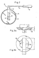
- the support roller shown in FIG. 2 for pressing the adhesive tape onto the edge surface of the ream to be examined with regard to the dust accumulation consists of a steel core 32, on the circumference of which a rubber jacket 34 is applied. Since this support roller should only exert a defined pressure on the adhesive tape, which corresponds to the weight of the roller, a special connection between the roller and the handle 36 is provided. This connection is designed in such a way that pins 38 are arranged on the axial end faces of the steel core 32, each of which, in a guided but movable manner, engages in an elongated hole 40 of a holding bracket 42, which holding bracket 42 is provided with a push rod 44 and a handle 46 attached to it. in the illustrated embodiment, the push rod 44 is welded at right angles to the center of the bracket 42.
- This constructive structure of the support roller prevents the drive force applied when moving the roller from having a component in the direction of the support surface of the support roller, so that a defined pressure always acts on the adhesive tape when the roller is moved.
- FIG. 3 of the drawings shows a section according to FIG. 3a and a plan view according to FIG. 3b for dust measurement by means of the so-called “Hunterlab” device.
- this diaphragm consists of a solid ring 46 with a height H.
- the ring is conically tapered on the inner circumference and on the outer circumference in the same sense, so that a large upper ring opening 48 and a lower, smaller ring opening 50 are provided in the interior of the ring 46 is.
- This lower, smaller ring opening 50 has a rectangular shape with a width b and a length 1, which is larger than the diameter D of the upper ring opening 48. The actual aperture opening is thus formed by the lower ring opening 50.
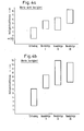
- FIG. 4a and 4b a diagram is shown in each case.
- the difference in brightness is plotted on the ordinate of the diagrams.
- the abscissa indicates whether it is the paper according to the invention or a commercial type I, II or III paper.
- the boxes indicated in the diagrams indicate the brightness difference areas for the respective paper quality, the reference size being the black surface of the reference base, with which there is practically a reflection of 0, ie a minimal reflectance brightness. If the dust removed from the edge of the paper giant is on the black reference surface due to the attached adhesive tape, the reflectance brightness varies depending on the amount of dust, ie the greater the more dust is present, the greater.
- the diagrams clearly show that the brightness difference values for the paper according to the invention are substantially lower than for the known paper types specified, ie the paper according to the invention has a substantially lower accumulation of dust in the region of the edges or edges which has arisen as a result of the cutting action on the paper.
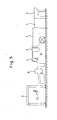
- Fig. 5 shows schematically a part of a system which shows, in succession, processing stations in which the paper web is acted on in different ways. In particular, various dedusting measures are taken.
- FIG. 5 shows, from left to right, a station A in which the paper web is guided past a break bar. This is followed by a station B, in which, if desired, the paper web is perforated through a rotary hole. This is followed by the longitudinal cutting of the paper web in a station C. The paper web is cross-cut in a subsequent station D, which is followed by a sorting switch E and a collecting station F, where the cut paper sheets are sorted or stacked. In the last station G, the stacked sheets of paper are transversely transported.
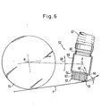
- the crushing bar consists of a hollow box 58, in which a suction nozzle 60 is fastened on the side facing away from the breaking edge 56, to which suction nozzle 60 a hose 62 is fastened.
- the breaking edge 56 is located on a block 64 which is fastened on the side of the hollow box 58 facing away from the suction nozzle 60.
- a suction channel 66 in block 64 which is aligned with a suction opening 68 in the hollow box 58.
- Two suction channels 66, 67 are provided in a symmetrical arrangement, so that the block 64 can be changed in position so that after the breaking edge 56 has been worn, the symmetrically arranged breaking edge 57 can be used.
- the entire crushing bar 52 can be pivoted back and forth about the central axis M of the roller 54 to a specific deflection angle ( ⁇ ).
- FIG. 7 shows station C in more detail.
- An upper knife 72 and a lower knife 74 are rotatably mounted in a frame 70 of this station, these knives being designed as circular knives which are arranged parallel to one another in the direction of their axis of rotation, a circular cutting edge 75 of the lower knife 74 and an annular cutting edge 73 of each Interacting upper knife 72 and overlap each other in a slitting area a.
- the axes of the circular knives 72, 74 are aligned parallel and one above the other perpendicular to the direction of movement of the paper web.
- the paper web runs continuously over the guide plate 76 and the suction table 78, with the aforementioned knife cutting the paper web lengthways. With this slitting, paper dust develops, which should be removed as completely as possible. In the large area of longitudinal cutting, this is done in three ways, namely by means of a first suction device 80 located immediately below the lower knife 74, and a subsequent one above the suction table 78 and behind the second suction device 82 located above the upper knife 72, and a third suction device 84 located below the suction table 78 in the direction of movement of the paper web behind the second suction device 82.
- first suction device 80 there are a row of suction openings 88 in an L-shaped lower knife bar 86 immediately below the lower knife 74, below which a suction box 9 is connected to the lower knife bar 86 and is connected to a hose 94 via a connecting piece 92.
- the guide plate 76 already mentioned is fastened to the vertical leg of the lower cutter bar 86 above a bar 96.
- a cover plate 98 is fastened in the inner angular region of the lower cutter bar 86 in order to prevent dust nests from forming there.
- an end plate 100 is attached, which extends to the lower cutter 74 and thus forms a suction space 102 in the lower region of the lower cutter together with the lower cutter 74, the strip 96, the guide plate 76 and the suction table 78.
- the second suction device 82 has a blow pipe 104, which is located below the suction table 78. In the radiation area of this blow pipe 104 there are slots 77 in the suction table 78, through which the interfaces of the paper web extend after the longitudinal cutting, so that dust still at the interfaces is blown off and directed into the mouth opening 106 of an upper suction pipe 108.
- the third suction device 84 is located behind the in relation to the direction of movement of the paper web.
- second suction device 82 and consists essentially of a suction box 110 located below the suction table 78, to which a hose 112 is attached.
- the suction box 110 is connected to elongated holes 114 in the suction table 78, through which the previously mentioned interfaces of the paper web run after the longitudinal cutting.
- this third suction device 84 there is a further guide plate 116, to which a pair of pulling rollers 118 is connected.
- FIG. 8b shows a section through an elongated hole 114 along the line b-b in FIG. 8a.
- the upper knife 72 and the lower knife 74 can be seen schematically on the left-hand side, and the suction table 78 adjoining them in the direction to the right, ie in the running direction of the paper web with the suction box 110 underneath.
- the suction table 78 adjoining them in the direction to the right, ie in the running direction of the paper web with the suction box 110 underneath.
- the suction table On the right side of the suction table is the already mentioned pair of pull rollers 118, which are pull rollers with which the paper web is pulled over the suction table.
- the edges 79 of the longitudinal slots 114 which extend transversely to the longitudinal direction of the longitudinal slots 114, are arched downward.
- the radius of this arching is about 3 mm when new and changes with increasing wear.
- the width of the longitudinal slots depends on the paper quality and is selected in exact coordination with the length of the longitudinal slots, the opening cross section of the longitudinal slots depending on the suction power and the available space in the machine.
- the slots are located immediately behind the slitter, but must be arranged in the area of uniform tension in front of the cross knife.
- a single, inherently rigid suction box or suction table does not necessarily have to be used.
- a corresponding design possibly with nested suction boxes, it is possible to change the position of the slots in the width direction in order to adapt to the respective sheet format.
- the convex edges 79 serve to fan out the interface of one or more superimposed paper webs if the paper web with the interface is continuously moved over the longitudinal slot 114 and air is sucked through the longitudinal slots into the suction box, which air is not only deforming Has an effect on the paper sheets in the longitudinal section area, but also has an effect in that residual dust still present, favored by the fanning out, is drawn off into the suction box.
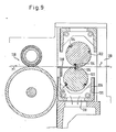
- FIG. 9 A corresponding suction device results from FIG. 9, where two identical knife drums 122 lying one above the other are rotatably mounted in a frame 120 in such a way that the knives 124 located therein come into contact with one another at a very specific point, so that at this point a cross cutting of the Paper web takes place.
- a U-shaped bar 125 which surrounds at least the lower half of the lower knife drum 122 and thus forms a suction space 126.
- suction openings 128 are formed, to which a suction device, not shown, is connected.
- a guide plate 130 for the paper web In the direction of movement of the paper web from left to right in front of the two knife drums 122 there is also a guide plate 130 for the paper web, which in the rest enlarges the suction space 126 up to the top of the lower knife drum.
- the running into the area of the cross cutters is stabilized by guiding the paper web over the suction table 78 already mentioned and described, so that a perfect cross cutting can take place.
- FIG. 10 The relevant suction device is shown in FIG. 10.
- a cross conveyor belt 132 is shown, on which the paper giant R rests.
- the paper giant R is laterally delimited by support bands 134 deflected about vertical axes, a small space remaining between the paper giant and the support bands.
- Underneath the conveyor belt 132 there is a suction box 136 with a suction nozzle 138 and a hose 140 adjoining it.
- suction openings 142 On the side of the suction box 136 there are suction openings 142 which are connected to the gap between paper rolls R and the support belts 134.
- the rejects obtained were re-sorted using a slotted basket.
- the acceptor of the sorter was first thickened to 14% solids by means of disk filtration, then diluted to 3.5% solids and then brought to a solids content of 28%. Thereafter, aftertreatment was carried out in the disperser at temperatures up to 95 ° C., if necessary using bleaching with peroxide or sodium dithionite (at approx. 6% and 50 to 60 ° C.).
- the pulp obtained was placed on a conventional paper machine. The papers produced for this were then cut as follows or subjected to the following conditions:
- Dust number for surface dust 2.2 to 2.5.
- the paper was colored yellow and had a brightness value of 80%
Landscapes
- Life Sciences & Earth Sciences (AREA)
- Forests & Forestry (AREA)
- Engineering & Computer Science (AREA)
- Mechanical Engineering (AREA)
- Paper (AREA)
- Details Of Cutting Devices (AREA)
- Duplication Or Marking (AREA)
- Inks, Pencil-Leads, Or Crayons (AREA)
- Filters For Electric Vacuum Cleaners (AREA)
Priority Applications (6)
| Application Number | Priority Date | Filing Date | Title |
|---|---|---|---|
| DE8484114648T DE3479749D1 (en) | 1984-12-03 | 1984-12-03 | Format paper with a low dust content, process for its manufacture and its use |
| AT84114648T ATE46378T1 (de) | 1984-12-03 | 1984-12-03 | Staubarmes formatpapier, verfahren zu dessen herstellung und verwendung desselben. |
| EP84114648A EP0183863B2 (fr) | 1984-12-03 | 1984-12-03 | Papier format pauvre en poussière, procédé pour sa fabrication et son emploi |
| JP60010700A JPS61132700A (ja) | 1984-12-03 | 1985-01-22 | 紙粉の少ない規格版紙およびその製法と応用 |
| DE3517402A DE3517402C2 (de) | 1984-12-03 | 1985-05-14 | Staubarmes Formatpapier, Verfahren zu dessen Herstellung und Verwendung desselben |
| JP4327828A JPH0693588A (ja) | 1984-12-03 | 1992-12-08 | 紙粉の少ない規格版紙 |
Applications Claiming Priority (1)
| Application Number | Priority Date | Filing Date | Title |
|---|---|---|---|
| EP84114648A EP0183863B2 (fr) | 1984-12-03 | 1984-12-03 | Papier format pauvre en poussière, procédé pour sa fabrication et son emploi |
Publications (3)
| Publication Number | Publication Date |
|---|---|
| EP0183863A1 true EP0183863A1 (fr) | 1986-06-11 |
| EP0183863B1 EP0183863B1 (fr) | 1989-09-13 |
| EP0183863B2 EP0183863B2 (fr) | 1991-10-23 |
Family
ID=8192328
Family Applications (1)
| Application Number | Title | Priority Date | Filing Date |
|---|---|---|---|
| EP84114648A Expired - Lifetime EP0183863B2 (fr) | 1984-12-03 | 1984-12-03 | Papier format pauvre en poussière, procédé pour sa fabrication et son emploi |
Country Status (4)
| Country | Link |
|---|---|
| EP (1) | EP0183863B2 (fr) |
| JP (2) | JPS61132700A (fr) |
| AT (1) | ATE46378T1 (fr) |
| DE (2) | DE3479749D1 (fr) |
Cited By (6)
| Publication number | Priority date | Publication date | Assignee | Title |
|---|---|---|---|---|
| DE4307241A1 (de) * | 1993-03-08 | 1994-09-15 | Steinbeis Temming Papier Gmbh | Holzhaltiges Aufzeichnungspapier für Tintenspritzaufzeichnungsverfahren |
| WO2002064333A1 (fr) * | 2001-02-14 | 2002-08-22 | Koenig & Bauer Aktiengesellschaft | Dispositif d'aspiration de copeaux pour dispositif de coupe longitudinale |
| WO2002066212A1 (fr) * | 2001-02-21 | 2002-08-29 | Koenig & Bauer Aktiengesellschaft | Dispositif de nettoyage pour dispositif de coupe longitudinale, et procede de nettoyage de ce dispositif de coupe longitudinale |
| WO2002090651A1 (fr) * | 2001-05-08 | 2002-11-14 | Alpha Calcit Füllstoff Gesellschaft Mbh | Procede de recyclage de dechets de pate |
| CN109397352A (zh) * | 2018-11-08 | 2019-03-01 | 长兴盛纺织有限公司 | 一种化纤丝切断用截断机 |
| IT201700117533A1 (it) * | 2017-10-18 | 2019-04-18 | Futura Spa | Impianto per la trasformazione di materiale cartaceo |
Families Citing this family (11)
| Publication number | Priority date | Publication date | Assignee | Title |
|---|---|---|---|---|
| JPH04240095A (ja) * | 1991-01-25 | 1992-08-27 | Takachiho Koeki Kk | 集塵システム |
| FI964403A0 (fi) * | 1996-11-01 | 1996-11-01 | Valmet Corp | Foerfarande foer avlaegsnande av dam i samband med arkskaermaskin i cellulosatorkmaskin eller motsvarande och arrangemang foer genomfoerande av foerfarandet |
| DE10132897A1 (de) * | 2000-07-25 | 2002-03-28 | Heidelberger Druckmasch Ag | Längsschneider mit Papierstaub-Absaugeinrichtung |
| JP4515612B2 (ja) * | 2000-09-12 | 2010-08-04 | リンテック株式会社 | 切断屑回収装置 |
| DE10130741A1 (de) * | 2001-06-19 | 2003-01-02 | Bielomatik Leuze & Co | Staubabsaugeinrichtung für Querschneider |
| JP2009002856A (ja) * | 2007-06-22 | 2009-01-08 | Ricoh Co Ltd | 紙粉測定方法及び紙粉測定装置 |
| DE102008024681A1 (de) * | 2008-05-21 | 2009-12-03 | WINKLER+DüNNEBIER AG | Maschinengestelltraverse zur Lagerung einer drehbaren Schneidwalze zum Schneiden von Flachmaterialstücken oder Materialbahnen |
| JP2012035360A (ja) * | 2010-08-06 | 2012-02-23 | Toyota Motor Corp | 切断装置 |
| JP5906547B2 (ja) * | 2014-07-23 | 2016-04-20 | デュプロ精工株式会社 | 古紙再生処理装置の断裁装置及び古紙再生処理装置の断裁方法 |
| CN105951523A (zh) * | 2016-06-27 | 2016-09-21 | 福建省晋江优兰发纸业有限公司 | 一种低克重拷贝纸的生产方法 |
| JP6952354B2 (ja) | 2016-09-14 | 2021-10-20 | 吉野石膏株式会社 | 切断装置、シート部材の製造装置、石膏系建材の製造装置 |
Citations (6)
| Publication number | Priority date | Publication date | Assignee | Title |
|---|---|---|---|---|
| DE217176C (fr) * | ||||
| GB291920A (en) * | 1927-04-08 | 1928-06-14 | Blackie & Son Ltd | Improvements in or relating to printing machinery |
| US2173167A (en) * | 1937-06-26 | 1939-09-19 | Oxford Paper Co | Paper and method of making the same |
| DE2006716A1 (de) * | 1969-02-14 | 1970-09-03 | Aktiebolaget Svenska Fläktfabriken, Nacka (Schweden) | Vorrichtung zum Absaugen von Staub von dünnschichtigem Material |
| DE2608239B2 (de) * | 1976-02-28 | 1978-11-16 | Feldmuehle Ag, 4000 Duesseldorf | Bildempfangsmaterial für elektrophotographische Verfahren und Verfahren zu seiner Herstellung |
| DE3219774A1 (de) * | 1982-05-26 | 1983-12-01 | Dr. Otto C. Strecker Kg, 6102 Pfungstadt | Staubabsaugeinrichtung fuer laengsschneider |
Family Cites Families (8)
| Publication number | Priority date | Publication date | Assignee | Title |
|---|---|---|---|---|
| US3135151A (en) * | 1961-03-06 | 1964-06-02 | Kimberly Clark Co | Paper slitter with dust removal vacuum device |
| US3272651A (en) * | 1961-10-30 | 1966-09-13 | Peninsular Paper Company | Paper cutting dust collector system and method |
| US3216298A (en) * | 1962-05-01 | 1965-11-09 | Warren S D Co | Paper finishing machine |
| DE1231106B (de) * | 1965-07-23 | 1966-12-22 | Jagenberg Werke Ag | Vorrichtung zum Laengsschneiden laufender Werkstoffbahnen |
| DE2164554A1 (de) * | 1971-12-24 | 1973-06-28 | Jagenberg Werke Ag | Vorrichtung zum staubfreien laengsschneiden laufender werkstoffbahnen aus papier, karton, kunststoffolie od. dgl |
| DE3148749C2 (de) * | 1981-12-09 | 1984-09-27 | Steinbeis Papier GmbH, 7121 Gemmrigheim | Papiere, vorzugsweise für den Bogendruck, hergestellt aus aufbereitetem Altpapier, und Verfahren zu deren Herstellung |
| DE3320526A1 (de) * | 1981-12-09 | 1984-12-13 | Steinbeis Papier GmbH, 7121 Gemmrigheim | Verfahren zur herstellung von papieren, papier und dessen verwendung |
| JPS59191068A (ja) * | 1983-04-14 | 1984-10-30 | Fuji Xerox Co Ltd | 転写用紙 |
-
1984
- 1984-12-03 DE DE8484114648T patent/DE3479749D1/de not_active Expired
- 1984-12-03 AT AT84114648T patent/ATE46378T1/de active
- 1984-12-03 EP EP84114648A patent/EP0183863B2/fr not_active Expired - Lifetime
-
1985
- 1985-01-22 JP JP60010700A patent/JPS61132700A/ja active Granted
- 1985-05-14 DE DE3517402A patent/DE3517402C2/de not_active Expired
-
1992
- 1992-12-08 JP JP4327828A patent/JPH0693588A/ja active Pending
Patent Citations (6)
| Publication number | Priority date | Publication date | Assignee | Title |
|---|---|---|---|---|
| DE217176C (fr) * | ||||
| GB291920A (en) * | 1927-04-08 | 1928-06-14 | Blackie & Son Ltd | Improvements in or relating to printing machinery |
| US2173167A (en) * | 1937-06-26 | 1939-09-19 | Oxford Paper Co | Paper and method of making the same |
| DE2006716A1 (de) * | 1969-02-14 | 1970-09-03 | Aktiebolaget Svenska Fläktfabriken, Nacka (Schweden) | Vorrichtung zum Absaugen von Staub von dünnschichtigem Material |
| DE2608239B2 (de) * | 1976-02-28 | 1978-11-16 | Feldmuehle Ag, 4000 Duesseldorf | Bildempfangsmaterial für elektrophotographische Verfahren und Verfahren zu seiner Herstellung |
| DE3219774A1 (de) * | 1982-05-26 | 1983-12-01 | Dr. Otto C. Strecker Kg, 6102 Pfungstadt | Staubabsaugeinrichtung fuer laengsschneider |
Non-Patent Citations (5)
| Title |
|---|
| ABSTRACT BULLETIN OF THE INSTITUTE OF PAPER CHEMISTRY, Band 49, Nr. 1, Juli 1978, Seite 46, Zusammenfassung 211, Appleton, Wisc., US; G.M. LAISHA et al.: "Effect of groundwood on properties of coating base paper", & TSELLYULOZA, BUMAGA, KARTON REF. INFORM. no. 25: 10-11 (Sept. 1977) * |
| H. HENTSCHEL: "Chemische Technologie de Zellstoff- und Papierherstellung", 3. Auflage, 1967, Veb Fachbuchverlag, Seiten 486-510, 682-697, Leipzig, DE * |
| PATENTS ABSTRACTS OF JAPAN, Band 6, Nr. 225 (P-154)[1103], 10. November 1982; & JP-A-57 128 346 (HONSHIYUU SEISHI K.K.) 09.08.1982 * |
| PATENTS ABSTRACTS OF JAPAN, Band 7, Nr. 121 (P-199)[1266], 25. Mai 1983; & JP-A-58 040 556 (RICOH K.K.) 09-03-1983 * |
| TAPPI JOURNAL, Band 67, Nr. 1, Januar 1984, Seiten 90-93, Atlanta, Georgia, US; U.B. MOHLIN et al.: "Some aspects of the interaction between mechanical and chemical pulps" * |
Cited By (13)
| Publication number | Priority date | Publication date | Assignee | Title |
|---|---|---|---|---|
| DE4307241A1 (de) * | 1993-03-08 | 1994-09-15 | Steinbeis Temming Papier Gmbh | Holzhaltiges Aufzeichnungspapier für Tintenspritzaufzeichnungsverfahren |
| WO2002064333A1 (fr) * | 2001-02-14 | 2002-08-22 | Koenig & Bauer Aktiengesellschaft | Dispositif d'aspiration de copeaux pour dispositif de coupe longitudinale |
| WO2002066212A1 (fr) * | 2001-02-21 | 2002-08-29 | Koenig & Bauer Aktiengesellschaft | Dispositif de nettoyage pour dispositif de coupe longitudinale, et procede de nettoyage de ce dispositif de coupe longitudinale |
| US7147724B2 (en) | 2001-02-21 | 2006-12-12 | Koenig & Bauer Aktiengesellschaft | Cleaning device for a longitudinal cutting device and method for cleaning the device |
| WO2002090651A1 (fr) * | 2001-05-08 | 2002-11-14 | Alpha Calcit Füllstoff Gesellschaft Mbh | Procede de recyclage de dechets de pate |
| AU2002235867B2 (en) * | 2001-05-08 | 2006-12-14 | Alpha Calcit Fullstoff Gesellschaft Mbh | Method for recycling pulp rejects |
| CN111093918A (zh) * | 2017-10-18 | 2020-05-01 | 未来股份公司 | 纸加工设备 |
| IT201700117533A1 (it) * | 2017-10-18 | 2019-04-18 | Futura Spa | Impianto per la trasformazione di materiale cartaceo |
| WO2019077639A1 (fr) * | 2017-10-18 | 2019-04-25 | Futura S.P.A. | Installation de conversion de papier |
| CN111093918B (zh) * | 2017-10-18 | 2021-07-02 | 未来股份公司 | 纸加工设备 |
| US11273572B2 (en) | 2017-10-18 | 2022-03-15 | Futura S.P.A. | Paper converting plant |
| CN109397352A (zh) * | 2018-11-08 | 2019-03-01 | 长兴盛纺织有限公司 | 一种化纤丝切断用截断机 |
| CN109397352B (zh) * | 2018-11-08 | 2021-03-30 | 江苏鸿顺合纤科技有限公司 | 一种化纤丝切断用截断机 |
Also Published As
| Publication number | Publication date |
|---|---|
| EP0183863B2 (fr) | 1991-10-23 |
| ATE46378T1 (de) | 1989-09-15 |
| DE3517402A1 (de) | 1986-06-19 |
| EP0183863B1 (fr) | 1989-09-13 |
| JPS61132700A (ja) | 1986-06-20 |
| DE3479749D1 (en) | 1989-10-19 |
| DE3517402C2 (de) | 1987-04-09 |
| JPH0693588A (ja) | 1994-04-05 |
| JPH0561399B2 (fr) | 1993-09-06 |
Similar Documents
| Publication | Publication Date | Title |
|---|---|---|
| EP0183863B1 (fr) | Papier format pauvre en poussière, procédé pour sa fabrication et son emploi | |
| DE1761233B1 (de) | Verfahren zum Rueckgewinnen von Fasern aus kunststoffbeschichtetem Altpapier und Vorrichtung zur Durchfuehrung des Verfahrens | |
| DE2331501A1 (de) | Verfahren und vorrichtung zur herstellung sehr starken packpapiers aus stroh | |
| DE69332719T2 (de) | De-inken von bedrucktem papier mittels eines agglomerierungsverfahrens | |
| DE10244521B3 (de) | Verfahren zur Aufbereitung von Altpapier | |
| EP0931872A1 (fr) | Procédé pour l'enlèvement d'impurités fines d'une suspension de fibres | |
| DE68916272T2 (de) | Verfahren zur Wiedergewinnung von Sekundärfasern. | |
| DE19526205C2 (de) | Verfahren und Anlage zur Herstellung einer mehrlagigen Papier- oder Kartonbahn | |
| DE68911462T2 (de) | Überführen einer feuchten Zellulosebahn. | |
| DE102008063785A1 (de) | Verfahren zur Aufbereitung von Altpapier enthaltenden Rohstoffen zu einer zur Erzeugung graphischer Papiere geeigneten Faserstoffsuspension | |
| EP1247892B1 (fr) | Traitement de vieux papiers contenant du bois | |
| DE69907442T2 (de) | Verfahren und vorrichtung zur behandlung von fasersuspensionen welche mineralien enthalten, wie gestrichenes altpapier, bei der papierherstellung | |
| DE10132743A1 (de) | Verfahren zur Aufteilung eines aus mehreren Papiersorten bestehenden Rohstoffes in mindestens zwei Papierfraktionen | |
| DE2550071A1 (de) | Verfahren und vorrichtung zum abtrennen einer faserbahn von einem sie tragenden band | |
| DE4341412C2 (de) | Verfahren zur Aufbereitung von flüllstoffhaltigem Altpapier | |
| DE10304393A1 (de) | Vorrichtung zum Abtrennen eines Randes von einer Faserstofflage | |
| DE19938976A1 (de) | Verfahren zur Aufbereitung eines holzstoffhaltigen Papierfaser-Rohstoffes | |
| EP1254986A1 (fr) | Procédé pour la fabrication d' une pâte à partir de matériaux contenant du papier | |
| DE29921008U1 (de) | Deinkingware | |
| EP0479141A1 (fr) | Procédé de préparation de matériaux fibreux et utilisation de ce procédé | |
| DE3320526A1 (de) | Verfahren zur herstellung von papieren, papier und dessen verwendung | |
| DE10033456A1 (de) | Verfahren sowie Vorrichtung zum Überführen einer flexiblen Materialbahn | |
| DE102008019197A1 (de) | Verfahren zur Entfernung von Störstoffen aus einer wässrigen Faserstoffsuspension | |
| DE19806732A1 (de) | Verfahren zur Entfernung von feinen Verunreinigungen aus einer Faserstoffsuspension | |
| DE102008013458A1 (de) | Verfahren zur Entfernung von Störstoffen aus einer wässrigen Faserstoffsuspension |
Legal Events
| Date | Code | Title | Description |
|---|---|---|---|
| PUAI | Public reference made under article 153(3) epc to a published international application that has entered the european phase |
Free format text: ORIGINAL CODE: 0009012 |
|
| AK | Designated contracting states |
Kind code of ref document: A1 Designated state(s): AT BE CH DE FR GB IT LI LU NL SE |
|
| 17P | Request for examination filed |
Effective date: 19860710 |
|
| 17Q | First examination report despatched |
Effective date: 19870601 |
|
| GRAA | (expected) grant |
Free format text: ORIGINAL CODE: 0009210 |
|
| AK | Designated contracting states |
Kind code of ref document: B1 Designated state(s): AT BE CH DE FR GB IT LI LU NL SE |
|
| REF | Corresponds to: |
Ref document number: 46378 Country of ref document: AT Date of ref document: 19890915 Kind code of ref document: T |
|
| ITF | It: translation for a ep patent filed | ||
| GBT | Gb: translation of ep patent filed (gb section 77(6)(a)/1977) | ||
| REF | Corresponds to: |
Ref document number: 3479749 Country of ref document: DE Date of ref document: 19891019 |
|
| ET | Fr: translation filed | ||
| NLS | Nl: assignments of ep-patents |
Owner name: STEINBEIS TEMMING PAPIER GMBH & CO. TE GLUECKSTADT |
|
| PLBI | Opposition filed |
Free format text: ORIGINAL CODE: 0009260 |
|
| REG | Reference to a national code |
Ref country code: CH Ref legal event code: PUE Owner name: STEINBEIS TEMMING PAPIER GMBH & CO. |
|
| ITPR | It: changes in ownership of a european patent |
Owner name: CESSIONE;STEINBEIS TEMMING PAPIER GMBH & CO. |
|
| REG | Reference to a national code |
Ref country code: GB Ref legal event code: 732 |
|
| 26 | Opposition filed |
Opponent name: JAGENBERG AG Effective date: 19900611 |
|
| NLR1 | Nl: opposition has been filed with the epo |
Opponent name: JAGENBERG AG . |
|
| REG | Reference to a national code |
Ref country code: FR Ref legal event code: TP |
|
| PUAH | Patent maintained in amended form |
Free format text: ORIGINAL CODE: 0009272 |
|
| STAA | Information on the status of an ep patent application or granted ep patent |
Free format text: STATUS: PATENT MAINTAINED AS AMENDED |
|
| RAP2 | Party data changed (patent owner data changed or rights of a patent transferred) |
Owner name: STEINBEIS TEMMING PAPIER GMBH & CO. |
|
| 27A | Patent maintained in amended form |
Effective date: 19911023 |
|
| AK | Designated contracting states |
Kind code of ref document: B2 Designated state(s): AT BE CH DE FR GB IT LI LU NL SE |
|
| REG | Reference to a national code |
Ref country code: CH Ref legal event code: AEN |
|
| ITF | It: translation for a ep patent filed | ||
| ET3 | Fr: translation filed ** decision concerning opposition | ||
| NLR2 | Nl: decision of opposition | ||
| ITTA | It: last paid annual fee | ||
| GBTA | Gb: translation of amended ep patent filed (gb section 77(6)(b)/1977) | ||
| NLR3 | Nl: receipt of modified translations in the netherlands language after an opposition procedure | ||
| K2C2 | Correction of patent specification (partial reprint) published |
Effective date: 19890913 |
|
| PGFP | Annual fee paid to national office [announced via postgrant information from national office to epo] |
Ref country code: GB Payment date: 19931203 Year of fee payment: 10 |
|
| PGFP | Annual fee paid to national office [announced via postgrant information from national office to epo] |
Ref country code: LU Payment date: 19931216 Year of fee payment: 10 |
|
| PGFP | Annual fee paid to national office [announced via postgrant information from national office to epo] |
Ref country code: SE Payment date: 19931228 Year of fee payment: 10 Ref country code: DE Payment date: 19931228 Year of fee payment: 10 |
|
| PGFP | Annual fee paid to national office [announced via postgrant information from national office to epo] |
Ref country code: FR Payment date: 19931230 Year of fee payment: 10 Ref country code: AT Payment date: 19931230 Year of fee payment: 10 |
|
| PGFP | Annual fee paid to national office [announced via postgrant information from national office to epo] |
Ref country code: NL Payment date: 19931231 Year of fee payment: 10 |
|
| PGFP | Annual fee paid to national office [announced via postgrant information from national office to epo] |
Ref country code: CH Payment date: 19940104 Year of fee payment: 10 |
|
| PGFP | Annual fee paid to national office [announced via postgrant information from national office to epo] |
Ref country code: BE Payment date: 19940112 Year of fee payment: 10 |
|
| EPTA | Lu: last paid annual fee | ||
| PG25 | Lapsed in a contracting state [announced via postgrant information from national office to epo] |
Ref country code: LU Free format text: LAPSE BECAUSE OF NON-PAYMENT OF DUE FEES Effective date: 19941203 Ref country code: GB Effective date: 19941203 Ref country code: AT Effective date: 19941203 |
|
| PG25 | Lapsed in a contracting state [announced via postgrant information from national office to epo] |
Ref country code: SE Effective date: 19941204 |
|
| PG25 | Lapsed in a contracting state [announced via postgrant information from national office to epo] |
Ref country code: LI Effective date: 19941231 Ref country code: CH Effective date: 19941231 Ref country code: BE Effective date: 19941231 |
|
| EAL | Se: european patent in force in sweden |
Ref document number: 84114648.3 |
|
| BERE | Be: lapsed |
Owner name: STEINBEIS TEMMING PAPIER G.M.B.H. & CO. Effective date: 19941231 |
|
| PG25 | Lapsed in a contracting state [announced via postgrant information from national office to epo] |
Ref country code: NL Effective date: 19950701 |
|
| GBPC | Gb: european patent ceased through non-payment of renewal fee |
Effective date: 19941203 |
|
| PG25 | Lapsed in a contracting state [announced via postgrant information from national office to epo] |
Ref country code: FR Effective date: 19950831 |
|
| REG | Reference to a national code |
Ref country code: CH Ref legal event code: PL |
|
| NLV4 | Nl: lapsed or anulled due to non-payment of the annual fee |
Effective date: 19950701 |
|
| EUG | Se: european patent has lapsed |
Ref document number: 84114648.3 |
|
| PG25 | Lapsed in a contracting state [announced via postgrant information from national office to epo] |
Ref country code: DE Effective date: 19951003 |
|
| REG | Reference to a national code |
Ref country code: FR Ref legal event code: ST |