EP0184034A2 - Milieu d'enregistrement magnétique perpendiculaire et sa méthode de fabrication - Google Patents
Milieu d'enregistrement magnétique perpendiculaire et sa méthode de fabrication Download PDFInfo
- Publication number
- EP0184034A2 EP0184034A2 EP85114367A EP85114367A EP0184034A2 EP 0184034 A2 EP0184034 A2 EP 0184034A2 EP 85114367 A EP85114367 A EP 85114367A EP 85114367 A EP85114367 A EP 85114367A EP 0184034 A2 EP0184034 A2 EP 0184034A2
- Authority
- EP
- European Patent Office
- Prior art keywords
- recording medium
- perpendicular magnetic
- atomic percent
- balance
- thin film
- Prior art date
- Legal status (The legal status is an assumption and is not a legal conclusion. Google has not performed a legal analysis and makes no representation as to the accuracy of the status listed.)
- Granted
Links
Images










Classifications
-
- G—PHYSICS
- G11—INFORMATION STORAGE
- G11B—INFORMATION STORAGE BASED ON RELATIVE MOVEMENT BETWEEN RECORD CARRIER AND TRANSDUCER
- G11B5/00—Recording by magnetisation or demagnetisation of a record carrier; Reproducing by magnetic means; Record carriers therefor
- G11B5/62—Record carriers characterised by the selection of the material
- G11B5/64—Record carriers characterised by the selection of the material comprising only the magnetic material without bonding agent
- G11B5/65—Record carriers characterised by the selection of the material comprising only the magnetic material without bonding agent characterised by its composition
- G11B5/657—Record carriers characterised by the selection of the material comprising only the magnetic material without bonding agent characterised by its composition containing inorganic, non-oxide compound of Si, N, P, B, H or C, e.g. in metal alloy or compound
-
- Y—GENERAL TAGGING OF NEW TECHNOLOGICAL DEVELOPMENTS; GENERAL TAGGING OF CROSS-SECTIONAL TECHNOLOGIES SPANNING OVER SEVERAL SECTIONS OF THE IPC; TECHNICAL SUBJECTS COVERED BY FORMER USPC CROSS-REFERENCE ART COLLECTIONS [XRACs] AND DIGESTS
- Y10—TECHNICAL SUBJECTS COVERED BY FORMER USPC
- Y10S—TECHNICAL SUBJECTS COVERED BY FORMER USPC CROSS-REFERENCE ART COLLECTIONS [XRACs] AND DIGESTS
- Y10S428/00—Stock material or miscellaneous articles
- Y10S428/90—Magnetic feature
-
- Y—GENERAL TAGGING OF NEW TECHNOLOGICAL DEVELOPMENTS; GENERAL TAGGING OF CROSS-SECTIONAL TECHNOLOGIES SPANNING OVER SEVERAL SECTIONS OF THE IPC; TECHNICAL SUBJECTS COVERED BY FORMER USPC CROSS-REFERENCE ART COLLECTIONS [XRACs] AND DIGESTS
- Y10—TECHNICAL SUBJECTS COVERED BY FORMER USPC
- Y10S—TECHNICAL SUBJECTS COVERED BY FORMER USPC CROSS-REFERENCE ART COLLECTIONS [XRACs] AND DIGESTS
- Y10S428/00—Stock material or miscellaneous articles
- Y10S428/922—Static electricity metal bleed-off metallic stock
- Y10S428/9265—Special properties
- Y10S428/928—Magnetic property
-
- Y—GENERAL TAGGING OF NEW TECHNOLOGICAL DEVELOPMENTS; GENERAL TAGGING OF CROSS-SECTIONAL TECHNOLOGIES SPANNING OVER SEVERAL SECTIONS OF THE IPC; TECHNICAL SUBJECTS COVERED BY FORMER USPC CROSS-REFERENCE ART COLLECTIONS [XRACs] AND DIGESTS
- Y10—TECHNICAL SUBJECTS COVERED BY FORMER USPC
- Y10T—TECHNICAL SUBJECTS COVERED BY FORMER US CLASSIFICATION
- Y10T428/00—Stock material or miscellaneous articles
- Y10T428/26—Web or sheet containing structurally defined element or component, the element or component having a specified physical dimension
-
- Y—GENERAL TAGGING OF NEW TECHNOLOGICAL DEVELOPMENTS; GENERAL TAGGING OF CROSS-SECTIONAL TECHNOLOGIES SPANNING OVER SEVERAL SECTIONS OF THE IPC; TECHNICAL SUBJECTS COVERED BY FORMER USPC CROSS-REFERENCE ART COLLECTIONS [XRACs] AND DIGESTS
- Y10—TECHNICAL SUBJECTS COVERED BY FORMER USPC
- Y10T—TECHNICAL SUBJECTS COVERED BY FORMER US CLASSIFICATION
- Y10T428/00—Stock material or miscellaneous articles
- Y10T428/26—Web or sheet containing structurally defined element or component, the element or component having a specified physical dimension
- Y10T428/263—Coating layer not in excess of 5 mils thick or equivalent
- Y10T428/264—Up to 3 mils
- Y10T428/265—1 mil or less
Definitions
- the present invention relates generally to a perpendicular magnetic recording medium and, particularly, a magneto-optic recording medium, and a method of producing the same.
- rare earth denotes “rare earth element”
- recording medium herein is used in a broadest sense.
- a great number of microscopic magnetic domains are magnetized minutely and separately below the Curie temperature when no laser beam is incident thereupon, but demagnetized above the Curie temperature when the laser beam is incident thereupon, because of a rise in temperature on the thin film.
- polycrystalline metal thin films such as MnBi, MnCuBi, CoCr, etc.
- the present invention relates, in particular, to rare earth - transition metal amorphous metal ,thin films.
- the amorphous metal thin films are suitable for a magneto-optic recording material, because in contrast to pollycrystalline thin films there exist no crystal grain boundaries which will cause noise, and additionally there exists an advantage such that a wide thin film can readily be produced.
- the rare earth - transition metal amorphous metal alloy film As a magneto-optic recording medium of a high memory density, it is required that the easy axis for magnetization thereof is perpendicular to the film plane. This necessary condition, the perpendicular magnetic anisotropy is not always induced at any cases in the above amorphous metal alloys, but the easy axis for magnetization shows rather a tendency to be arranged in the direction parallel to the film plane depending upon an effect produced by an occurrence of a demagnetizing field. Therefore, in order to obtain a perpendicular magnetic film, it is necessary to provide a uniaxial anisotropic magnetic energy enough to overcome the above demagnetizing field.
- perpendicular magnetic anisotropy embraces at least ones that satisfy above conditions.
- the saturation magnetization Ms is great enough to stably maintain microscopic magnetic domains and additionally that the uniaxial magnetic anisotropy constant Ku is sufficiently large.
- a laser beam is usually used as the writing power source, it is required that the Curie temperature Tc is sufficiently low, e.g., approximately ranging from 100 to 200°C; the crystallization temperature Tcry is sufficiently higher than the Curie temperature Tc; and the difference in temperature between both is at least about 50°C, and preferably, about 100°C or more.
- the most well-known combination of rare earth elements and transition metals as the perpendicular magnetic anisotropic metal alloy thin film is that of heavy rare earth elements and iron.
- the typical examples are Tb-Fe, Gd-Fe, Dy-Fe, Gd-Tb-Fe, Tb-Dy-Fe, etc.
- Tb-Fe for instance, the magnetic characteristics are such that the Curie temperature Tc is 140 to 250°C; the Kerr rotation angle Ok is approximately 0.3 degrees; the saturation magnetization Ms is 50 to 100 emu/cc, and the uniaxial perpendicular magnetic anisotropy constant Ku is 0.1 to 1 x 10 6 erg/cc.
- a further object is to provide methods for producing such a perpendicular magnetic recording medium.
- the invention provides rare earth - transition metal amorphous alloy thin films provided with perpendicular magnetic anisotropy, which are useful in magnetically (or further megneto-optically) recording data in a high memory density.
- the invention also provides a perpendicular magnetic recording medium (and, particularly, magneto-optic recording medium) having excellent stable perpendicular magnetic recording properties, preferably while reducing the material cost and eliminating complicated fabricating processes so as to well be applicable to a large scale mass production process.
- the present invention provides a perpendicular magnetic recording medium(and particularly, magneto-optic recording medium) having a composition with the key elements of iron and rare earth element(s), or additionally Co thereto, the rare earth element(s) being mainly of neodymium Nd and/or praseodymium Pr.
- the perpendicular magnetic recording medium consists essentially of 21 to 60 (preferably 31 to 60) atomic percent rare earth elements R and the balance of iron Fe wherein 70-100 atomic percent of the R being neodymium Nd and/or praseodymium Pr the balance of the R being one or more selected from the group consisting of yttrium Y, lanthanum La, cerium Ce, samarium Sm, gadolinium Gd, terbium Tb, dysprosium Dy, holmium Ho, erbium Er and ytterbium Yb.
- the symbol "R" refers to the rare earth elements hereinabove specified, however, the rare earth elements R may not be pure elements and may contain other rare earth elements other than those specified above in small amounts.
- the perpendicular magnetic recording medium having the composition of the first aspect wherein cobalt Co of less than 50 (preferably less than 30) atomic percent of the entire Fe is substituted for Fe.
- the perpendicular magnetic recording medium additionally comprises not exceeding 10 atomic percent of at least one additional element M selected from the group consisting of nickel Ni, zirconium Zr, niobium Nb, vanadium V, tantalum Ta, chromium Cr, molybdenum Mo, tungsten W, manganese Mn, bismuth Bi, aluminium Al, solicon Si, lead Pb , germanium Ge, tin Sn, antimony Sb and hafnium Hf.
- additional element M selected from the group consisting of nickel Ni, zirconium Zr, niobium Nb, vanadium V, tantalum Ta, chromium Cr, molybdenum Mo, tungsten W, manganese Mn, bismuth Bi, aluminium Al, solicon Si, lead Pb , germanium Ge, tin Sn, antimony Sb and hafnium Hf.
- the composition can be expressed by a formula: R(Fe,Co)M, which includes 21 to 60 atomic percent rare earth elements R,0 to 10 atomic percent additional element(s) M and the balance of Fe and C o, wherein Co amounts to less than 50 atomic percent of the sum of Fe and Co to be counted as the balance and wherein 70-100 atomic percent of the entire R consists of Nd and/or Pr(Nd, Pr), the balance of R being one or more of Y, La, Ce, Sm, Gd, Tb, Dy, H o, Er and Yb; and wherein, here, Ti is counted as M in the case where Co is present.
- R(Fe,Co)M which includes 21 to 60 atomic percent rare earth elements R,0 to 10 atomic percent additional element(s) M and the balance of Fe and C o, wherein Co amounts to less than 50 atomic percent of the sum of Fe and Co to be counted as the balance and wherein 70-100 atomic percent of the entire R consists of N
- the method of fabricating the perpendicular magnetic recording medium according to the present invention comprises, in a process for producing a thin film on a substrate by a metal gas deposition technique, the steps of:
- the Kerr rotation angle 9k is significantly increased by oxidization in the film surface or by SiO coating on the film surface, while a combination thereof is useful, too.
- the perpendicular magnetic or magneto-optic recording medium it is possible to obtain an amorphous metal alloy thin film of perpendicular magnetic anisotropy provided with characteristics such that the Curie temperature Tc is from 70 to 250°C; the saturation magnetization Ms is about 450 emu/cc or more; the uniaxial perpendicular magnetic anisotropy constant Ku is at least 1 x 10 6 erg/cc and up to 2.5 to 7 x 10 6 erg/cc or more, the Kerr rotation angle ek is about 0.3 - 0.55 degree or more; that is, which are each equivalent or superior to those of heavy rare earth - iron amorphous thin films, in spite of the fact that iron and light rare earth elements such as Nd and/or Pr are used which are relatively abundant in resources and less expensive.
- the Curie temperature Tc is from 70 to 250°C
- the saturation magnetization Ms is about 450 emu/cc or more
- the perpendicular magnetic anisotropy constant Ku of at least 1 x 10 6 erg/cc provides a perpendicular magnetic recording medium which can be written or read at least through a magnetic head. With the high Kerr rotation angle the perpendicular magnetic thin film can be written or read magneto-optically.
- the Curie temperature Tc and the Kerr rotation angle ek can be increased up to 0.5 degree or more by substituting Co for a part of Fe.
- a stillmore significant improvement in the increase in the Kerr rotation angle ek can be obtained by oxidizing the film surface or coating by SiC, or a combination thereof based on the thin film hereinabove mentioned.
- the large Kerr rotation angle provides a higher S/N ratio.
- the composition of the medium of the present invention can be generally expressed by a formula R 21-60 (Fe 1-y Co y )balM 0-10 , wherein y is less than 0.5 by atomic ratio and 70-100 at % of R consists of Nd and/or Pr. That is to say, 21 to 60 atomic percent rare earth elements R are included in the whole composition; however, 70 atomic percent or more of the entire R is Nd and/or Pr. It is particularly preferred to use Nd. Further, it is also possible to use one or more of other rare earth elements such as Ce, Y, S m, Dy, Tb, Hot Gd, La, Er and Yb as the balance of R from the standpoint of easiness in procurement. It is preferred that the balance (Fe 1-y Co y ) is at least 40 atomic percent.
- the temperature difference of more than 50°C between Tcry and Tc and a Ku of at least 1 x 10 6 erg/cc are obtained, which is generally useful as a perpendicular magnetic recording medium which can be recorded through a magnetic head.
- the content of R should be between 21 and 60 atomic percent (preferably 31 % or more). More preferred is an R range from 33 to 50 % providing Ku of 3 x 10 6 erg/cc or more with a desired stability of film, and most preferred is an R range from 35 to 45 % in view of Ku.
- the dependence of the perpendicular magnetic anisotropy constant Ku upon the content x of rare earth element R is clearly shown in Fig. 8.
- the balance of the R consists primarily of Fe. However, it is also possible that Co is substituted for less than 50 (preferably less than 30) atomic percent of the entire Fe to be counted as the balance where Co is not contained in order to increase the saturation magnetization Ms, the Curie temperature Tc and the Kerr rotation angle, and further to improve the corrosion resistance of the thin film, without deteriorating the characteristics required for generally perpendicular magnetic or particularly magneto-optic thin films. If Co is substituted for Fe in an amount less than 50 % of Fe, the temperature difference between the crystallization temperature Tcry and the Curie temperature Tc becomes small and Kerr rotation angle ⁇ k becomes small, too. Besides, if so, targets for sputtering become brittle resulting in difficulty in production thereof.
- Co substitution should be less than 50 at % of the entire Fe. So long as the Kerr rotation angle is concerned, a Co substitution amount for Fe from about 8 at % to less than 30 at % is preferred ( ⁇ k of 0.45° or more ), and a Co substitution amount of about 12 to about 27 at % is most preferred (ek of 0.5° or more).
- additional metal elements such as Ni, Zr, Nb, V, Ta, Cr, Mo, W, Mn, Bi, Al, Pb, Sb, Ge, Sn and Ef
- additional elements M which further embraces Si
- the sum of M does not exceed 10 at %.
- the Ku can be as high as 3 x 10 6 erg/cc, provided that the specific process of the present invention is applied.
- a protective layer of SiO 2 or A lN is provided to improve the corrosion resistance of the thin film.
- the incorporation of Co and/or some of the additional elements M in the Fe(Nd, Pr) alloy system improves the corrosion resistance of the thin film per se, such M being one or more of Ni, Zr, Nb, V, Ta, Cr, Mo, W, Al, Hf, Ti, Ni and Si.
- the Curie temperature Tc should be low and the crystallization temperature Tcry should be high, and the difference between the two should be great.
- Fig. 2 shows the dependence of the Curie temperature Tc, the crystallization temperature Tcry and the saturation magnetization Ms in Fe 100-x Nd x upon the R(Nd) content x.
- F ig. 2 indicates that the change rate in both Tc or Ms is small over a wide range and therefore it is possible to fabricate very stable prooucts in quality with more easiness as compared with heavy rare earth - iron perpendicular magnetic anisotropy thin films.
- the temperature difference (Tcry-Tc) is at least 50°C.
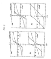
- the solid and broken lines correspond to curves obtained at a perpendicular direction ( ⁇ ) and parallel direction (//) of the film plane by applying an external magnetic field perpendicular and parallel to the film plane, respectively.
- These curves indicate that the samples are perpendicularly magnetizable at both the temperatures but the residual magnetism is very small at 27°C but increases at a lower temperature -l96°C.
- the Kerr rotation angle Ok of these films are 0.3 degree, which is roughly equal to or more than that of the heavy rare earth - iron amorphous perpendicular magnetic film.
- the saturation magnetization Ms is fairly high, it is necessary for the perpendicular magnetic recording medium that the perpendicular magnetic anisotropy constant Ku is greater than 1 x 10 6 erg/cc, and Ku of at least 2.5 x 10 6 erg/cc is preferred.
- substrate materials for the amorphous thin film glass, A 1. polyimido resin, polyester resin, etc. are generally usable.
- the substrate should be maintained at a temperature between 180°C and a temperature lower than the crystallization temperature in order to obtain a perpendicular magnetic anisotropy film, it is necessary to use a substrate material which can withstand the above temperature.
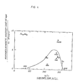
- Fig. 4 shows the dependence of the perpendicular magnetic anisotropy constant Ku upon the substrate temperature in Fe 65 Nd 35 .
- This curve clearly indicates that the anisotropy constant Ku is near its maximum between 260 and 290°C.
- the black circles represent that the samples are perpendicularly anisotropic
- the white circles represent that the samples are not perpendicularly anisotropic (but in-plane anisotropic)
- the numerals near the circles designate the thickness (A) of the sample films.
- this curve indicates that if the substrate temperature Ts exceeds the crystallization temperature Tcry (about 320°C), the perpendicular magnetic anisotropic characteristics are not present (Ku is almost zero).
- amorphous phase or microfine-crystalline phase of about a few tenths of a nm to about 10 nm in the average is desirable; that is, it is desirable that there exist no crystal grain boundaries which will cause noise as already explained.
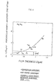
- Fig. 6 shows the dependence of the anisotropy constant Ku upon film thickness D, which indicates that the perpendicular magnetic anisotropy constant Ku larger than 2 M s 2 can be obtained at a thickness D of 0.3 ⁇ m or more, and Ku > 2.5 x 10 6 erg/cc can be obtained when the thickness D exceeds about 0.7 ⁇ m.
- the black circles represent that the film is of perpendicular anisotropy while the white circles represent that the film is not of perpendicular anisotropy.
- the numerals near circles designate substrate temperature Ts(°C).
- the thin film according to the present invention can be formed in accordance with a metal gas deposition (or so-called vapor deposition) technique; that is, by any of vacuum deposition method, PVD such as sputtering, ion plating, etc., CVD or the like.
- a metal gas deposition or so-called vapor deposition
- the samples are fabricated within an argon Ar atmosphere under pressure of about 2.67 ⁇ 10 -1 mbar (26.7 P a) (2 x 10 -1 Torr).
- Fig. 7 shows the dependence of the anisotropy constant Ku upon Ar pressure. Similarly, the black circles represent that the samples are perpendicular anisotropy while the white circles represent that the samples are not perpendicular anisotropy; the numerals near the circles represent film thickness ( ⁇ ). Fig. 7 indicates that the change in Ar pressure P has a relatively less influence upon the Ku than other factors such as the substrate temperature or the film thickness D.
- a magnetic field of a few to several tens Oe to the substrate in the direction perpendicular thereto.
- This magnetic field can readily be obtained by passing a direct current to a solenoid of a sheath wire for heating wound in a coil and disposed under the film substrate.
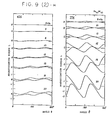
- Fig. 9 (2) is an example of the torque curves measured in various fields at 4, 2, 77 and 300K.
- e is the angle between the field direction and a direction in the film plane
- m) to show in more detail the change in torque curves with temperature. It is seen that both the torque amplitude and the rotational hysteresis loss W increase with decreasing temperature down to about 84K, and then decrease. It should also be noted here that the slope at ⁇ 0 changes its sign from positive to negative with decreasing temperature from about 80 to 4.2k.
- the thin film according to the present invention is provided with relatively large saturation magnetization Ms, when used as a magneto-optic disk for thermo-magnetic writing of data, it is possible to reduce the magnitude of magnetic field to be applied from the outside, because the leak magnetic flux coming from the surroundings can effectively be utilized.
- Fig. 10 shows the perpendicular magnetic anisotropy constant Ku and the hysteresis loss W at low temperatures.
- the Ku increases with decreasing temperature and reaches its maximum 3 x 10 7 erg/cc near liquid nitrogen temperature of 80K (-193°C).
- the hysteresis loss W reaches its maximum at 100K (-173°C) or less.
- Fig. 11 shows temperature characteristics of the thin film including Co, in particular.
- This graphical representation indicates that the addition of Co increases the Curie temperature Tc and the temperature T I at which the perpendicular magnetic anisotropy constant Ku attains a maximum value (i.e., it is believed to be a transition temperature at which the magnetic anisotropy transforms from unidirectional characteristic perpendicular to film plane to cone characteristic) , without increasing the crystallization temperature Tcry.
- test samples were all fabricated on glass substrates within an Ar atmosphere in accordance with a rf sputtering method.
- the pressure within the sputter vessel is evacuated down to 5 x 10 -7 Torr (3.7 x 10 -9 Pa) or less.
- the sputtering speed was approximately 2pm/h.
- No bias voltage was applied to the sample substrate during the sputtering process.
- the substrates were heated by adjusting the magnitude of current passed through a heater coil disposed under the substrate.
- the heater coil comprised cylindrical copper bobbin the outer circumference of which was wound by a sheath wire. Since a direct current was applied through the heater coil, a magnetic field of a few to several tens Oe was applied to the substrate.
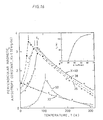
- Fig. 1 The dependence of the magnetization M is upon temperature T shown in Fig. 1 with different values of Nd content x.
- the dependence of the Curie temperature Tc, the crystallization temperature Tcry and the saturation magnetization Ms upon the Nd content x is shown in Fig. 2, respectively.
- Fig. 2 is based on Example 1, as discussed previously.
- F ig. 2 also shows that Ns at 77 K and 30CK depends upon the composition Fe-Nd.
- Tcry-Tc the temperature difference (Tcry-Tc) amounts to at least about 50°C, while at 30 at % or more the difference amounts to 200°C or more.
- the magnetization M was measured within a magnetic field of 10 kOe (8 x 10 5 A/m) after the samples have been magnetized to the saturation point in the direction of easy axis of magnetization.
- a vibrating sample type magnetometer was used to measure the magnetization M.
- the Curie temperatures Tc were obtained from points of intersection between the extrapolation curve M 2 /T (where M is the magnetization and T is the temperature) and the horizontal temperature axis.
- M the magnetization and T is the temperature
- the temperature was increased gradually as shown by the solid lines in Fig. 1.
- the dashed lines show the magnetization curves obtained when the temperature was lowered from a high temperature more than 1000K (727°C).
- the magnetic characteristics of the sputtered film were measured at 77K (-196°C) and 300K (27°C) in a directions perpendicular ( ⁇ ) and parallel (//) to the film plane, and are shown in Fig. 3, which shows parpendicular anisotropy as discussed previously.
- the Kerr rotation angle 6k was measured on this film to be 0.3 uegree which is substantially equivalent to that of the heavy rare earth - iron perpendicular magnetic film.
- Fig. 6 The dependence of the anisotropy constant Ku upon film thickness D is shown in Fig. 6, wherein black circles represent perpendicular anisotropy and white circles represent in-plane anisotropy. This figure indicates that a thickness D of 0.3 ⁇ m or more is necessary to obtain Ku larger than 2 ⁇ Ms 2 , and D of 0.7pm or more is necessary for Ku of at least 2.5 x 10 6 erg/cc.
- T s was 210 to 290°C
- D was 6140 to 12650A (0.6 to 1.2 ⁇ m)
- Ar pressure was varied.
- Fig. 7 The dependence of the anisotropy constant Ku upon Ar pressure is shown in Fig. 7. This figure indicates that the Ar pressure exerts a less influence upon Ku than other factors such as Ts or D.
- the dependence of the anisotropy constant Ku upon Nd content x is shown in Fig. 8.
- the Ku reaches its maximum value of 1 to 2 x 10 7 crg/cc near Nd 40 .
- Ku rapidly decreases thus Ku drops down below 2.5 x 1C 6 erg/cc at a Nd amount of less than 31 at %.
- This curve indicates that when the R content lies between 33 and 55 atomic percent, the Eu is within a preferable range of 3 x 10 6 erg/cc or more.
- each plotted value is an average of several test samples fabricated at different times. At 21 at % Nd, the film shows perpendicular magnetic anisotropy.
- Various Fe 60 Nd 35 M 5 thin films (where M is at least one of Ni, Zr, Nb, V, Ta, Cr, Mo, W, Mn, Bi, Al, Si, Pb, Sb, Ge and Sn) are formed under the following condition: Ar pressure is 1 to 2 x 10 -1 Torr (13.3 x 26.6 Pa); Ts is 220 to 290°C; and D is 6300 to 11000A (0.6 to 1.1 ⁇ m). It is possible to obtain perpendicular magnetic anisotropy for each test sample.
- An Fe 40 Co 25 Nd 35 thin film was formed under the following conditions: Ar pressure was 2 x 10 -1 Torr (26.6 Pa); T s was 240°C; and D was 7400A (0.74 ⁇ m).
- the anisotropy constant Ku was 2.5 x 10 6 erg/cc or more.
- An Fe 60 Nd 25 Pr 15 thin film was formed under the following conditions: An pressure was 1.5 to 2 x 10 -1 Torr (19.5 to 26.6 Pa); Ts was 260°C; and D was 7900A (0.79 ⁇ m).
- the anisotropy constant Ku was 2.5 x 10 6 erg/cc or more.
- Three thin films of Fe 60 Nd 32 Dy 8 ' Fe 58 Nd 32 Ce 10 and Fe 57 Nd 30 Co 10 V 3 were formed under the following conditions: Ar pressure was 1 to 2 x 10 -1 Torr (13.3 to 26.6 Pa); T s was 240 to 290°C; and D was 7300 to 11000 A (0.73 to 1.1 ⁇ m).
- the anisotropy constants Ku thereof were each 2.5 x 10 6 erg/cc or more.
- Two Fe 65 Nd 35 and Fe 60 Nd 40 thin films were formed under the following conditions: Ar pressure was 2 x 10 -1 Torr (26.6 Pa); Ts was 290°C and 250°C, respectively; and D was 12650A (1.26 ⁇ m) and 4860A (0.48 ⁇ m), respectively.
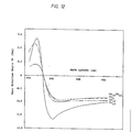
- rapidly increases above 340 nm and reaches a roughly constantn high level at ⁇ above 500 nm.
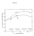
- F ig. 13 shows the change of the Kerr rotation angle
- as a function of the Co concentration y. for (Fe 1-y Co y ) 60 Nd 40 at ⁇ 500 and 633 nm to illustrate its dependence upon the composition.
- increases as the Co concentration y increases, depicting a peak around y 0.25.
- the surface oxidization treatment was effected by maintaining the film on the substrate at a temperature of 100-150°C within the sputter vessel for a half to one hour after sputtering.
- the surface oxidization is more convenient in preparation than the coating treatment such as SiO - coating or the like applied onto (above) the film surface, since in the oxidization treatment the film surface in situ can be subjected to oxidization.
- the present invention provides a great advantage in this respect over the prior art. Further, such oxidized layer can serve as a protective layer of the base thin film.
- the SiO coating can increase the Kerr rotation angle, too. This means the conventional or additional treatment or layer provision can further increase the Kerr rotation angle ⁇ k, which is also counted as an advantage of the present invention.
- SiO coating or any other coating may be applied on the oxidized layer hereinabove mentioned too.
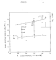
- the peak temperature T 1 for Ku shifts as a function of the composition (e.g., Nd concentration x at %), which is also shown in Fig. 16, at the upper right corner.
- a 150A (15nm) thick Fe 60 Nd 40 film was made on a cleaved rocksalt substrate at Ts of 220°C, and a high resolution transmission electron micrograph thereof is shown on Fig. 17. There is clearly observed a lattice image of a 0.2 nm spacing. The average size of such a region (clusters) varies from place to place (2-10nm), however, on the average of about 3-5 nm. This feature was also found in most of the films examined in the present invention.
- Each sample shows the perpendicular magnetic anisotropy having a Ku value of 2.5x10 -6 erg/cc or more, and a Kerr rotation angle ⁇ k of 0. 4 degree or more.
- the resultant thin films were measured ior Kerr rotation angle ⁇ k as a function of the wavelength ⁇ of the incident light in the same manner as Example 13. The result is shown in Fig. 18.
- a maximum ⁇ k of 0.35 degree is obtained at about 500 nm for Fe 70 Pr 30 .
Landscapes
- Engineering & Computer Science (AREA)
- Metallurgy (AREA)
- Thin Magnetic Films (AREA)
Applications Claiming Priority (2)
| Application Number | Priority Date | Filing Date | Title |
|---|---|---|---|
| JP59236661A JPH0670924B2 (ja) | 1984-11-12 | 1984-11-12 | 垂直磁気記録媒体 |
| JP236661/84 | 1984-11-12 |
Publications (3)
| Publication Number | Publication Date |
|---|---|
| EP0184034A2 true EP0184034A2 (fr) | 1986-06-11 |
| EP0184034A3 EP0184034A3 (en) | 1988-05-04 |
| EP0184034B1 EP0184034B1 (fr) | 1991-01-16 |
Family
ID=17003913
Family Applications (1)
| Application Number | Title | Priority Date | Filing Date |
|---|---|---|---|
| EP85114367A Expired - Lifetime EP0184034B1 (fr) | 1984-11-12 | 1985-11-12 | Milieu d'enregistrement magnétique perpendiculaire et sa méthode de fabrication |
Country Status (3)
| Country | Link |
|---|---|
| US (1) | US5660929A (fr) |
| EP (1) | EP0184034B1 (fr) |
| DE (1) | DE3581378D1 (fr) |
Cited By (3)
| Publication number | Priority date | Publication date | Assignee | Title |
|---|---|---|---|---|
| US4822675A (en) * | 1987-01-14 | 1989-04-18 | Minnesota Mining And Manufacturing Company | Stable magneto optic recording medium |
| EP0391738A3 (fr) * | 1989-04-07 | 1991-01-16 | Sharp Kabushiki Kaisha | Milieu de mémorisation magnéto-optique |
| US5667861A (en) * | 1990-03-14 | 1997-09-16 | Basf Aktiengesellschaft | Magneto-optical disk |
Families Citing this family (11)
| Publication number | Priority date | Publication date | Assignee | Title |
|---|---|---|---|---|
| KR0183938B1 (ko) * | 1995-10-28 | 1999-04-15 | 삼성전자주식회사 | 비정질 경희토류-천이금속과 반금속의 합금,이로부터 형성되는 광자기 기록막 및 이 기록막을 채용한 광자기 디스크 |
| JP2000076637A (ja) * | 1998-09-02 | 2000-03-14 | Hitachi Ltd | 磁気記録媒体及び磁気記憶装置 |
| JP3138255B2 (ja) | 1999-01-21 | 2001-02-26 | 株式会社日立製作所 | 磁気記録媒体及び磁気記憶装置 |
| DE69936271T2 (de) * | 1999-09-30 | 2007-10-25 | Fujitsu Ltd., Kawasaki | Magnetisches aufzeichnungsmittel und antrieb für das aufzeichnungsmittel |
| KR100374794B1 (ko) * | 2001-01-04 | 2003-03-04 | 삼성전자주식회사 | 수직 자기 기록 매체 |
| CA2516218C (fr) * | 2003-02-14 | 2014-01-28 | The Nanosteel Company | Procede de modification de verres au fer pour en augmenter la temperature de cristallisation sans en changer la temperature de fusion. |
| US20080014447A1 (en) * | 2004-05-28 | 2008-01-17 | Ngk Insulators, Ltd. | Method Of Forming Film On Zirconium-Based Metallic Glass Surface, And Zirconium-Based Metallic Glass Component |
| US8508006B2 (en) * | 2011-05-10 | 2013-08-13 | Magic Technologies, Inc. | Co/Ni multilayers with improved out-of-plane anisotropy for magnetic device applications |
| JP6353901B2 (ja) * | 2013-11-01 | 2018-07-04 | ザ ボード オブ トラスティーズ オブ ザ ユニヴァーシティ オブ アラバマ | 磁性材料 |
| US9761357B2 (en) | 2014-03-13 | 2017-09-12 | International Business Machines Corporation | Multi-layer magnetic nanoparticles for magnetic recording |
| WO2019084141A1 (fr) | 2017-10-25 | 2019-05-02 | The Board Of Trustees Of The University Of Alabama | Film mince magnétique à base d'alliage fe-co-al |
Family Cites Families (13)
| Publication number | Priority date | Publication date | Assignee | Title |
|---|---|---|---|---|
| US4367257A (en) * | 1980-04-16 | 1983-01-04 | Fuji Photo Film Co., Ltd. | Thin magnetic recording medium |
| JPS5778652A (en) * | 1980-11-01 | 1982-05-17 | Daido Steel Co Ltd | Thermal magnetic recording carrier and thermal magnetic recording system |
| JPS58165306A (ja) * | 1982-03-26 | 1983-09-30 | Hitachi Ltd | 垂直磁気記録媒体 |
| JPS5984358A (ja) * | 1982-11-04 | 1984-05-16 | Seiko Instr & Electronics Ltd | 光磁気記録媒体 |
| JPS59103314A (ja) * | 1982-12-03 | 1984-06-14 | Seiko Instr & Electronics Ltd | 光磁気記録媒体 |
| JPS59108304A (ja) * | 1982-12-14 | 1984-06-22 | Seiko Instr & Electronics Ltd | 光磁気記録媒体 |
| US4544443A (en) * | 1983-05-13 | 1985-10-01 | Shap Kabushiki Kaisha | Method for manufacturing an optical memory element |
| JPS60117436A (ja) * | 1983-11-29 | 1985-06-24 | Sharp Corp | 磁気光学記憶素子 |
| JPS60128606A (ja) * | 1983-12-15 | 1985-07-09 | Seiko Instr & Electronics Ltd | 光磁気記録媒体 |
| JPS60173810A (ja) * | 1984-02-20 | 1985-09-07 | Seiko Instr & Electronics Ltd | 光磁気記録媒体 |
| JPS60187008A (ja) * | 1984-03-07 | 1985-09-24 | Sumitomo Metal Mining Co Ltd | 垂直磁化磁性薄膜 |
| JPS60193125A (ja) * | 1984-03-13 | 1985-10-01 | Mitsubishi Electric Corp | 垂直磁気記録媒体 |
| US4666759A (en) * | 1984-06-30 | 1987-05-19 | Kabushiki Kaisha Toshiba | Data recording medium |
-
1985
- 1985-11-12 EP EP85114367A patent/EP0184034B1/fr not_active Expired - Lifetime
- 1985-11-12 DE DE8585114367T patent/DE3581378D1/de not_active Expired - Lifetime
-
1993
- 1993-11-18 US US08/154,393 patent/US5660929A/en not_active Expired - Lifetime
Cited By (4)
| Publication number | Priority date | Publication date | Assignee | Title |
|---|---|---|---|---|
| US4822675A (en) * | 1987-01-14 | 1989-04-18 | Minnesota Mining And Manufacturing Company | Stable magneto optic recording medium |
| EP0391738A3 (fr) * | 1989-04-07 | 1991-01-16 | Sharp Kabushiki Kaisha | Milieu de mémorisation magnéto-optique |
| US5095350A (en) * | 1989-04-07 | 1992-03-10 | Sharp Kabushiki Kaisha | Magneto-optic memory medium |
| US5667861A (en) * | 1990-03-14 | 1997-09-16 | Basf Aktiengesellschaft | Magneto-optical disk |
Also Published As
| Publication number | Publication date |
|---|---|
| EP0184034A3 (en) | 1988-05-04 |
| DE3581378D1 (de) | 1991-02-21 |
| US5660929A (en) | 1997-08-26 |
| EP0184034B1 (fr) | 1991-01-16 |
Similar Documents
| Publication | Publication Date | Title |
|---|---|---|
| EP0184034B1 (fr) | Milieu d'enregistrement magnétique perpendiculaire et sa méthode de fabrication | |
| Suzuki | Magnetic and magneto‐optic properties of rapid thermally crystallized garnet films | |
| US4367257A (en) | Thin magnetic recording medium | |
| Ried et al. | Crystallization behaviour and magnetic properties of magnetostrictive TbDyFe films | |
| CA1315612C (fr) | Support d'enregistrement magnetique perpendiculaire | |
| US4921763A (en) | Soft magnetic thin film | |
| Parhofer et al. | Magnetic properties and growth texture of high-coercive Nd–Fe–B thin films | |
| JPH0690976B2 (ja) | 光磁気記録媒体 | |
| JPS6115308A (ja) | 光磁気記録材料 | |
| JPH0738357B2 (ja) | 垂直磁気記録媒体の製造方法 | |
| JPS6134744A (ja) | 磁気光学記録媒体 | |
| Raasch | Recording characteristics of Dy-FeCo-based magneto-optical disks in comparison to other MO materials | |
| EP0622791B1 (fr) | Mémoire et supports magnéto-optiques composites | |
| EP0253282B1 (fr) | Film mince ayant un angle large de rotation de Kerr et son procédé de fabrication | |
| US5053287A (en) | Magnetooptical recording media and processes for production thereof | |
| Simion et al. | Magnetic characterization of epitaxial Y5FeeO12/Bi3Fe5O12 and Y5Fe3O12/Eu1Bi2Fe5 O12 heterostructures grown by pulsed laser deposition | |
| JPS61246946A (ja) | 光磁気記録媒体 | |
| US6324127B1 (en) | Magneto-optical recording layer having double-layer structure and magneto-optical disk adopting the same | |
| Miura et al. | Magnetic and crystallographical characteristics of the sendust films formed by DC opposite sputtering method | |
| Saito | Characteristics of laminated alloy films heads for high frequency recording | |
| Dillon Jr et al. | Magneto‐optical study of uranium additions to amorphous Tb x Fe1− x | |
| KR100306975B1 (ko) | 준안정성합금을포함하는자성물질및그제조방법 | |
| JP3007239B2 (ja) | 光磁気記録媒体用ガーネット二層膜及び光磁気記録ディスク | |
| Gambino | Applications of Thin Film Amorphous Magnetic Materials | |
| Ohnuki et al. | MAGNETIC CAPPING LAYER EFFECT OF PtCo ALLOY FILM COUPLED WITH TbFeCo |
Legal Events
| Date | Code | Title | Description |
|---|---|---|---|
| PUAI | Public reference made under article 153(3) epc to a published international application that has entered the european phase |
Free format text: ORIGINAL CODE: 0009012 |
|
| AK | Designated contracting states |
Kind code of ref document: A2 Designated state(s): BE CH DE FR GB IT LI NL SE |
|
| PUAL | Search report despatched |
Free format text: ORIGINAL CODE: 0009013 |
|
| AK | Designated contracting states |
Kind code of ref document: A3 Designated state(s): BE CH DE FR GB IT LI NL SE |
|
| 17P | Request for examination filed |
Effective date: 19881024 |
|
| 17Q | First examination report despatched |
Effective date: 19890516 |
|
| RAP1 | Party data changed (applicant data changed or rights of an application transferred) |
Owner name: SUMITOMO SPECIAL METALS CO., LTD. |
|
| ITF | It: translation for a ep patent filed | ||
| GRAA | (expected) grant |
Free format text: ORIGINAL CODE: 0009210 |
|
| AK | Designated contracting states |
Kind code of ref document: B1 Designated state(s): BE CH DE FR GB IT LI NL SE |
|
| REF | Corresponds to: |
Ref document number: 3581378 Country of ref document: DE Date of ref document: 19910221 |
|
| ET | Fr: translation filed | ||
| PLBE | No opposition filed within time limit |
Free format text: ORIGINAL CODE: 0009261 |
|
| STAA | Information on the status of an ep patent application or granted ep patent |
Free format text: STATUS: NO OPPOSITION FILED WITHIN TIME LIMIT |
|
| 26N | No opposition filed | ||
| EAL | Se: european patent in force in sweden |
Ref document number: 85114367.7 |
|
| REG | Reference to a national code |
Ref country code: GB Ref legal event code: IF02 |
|
| PGFP | Annual fee paid to national office [announced via postgrant information from national office to epo] |
Ref country code: BE Payment date: 20041015 Year of fee payment: 20 |
|
| PGFP | Annual fee paid to national office [announced via postgrant information from national office to epo] |
Ref country code: FR Payment date: 20041025 Year of fee payment: 20 |
|
| PGFP | Annual fee paid to national office [announced via postgrant information from national office to epo] |
Ref country code: GB Payment date: 20041110 Year of fee payment: 20 |
|
| PGFP | Annual fee paid to national office [announced via postgrant information from national office to epo] |
Ref country code: DE Payment date: 20041125 Year of fee payment: 20 |
|
| PGFP | Annual fee paid to national office [announced via postgrant information from national office to epo] |
Ref country code: SE Payment date: 20041126 Year of fee payment: 20 Ref country code: NL Payment date: 20041126 Year of fee payment: 20 |
|
| PGFP | Annual fee paid to national office [announced via postgrant information from national office to epo] |
Ref country code: CH Payment date: 20041213 Year of fee payment: 20 |
|
| PG25 | Lapsed in a contracting state [announced via postgrant information from national office to epo] |
Ref country code: GB Free format text: LAPSE BECAUSE OF EXPIRATION OF PROTECTION Effective date: 20051111 |
|
| PG25 | Lapsed in a contracting state [announced via postgrant information from national office to epo] |
Ref country code: NL Free format text: LAPSE BECAUSE OF EXPIRATION OF PROTECTION Effective date: 20051112 |
|
| BE20 | Be: patent expired |
Owner name: *SUMITOMO SPECIAL METALS CO. LTD Effective date: 20051112 |
|
| REG | Reference to a national code |
Ref country code: GB Ref legal event code: PE20 |
|
| REG | Reference to a national code |
Ref country code: CH Ref legal event code: PL |
|
| NLV7 | Nl: ceased due to reaching the maximum lifetime of a patent |
Effective date: 20051112 |
|
| EUG | Se: european patent has lapsed | ||
| BE20 | Be: patent expired |
Owner name: *SUMITOMO SPECIAL METALS CO. LTD Effective date: 20051112 |