EP0184145B2 - Tête de mesure - Google Patents
Tête de mesure Download PDFInfo
- Publication number
- EP0184145B2 EP0184145B2 EP85115120A EP85115120A EP0184145B2 EP 0184145 B2 EP0184145 B2 EP 0184145B2 EP 85115120 A EP85115120 A EP 85115120A EP 85115120 A EP85115120 A EP 85115120A EP 0184145 B2 EP0184145 B2 EP 0184145B2
- Authority
- EP
- European Patent Office
- Prior art keywords
- stage
- operative connection
- connection via
- signal line
- signal lines
- Prior art date
- Legal status (The legal status is an assumption and is not a legal conclusion. Google has not performed a legal analysis and makes no representation as to the accuracy of the status listed.)
- Expired - Lifetime
Links
- 230000007704 transition Effects 0.000 claims description 6
- 238000011156 evaluation Methods 0.000 claims description 2
- 238000005259 measurement Methods 0.000 description 6
- 238000010586 diagram Methods 0.000 description 4
- 238000012546 transfer Methods 0.000 description 4
- 230000005540 biological transmission Effects 0.000 description 3
- 230000010354 integration Effects 0.000 description 3
- 230000004888 barrier function Effects 0.000 description 2
- 238000000034 method Methods 0.000 description 2
- 238000012545 processing Methods 0.000 description 2
- 238000009792 diffusion process Methods 0.000 description 1
- 238000005516 engineering process Methods 0.000 description 1
- 230000006870 function Effects 0.000 description 1
- 239000011521 glass Substances 0.000 description 1
- 238000002955 isolation Methods 0.000 description 1
- 230000007774 longterm Effects 0.000 description 1
- 238000002360 preparation method Methods 0.000 description 1
- 230000003678 scratch resistant effect Effects 0.000 description 1
- 238000001228 spectrum Methods 0.000 description 1
Images


Classifications
-
- B—PERFORMING OPERATIONS; TRANSPORTING
- B41—PRINTING; LINING MACHINES; TYPEWRITERS; STAMPS
- B41F—PRINTING MACHINES OR PRESSES
- B41F13/00—Common details of rotary presses or machines
- B41F13/08—Cylinders
- B41F13/10—Forme cylinders
- B41F13/12—Registering devices
-
- B—PERFORMING OPERATIONS; TRANSPORTING
- B65—CONVEYING; PACKING; STORING; HANDLING THIN OR FILAMENTARY MATERIAL
- B65H—HANDLING THIN OR FILAMENTARY MATERIAL, e.g. SHEETS, WEBS, CABLES
- B65H9/00—Registering, e.g. orientating, articles; Devices therefor
- B65H9/20—Assisting by photoelectric, sonic, or pneumatic indicators
-
- G—PHYSICS
- G01—MEASURING; TESTING
- G01B—MEASURING LENGTH, THICKNESS OR SIMILAR LINEAR DIMENSIONS; MEASURING ANGLES; MEASURING AREAS; MEASURING IRREGULARITIES OF SURFACES OR CONTOURS
- G01B11/00—Measuring arrangements characterised by the use of optical techniques
- G01B11/02—Measuring arrangements characterised by the use of optical techniques for measuring length, width or thickness
- G01B11/028—Measuring arrangements characterised by the use of optical techniques for measuring length, width or thickness by measuring lateral position of a boundary of the object
Definitions
- the invention relates to a measuring head for determining a position of a body, in particular paper, preferably in a sheet-fed rotary printing press according to the preamble of claim 1.
- Such measuring heads are e.g. by DE-AS 2 046 602 become known. With the measuring head described, the required measuring accuracy and measuring speed cannot be achieved at the machine speeds required today (15-20000 sheets / hour).
- a photoelectric measuring device in which photoelectric receivers are arranged one behind the other at a short distance, to which a light transmitter is assigned. When an arc enters the beam paths between the light transmitter and the photoelectric. Receivers receive successive signals in time. They are converted into digital signals by means of analog-digital converters. These signals are fed via an OR element to a clock stage, which passes the signals when the sheet is fed in to a downstream stage. The transmission of the signals is interrupted as soon as the sheet is in line. The transmitted signals are fed to a counter and are available there for querying.
- measuring speeds as required in high-speed rotary printing presses cannot be achieved.
- the FAIRCHILD publication "Analog VLSI technology of the 80s" has made CCD line sensors in connection with optics known.
- the light falling from the scanned object onto tiny photo elements is evaluated in proportion to its light intensity in the form of charges.
- the stored charges are transferred to parallel analog shift registers and from there are fed through further transport cycles to an integrated output amplifier, which outputs them as a video data stream.
- a pixel counter provides a bit parallel data stream to indicate which of the light sensitive cells is currently outputting image information.
- An edge detector is provided to detect black / white or white / black transitions. The edge detector then sends a corresponding signal to a buffer memory, which then stores the current address of the counter.
- the invention has for its object to provide a measuring head for determining a position of an edge of a body which manages with a measurement time of about 10 ms and / 100 mm is reached by a measurement accuracy of at least +. 2
- the measuring device can be equipped with an electronic zero point shift in order to save mechanical adjustment and adjustment devices.
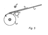
- a measuring head 1 is e.g. grown in a feed table 2 of a sheet-fed rotary printing press. Above him, an infrared light source 3 is arranged, which an IR light with z. B. emits 750 nm and illuminates the measuring head 1. The measuring head 1 becomes the body to be measured. B. a paper sheet 4 covered by a scratch-resistant glass plate 6. Below this is an infrared filter 5, which prevents the influence of extraneous light in the daylight wave range spectrum. According to the invention, a CCD line sensor (charged coupled device) 11 is provided as the measuring element. CCD line sensors exist e.g. from 1728 picture elements arranged in one line. These picture elements are e.g.
- the CCD sensor 11 is e.g. 17.28 mm long and thus has 1728 picture elements, i.e. there are 100 measuring cells per millimeter.
- the CCD line sensor 11 is known to consist of four interacting function groups.
- This area takes up the information available in the light distribution. It consists of 1728fotoemp sensitive image elements that are isolated from one another with the aid of a suitable stop diffusion. The picture elements do not need control electrodes that would hinder the incidence of light. The photons can reach the picture elements directly. Each picture element is separated from the other by a comprehensive potential threshold, so that the charges cannot run into one another.
- the photosensitive area is supplemented at the beginning and at the end by isolation areas, the length of which corresponds to 8 picture elements each, and by 8 covered picture elements adjoining it. These supply a black level current, which is not evaluated in this arrangement.
- An integration element (memory) is assigned to each photosensitive element. That collects the electrons generated by photons. At the end of the integration time, the charges are transferred to a shift register by an applied pulse.
- the charge packets are transported to the output circuit in two shift registers.
- Each of the two shift registers has 879 elements.
- An output gate is located at the end of the shift register, which enables the charge packets to be transferred to the following output stages.
- two impedance converters combined with charge dissipation are provided at the end of two shift registers.
- the incoming charge packets are converted in these output stages into voltage pulses at the output of the line sensor, which are proportional to the amount of charge in the charge packets.
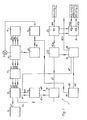
- the oscillator 9, a clock preparation 12, a driver module 13 and a CCD supply 14 supply the CCD sensor 11 with all the necessary clocks 0T 0X, 0R and voltages Vpg, Vei, Vt. e.g.
- a machine synchronization pulse 0EX reaches a logic logic module 18 via a light barrier.
- the logic logic module 18 then reads a counter of an 11-bit counter 19 at the moment of a light / dark transition (see FIG.
- a transmission rate is e.g.
- the clock signals 0T, 0X, 0R necessary for the CCD sensor 11 are, as already mentioned, continuously generated in the clock processor 12 and transmitted to a CCD driver 13 and there to a desired level, e.g. CMOS level implemented.
- 0T, 0X, 0R are clock signals (square-wave pulses) of different frequencies, they are out of phase with each other, 0T being the transport clock signal, 0X the transfer clock signal and ⁇ R the reset clock signal.
- the ⁇ X signal is applied to the transfer gate of the CCD sensor 11 to move the accumulated charge from the image sensor elements to the transport shift register.
- the reset signal 0R is required to switch the counters 10, 19 and CCD sensor 11 to zero.
- the logic logic stage 18 designed as a synchronization stage has the task of generating a memory take-over pulse 0L from the pulses 0T, 0Z and ⁇ EX and delivering it to the memory 22.
- the current-amplified pulses 0T, ⁇ X and 0R in the driver stage 13 reach the CCD sensor 11.
- the supply voltages Vpg, Vei and V are generated by a CCD supply 14 and fed to the CCD sensor 11.
- the position of a body edge is e.g. an arc edge 29 measured on the CCD sensor 11.
- the CCD sensor 11 emits an analog video signal V when illuminated by an IR radiator 3.
- the length and amplitude of this video signal V is a measure of the position of a body edge to be measured, e.g. Sheet edge 29.
- the video signal V is amplified to signal VA in amplifier 21 (FIG. 1). This is then fed to the comparator 26 and a control module 34 for controlling the illuminance of the IR emitter 3.
- the comparator 26 is equipped with at least one upper and lower adjustable switching threshold for the video signal VA and delivers when the set lower video signal level is exceeded during the light / dark transition, i.e. when partially covering the CCD sensor 11, a digital pulse ⁇ Z, which is fed to the synchronization module 18.
- the pulses ⁇ Z, 0T and ⁇ EX are processed to a takeover pulse 0L.
- This pulse 0L activates the memory 22, so that it takes over the counter reading present at the main counter 19 in the memory 22 at an edge of the take-over pulse ⁇ Lden.
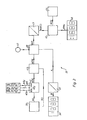
- the counter reading is output from the memory 22 to a display unit 32 by means of the multiplexer 23, which is controlled by a 4-bit binary counter 24 (entire FIG. 2).
- the CCD sensor 11 is irradiated by an infrared light source 3. It is arranged at a short distance above the sensor 11. Since the sensor 11 is sensitive to changes in illuminance and temperature fluctuations. a control module 34 is provided for controlling the illuminance of the light source 3. The voltage level of the video signal V is taken as the actual value, which is compared with an adjustable setpoint corresponding to a certain illuminance. In accordance with the control deviation, the illuminance is controlled by means of a control module 34.
- the display device 32 (FIG. 2) has a preselection switch 36.
- the zero point of the measuring system can be shifted by means of subtraction by means of the preselection switch 36.
- the setting value of the preselection switch 36 corresponding BCD value B is fed to a BCD / binary code converter 37.
- the value A converted from the BCD value B into a binary value A is inverted and fed to a full adder 38.
- the clock frequency 00 required for the data transmission is generated in an oscillator 39.
- the corresponding pulses 00 are fed to a demultiplexer 41 and an intermediate memory 42.
- the demultiplexer 41 generates a synchronizing pulse 0Sy in order to achieve an in-phase nature of the multiplexer 23 (in the measuring head 1) and the demultiplexer 41 in the display unit 32.
- the data 0M arriving from the multiplexer 23 (measuring head 1) serially at the demultiplexer41 are separated in the demultiplexer41 by 16 bits each and are output as ⁇ DE pulses to the buffer store 42 and temporarily stored there. New data overwrite the old one.
- clock signals 0TA are generated in the demultiplexer 41 and fed to the 4-bit counter 24 of the measuring head 1.
- Pulses ⁇ ZW are output from the buffer 42 to the full adder 38 and added with the inverted binary value A of the preselection switch 36.
- the full adder 38 also has a connection (interface) for a computer 40.
- the outgoing binary pulses ⁇ VO added in the full adder 38 are fed to a binary / BCD code converter 43 and are emitted by the latter as a ⁇ BCD pulse to a multiplexer 45 which is driven by an oscillator 44. From the multiplexer 45, pulses ⁇ MU arrive at a digital display device 46, on which the value corresponding to the measured value can be read.
- an external synchronization pulse ⁇ EX must be supplied to the measuring head from the outside.
- a suitable pulse generator is e.g. a fork IR light barrier, or a mechanical button.
- Any zero point can be set via the preselection switch 36 or at e.g. Sheet shifting processes in sheet-fed rotary printing presses, any desired value for the position can be entered.
- each signal or value V, VA or pulse A, B, ⁇ BCD, ⁇ DE, ⁇ EX, 0L, 0M, ⁇ MU, 00, ⁇ OS, 0R, 0S, 0Sy, ⁇ SP, 0T, ⁇ TA, ⁇ TH, ⁇ VO, ⁇ ZW are each transported via a signal line of the same name.
- the multiplexer23 has an output 0M to which the signal line 0M is connected, the counter 24 has the inputs 0Sy and ⁇ TA to which the signal lines ⁇ Sy and ⁇ TA are connected, the demultiplexer41 has the outputs 0Ta, ⁇ Sy and den Input ⁇ M to which the signal lines ⁇ TA, ⁇ Sy and ⁇ M are connected.
Landscapes
- Physics & Mathematics (AREA)
- General Physics & Mathematics (AREA)
- Engineering & Computer Science (AREA)
- Mechanical Engineering (AREA)
- Length Measuring Devices By Optical Means (AREA)
Claims (4)
Priority Applications (1)
| Application Number | Priority Date | Filing Date | Title |
|---|---|---|---|
| AT85115120T ATE50055T1 (de) | 1984-12-04 | 1985-11-28 | Messkopf. |
Applications Claiming Priority (4)
| Application Number | Priority Date | Filing Date | Title |
|---|---|---|---|
| DE3444172 | 1984-12-04 | ||
| DE3444172 | 1984-12-04 | ||
| DE3446531A DE3446531C2 (de) | 1984-12-04 | 1984-12-20 | Einrichtung zur Bestimmung einer Lage einer Kante eines Druckträgers in einer Rotationsdruckmaschine |
| DE3446531 | 1984-12-20 |
Publications (4)
| Publication Number | Publication Date |
|---|---|
| EP0184145A2 EP0184145A2 (fr) | 1986-06-11 |
| EP0184145A3 EP0184145A3 (en) | 1987-02-04 |
| EP0184145B1 EP0184145B1 (fr) | 1990-01-31 |
| EP0184145B2 true EP0184145B2 (fr) | 1994-12-14 |
Family
ID=25827045
Family Applications (1)
| Application Number | Title | Priority Date | Filing Date |
|---|---|---|---|
| EP85115120A Expired - Lifetime EP0184145B2 (fr) | 1984-12-04 | 1985-11-28 | Tête de mesure |
Country Status (3)
| Country | Link |
|---|---|
| US (1) | US4680806A (fr) |
| EP (1) | EP0184145B2 (fr) |
| JP (1) | JPH0765888B2 (fr) |
Families Citing this family (36)
| Publication number | Priority date | Publication date | Assignee | Title |
|---|---|---|---|---|
| ATE67122T1 (de) * | 1986-06-14 | 1991-09-15 | Roland Man Druckmasch | Einrichtung an druckmaschinen mit stelleinrichtungen fuer umfangs-, seiten- und diagonalregister. |
| JPH0799324B2 (ja) * | 1987-07-02 | 1995-10-25 | 富士写真フイルム株式会社 | 接合検査装置 |
| DE3734192A1 (de) * | 1987-10-09 | 1989-04-27 | Menschner Maschf Johannes | Verfahren zum automatischen messen der fadendichte pro laengeneinheit, z. b. cm, von bewegten warenbahnen |
| GB8903051D0 (en) * | 1989-02-10 | 1989-03-30 | Moulin Michel | Precision medium handling device for a recorder |
| US5018207A (en) * | 1989-09-18 | 1991-05-21 | Jack Purdum | Apparatus for objectively grading centering condition of a stamp |
| US5130556A (en) * | 1990-11-07 | 1992-07-14 | Eaton Corporation | Photoelectric fiber thickness and edge position sensor |
| US5220177A (en) * | 1991-06-24 | 1993-06-15 | Harris Instrument Corporation | Method and apparatus for edge detection and location |
| US5347135A (en) * | 1991-06-24 | 1994-09-13 | Harris Instrument Corporation | Method and apparatus employing a linear array IR region radiation devices for locating the position of conveyor transported products |
| US5252991A (en) * | 1991-12-17 | 1993-10-12 | Hewlett-Packard Company | Media edge sensor utilizing a laser beam scanner |
| US5294803A (en) * | 1991-12-30 | 1994-03-15 | Tandberg Data A/S | System and a method for optically detecting an edge of a tape |
| US5244641A (en) * | 1992-04-28 | 1993-09-14 | Phillips Petroleum Company | Absorption of hydrogen sulfide and absorbent composition therefor |
| US5389789A (en) * | 1992-05-20 | 1995-02-14 | Union Camp Corporation | Portable edge crack detector for detecting size and shape of a crack and a portable edge detector |
| JP3056329B2 (ja) * | 1992-06-19 | 2000-06-26 | 富士写真フイルム株式会社 | 読取原稿有無判別方法および装置 |
| US5326983A (en) * | 1993-06-30 | 1994-07-05 | Eastman Kodak Company | Storage phosphor cassette autoloader having cassette sensor |
| US5324957A (en) * | 1993-06-30 | 1994-06-28 | Eastman Kodak Company | Belt position sensor |
| US5546808A (en) | 1994-09-06 | 1996-08-20 | Harris Instrument Corporation | Apparatus and method for binocular measurement system |
| DE19506467A1 (de) * | 1995-02-24 | 1996-08-29 | Koenig & Bauer Albert Ag | Vorrichtung und Verfahren zum Messen einer Lage einer Kante von Bahnen oder Bogen |
| US5729024A (en) * | 1995-05-08 | 1998-03-17 | Ricoh Company, Ltd. | Original edge detecting system and optical sensor |
| DE19543634A1 (de) * | 1995-11-23 | 1997-05-28 | Giesecke & Devrient Gmbh | Vorrichtung und Verfahren zum Vereinzeln von Blattgut aus einem Stapel |
| GB2309298B (en) | 1996-01-16 | 2000-02-23 | Mars Inc | Optical sensing |
| US5867274A (en) * | 1997-02-14 | 1999-02-02 | Harris Instrument Corporation | System for the measurement of the cut length of moving articles |
| AU2909000A (en) * | 1999-02-10 | 2000-08-29 | Nexpress Llc | System for measuring the position of an edge of a transparent article |
| KR100316465B1 (ko) * | 1999-10-30 | 2001-12-12 | 김중권 | 이피씨 빔 센서 장치 |
| US20070165206A1 (en) * | 2004-04-10 | 2007-07-19 | Arnold Olesch | Installation for processing plate-shaped substrates |
| DE102005033759B4 (de) * | 2005-07-15 | 2012-04-12 | Eastman Kodak Company | Verfahren zur Erkennung einer Seitenkante eines semitransparenten Bedruckstoffes in einer Druckmaschine |
| US8029642B2 (en) | 2007-07-27 | 2011-10-04 | The Boeing Company | Tape removal apparatus and process |
| US8345269B2 (en) | 2007-09-22 | 2013-01-01 | The Boeing Company | Method and apparatus for measuring the width of composite tape |
| US7922856B2 (en) * | 2008-01-02 | 2011-04-12 | The Boeing Company | Graphite tape supply and backing paper take-up apparatus |
| US8557074B2 (en) * | 2008-02-27 | 2013-10-15 | The Boeing Company | Reduced complexity automatic fiber placement apparatus and method |
| CN102089475B (zh) | 2008-07-07 | 2012-10-03 | 福伊特专利公司 | 用于在无尽带上产生图案的方法 |
| US8986482B2 (en) * | 2008-07-08 | 2015-03-24 | The Boeing Company | Method and apparatus for producing composite structures |
| DE102008040973A1 (de) * | 2008-08-04 | 2010-02-11 | Voith Patent Gmbh | Verfahren zum Erzeugen eines Musters auf einem Endlosband |
| US20100193103A1 (en) * | 2009-01-31 | 2010-08-05 | The Boeing Company | Automated fiber placement using networked autonomous vehicles |
| US8308101B2 (en) * | 2009-03-09 | 2012-11-13 | The Boeing Company | Simplified fiber tensioning for automated fiber placement machines |
| US8454788B2 (en) * | 2009-03-13 | 2013-06-04 | The Boeing Company | Method and apparatus for placing short courses of composite tape |
| US8146262B1 (en) * | 2009-10-21 | 2012-04-03 | The Boeing Company | Method and device for locating hole center |
Family Cites Families (16)
| Publication number | Priority date | Publication date | Assignee | Title |
|---|---|---|---|---|
| DE2046602B2 (de) * | 1970-09-22 | 1973-09-06 | Koenig & Bauer AG, ,700 Würzburg | Bogenzufuehrung bei druckmaschinen |
| DE2202087A1 (de) * | 1971-02-26 | 1972-09-07 | Polygraph Leipzig | Lichtelektrische Messeinrichtung an bogenbe- und bogenverarbeitenden Maschinen |
| JPS48101960A (fr) * | 1972-04-06 | 1973-12-21 | ||
| DE2460747A1 (de) * | 1974-12-21 | 1976-07-01 | Maschf Augsburg Nuernberg Ag | Vorrichtung zum passergerechten anlegen von bogen in bogenrotationsdruckmaschinen |
| DD125549A1 (fr) * | 1976-03-15 | 1977-05-04 | ||
| DE2808528C3 (de) * | 1978-02-28 | 1981-10-29 | M.A.N. Maschinenfabrik Augsburg-Nürnberg AG, 8900 Augsburg | Bogengreifervorrichtung, bei welcher die Bogengreifer in axialer Richtung bewegbar sind |
| DE2913410C2 (de) * | 1979-04-04 | 1983-08-04 | Koenig & Bauer AG, 8700 Würzburg | Lichtelektrische Meßeinrichtung |
| JPS564003A (en) * | 1979-06-23 | 1981-01-16 | Nippon Kogaku Kk <Nikon> | System for detecting edge of moving body |
| US4309106A (en) * | 1980-02-04 | 1982-01-05 | The United States Of America As Represented By The Secretary Of The Air Force | Beam position locater with photodetector array |
| US4326222A (en) * | 1980-02-11 | 1982-04-20 | Exxon Research & Engineering Co. | Method of and apparatus for facsimile sheet feeding |
| US4317138A (en) * | 1980-02-11 | 1982-02-23 | Exxon Research & Engineering Co. | Method and apparatus for facsimile sheet handling |
| DE3032950C2 (de) * | 1980-09-02 | 1984-02-09 | Elektro-Mechanik Gmbh, 5963 Wenden | Einrichtung zur meßtechnischen Auswertung von Videokamerabildern für Bandkantenregelung |
| DD204685A1 (de) * | 1982-03-29 | 1983-12-07 | Bernd Morgenstern | Einrichtung zur messwertaufnahme an bogen- und bahn- be- sowie verarbeitenden maschinen |
| JPS58211279A (ja) * | 1982-06-03 | 1983-12-08 | Nippon Denso Co Ltd | 情報処理装置 |
| US4559452A (en) * | 1982-06-02 | 1985-12-17 | Fujitsu Limited | Apparatus for detecting edge of semitransparent plane substance |
| JPS5997934U (ja) * | 1982-12-20 | 1984-07-03 | オムロン株式会社 | 紙葉類識別装置 |
-
1985
- 1985-06-17 US US06/745,047 patent/US4680806A/en not_active Expired - Lifetime
- 1985-11-28 EP EP85115120A patent/EP0184145B2/fr not_active Expired - Lifetime
- 1985-12-04 JP JP60271709A patent/JPH0765888B2/ja not_active Expired - Fee Related
Also Published As
| Publication number | Publication date |
|---|---|
| JPS61134610A (ja) | 1986-06-21 |
| EP0184145A3 (en) | 1987-02-04 |
| JPH0765888B2 (ja) | 1995-07-19 |
| EP0184145A2 (fr) | 1986-06-11 |
| US4680806A (en) | 1987-07-14 |
| EP0184145B1 (fr) | 1990-01-31 |
Similar Documents
| Publication | Publication Date | Title |
|---|---|---|
| EP0184145B2 (fr) | Tête de mesure | |
| DE69119843T2 (de) | Videokamera | |
| DE68908851T2 (de) | Videokamera für die Überwachung. | |
| EP0884181B1 (fr) | Procédé de regulation des operations effectuées par une machine d'impression | |
| DE3040963C2 (de) | Anordnung zum Überprüfen von Dokumenten, beispielsweise von Banknoten, auf Echtheit | |
| DE2947958C2 (fr) | ||
| DE2847610C2 (fr) | ||
| DE2624308A1 (de) | Verfahren und vorrichtung zur selbsttaetigen mustererkennung von fluessigkeitsbehaeltern, z.b. flaschen, dosen o.dgl. von variierender groesse und form | |
| DE3586444T2 (de) | Verfahren und schaltung zur digitalen integration von digitalen signalen, insbesondere fuer gammaszintillationskamera. | |
| DE2555975A1 (de) | Einrichtung zum feststellen bzw. ueberwachen der abmessung eines gegebenenfalls bewegten gegenstandes | |
| DE3446531C2 (de) | Einrichtung zur Bestimmung einer Lage einer Kante eines Druckträgers in einer Rotationsdruckmaschine | |
| DE2643481A1 (de) | Einrichtung zum automatischen erkennen einer registerpassmarke | |
| EP1312938A2 (fr) | Elément de détection de rayonnement | |
| EP1635452B1 (fr) | Dispositif pour le mesurage sensitif au temps de transit d'un signal | |
| DD241471A1 (de) | Verfahren und anordnung zur automatischen steuerung von luftbildkameras | |
| DE2946862C2 (de) | Lichtmeßvorrichtung | |
| DE2043881C3 (de) | Fotoelektrische Einrichtung mit einem optischen Zeichenträger, insbesondere für Preisberechnungswaagen | |
| DE3636192C1 (de) | Vorrichtung zur Erfassung des Abbildes von Oberflaechenbereichen laufender Warenbahnen | |
| DE2537089B2 (de) | Anordnung zur messung des unterschiedes zwischen den farben einer farbprobe und eines farbmusters | |
| EP0705515B1 (fr) | Procede et dispositif de synchronisation de la prise de vues monochromes et en couleurs au moyen de capteurs photosensibles de lignes | |
| DE2455407C3 (de) | Vorrichtung zum Scharfeinstellen eines optischen Systems durch Kontraststärkemessung | |
| EP0143165A1 (fr) | Senseur de distance pour mesurer la distance d'un objet proche | |
| DE2623578C2 (de) | Vorrichtung zur automatischen Bestimmung der Größe und Anzahl von Teilchen in einem Teilchenfeld | |
| EP3270183B1 (fr) | Dispositif de compensation de la lumiere ambiante pour un capteur optique soumis a la lumiere ambiante et utile | |
| DE2730499B2 (de) | Infrarot-Ortungssystem |
Legal Events
| Date | Code | Title | Description |
|---|---|---|---|
| PUAI | Public reference made under article 153(3) epc to a published international application that has entered the european phase |
Free format text: ORIGINAL CODE: 0009012 |
|
| AK | Designated contracting states |
Kind code of ref document: A2 Designated state(s): AT BE CH DE FR GB IT LI LU NL SE |
|
| PUAL | Search report despatched |
Free format text: ORIGINAL CODE: 0009013 |
|
| AK | Designated contracting states |
Kind code of ref document: A3 Designated state(s): AT BE CH DE FR GB IT LI LU NL SE |
|
| 17P | Request for examination filed |
Effective date: 19870328 |
|
| 17Q | First examination report despatched |
Effective date: 19881108 |
|
| ITF | It: translation for a ep patent filed | ||
| GRAA | (expected) grant |
Free format text: ORIGINAL CODE: 0009210 |
|
| AK | Designated contracting states |
Kind code of ref document: B1 Designated state(s): AT BE CH DE FR GB IT LI LU NL SE |
|
| REF | Corresponds to: |
Ref document number: 50055 Country of ref document: AT Date of ref document: 19900215 Kind code of ref document: T |
|
| REF | Corresponds to: |
Ref document number: 3575779 Country of ref document: DE Date of ref document: 19900308 |
|
| ET | Fr: translation filed | ||
| GBT | Gb: translation of ep patent filed (gb section 77(6)(a)/1977) | ||
| PLBI | Opposition filed |
Free format text: ORIGINAL CODE: 0009260 |
|
| 26 | Opposition filed |
Opponent name: MAN ROLAND DRUCKMASCHINEN AG Effective date: 19901025 |
|
| NLR1 | Nl: opposition has been filed with the epo |
Opponent name: MAN ROLAND DRUCKMASCHINEN AG |
|
| ITTA | It: last paid annual fee | ||
| EPTA | Lu: last paid annual fee | ||
| PUAH | Patent maintained in amended form |
Free format text: ORIGINAL CODE: 0009272 |
|
| STAA | Information on the status of an ep patent application or granted ep patent |
Free format text: STATUS: PATENT MAINTAINED AS AMENDED |
|
| 27A | Patent maintained in amended form |
Effective date: 19941214 |
|
| AK | Designated contracting states |
Kind code of ref document: B2 Designated state(s): AT BE CH DE FR GB IT LI LU NL SE |
|
| REG | Reference to a national code |
Ref country code: CH Ref legal event code: AEN |
|
| GBTA | Gb: translation of amended ep patent filed (gb section 77(6)(b)/1977) |
Effective date: 19941221 |
|
| EAL | Se: european patent in force in sweden |
Ref document number: 85115120.9 |
|
| ET3 | Fr: translation filed ** decision concerning opposition | ||
| NLR2 | Nl: decision of opposition | ||
| NLR3 | Nl: receipt of modified translations in the netherlands language after an opposition procedure | ||
| ITF | It: translation for a ep patent filed | ||
| REG | Reference to a national code |
Ref country code: GB Ref legal event code: IF02 |
|
| PGFP | Annual fee paid to national office [announced via postgrant information from national office to epo] |
Ref country code: DE Payment date: 20021212 Year of fee payment: 18 |
|
| PGFP | Annual fee paid to national office [announced via postgrant information from national office to epo] |
Ref country code: GB Payment date: 20031027 Year of fee payment: 19 |
|
| PGFP | Annual fee paid to national office [announced via postgrant information from national office to epo] |
Ref country code: FR Payment date: 20031120 Year of fee payment: 19 |
|
| PGFP | Annual fee paid to national office [announced via postgrant information from national office to epo] |
Ref country code: AT Payment date: 20031121 Year of fee payment: 19 |
|
| PGFP | Annual fee paid to national office [announced via postgrant information from national office to epo] |
Ref country code: SE Payment date: 20031124 Year of fee payment: 19 Ref country code: LU Payment date: 20031124 Year of fee payment: 19 Ref country code: CH Payment date: 20031124 Year of fee payment: 19 Ref country code: BE Payment date: 20031124 Year of fee payment: 19 |
|
| PGFP | Annual fee paid to national office [announced via postgrant information from national office to epo] |
Ref country code: NL Payment date: 20031125 Year of fee payment: 19 |
|
| PG25 | Lapsed in a contracting state [announced via postgrant information from national office to epo] |
Ref country code: DE Free format text: LAPSE BECAUSE OF NON-PAYMENT OF DUE FEES Effective date: 20040602 |
|
| PG25 | Lapsed in a contracting state [announced via postgrant information from national office to epo] |
Ref country code: LU Free format text: LAPSE BECAUSE OF NON-PAYMENT OF DUE FEES Effective date: 20041128 Ref country code: GB Free format text: LAPSE BECAUSE OF NON-PAYMENT OF DUE FEES Effective date: 20041128 Ref country code: AT Free format text: LAPSE BECAUSE OF NON-PAYMENT OF DUE FEES Effective date: 20041128 |
|
| PG25 | Lapsed in a contracting state [announced via postgrant information from national office to epo] |
Ref country code: SE Free format text: LAPSE BECAUSE OF NON-PAYMENT OF DUE FEES Effective date: 20041129 |
|
| PG25 | Lapsed in a contracting state [announced via postgrant information from national office to epo] |
Ref country code: LI Free format text: LAPSE BECAUSE OF NON-PAYMENT OF DUE FEES Effective date: 20041130 Ref country code: CH Free format text: LAPSE BECAUSE OF NON-PAYMENT OF DUE FEES Effective date: 20041130 Ref country code: BE Free format text: LAPSE BECAUSE OF NON-PAYMENT OF DUE FEES Effective date: 20041130 |
|
| BERE | Be: lapsed |
Owner name: *KOENIG & BAUER A.G. Effective date: 20041130 |
|
| PG25 | Lapsed in a contracting state [announced via postgrant information from national office to epo] |
Ref country code: NL Free format text: LAPSE BECAUSE OF NON-PAYMENT OF DUE FEES Effective date: 20050601 |
|
| EUG | Se: european patent has lapsed | ||
| REG | Reference to a national code |
Ref country code: CH Ref legal event code: PL |
|
| GBPC | Gb: european patent ceased through non-payment of renewal fee |
Effective date: 20041128 |
|
| PG25 | Lapsed in a contracting state [announced via postgrant information from national office to epo] |
Ref country code: FR Free format text: LAPSE BECAUSE OF NON-PAYMENT OF DUE FEES Effective date: 20050729 |
|
| NLV4 | Nl: lapsed or anulled due to non-payment of the annual fee |
Effective date: 20050601 |
|
| REG | Reference to a national code |
Ref country code: FR Ref legal event code: ST |
|
| BERE | Be: lapsed |
Owner name: *KOENIG & BAUER A.G. Effective date: 20041130 |