EP0185942A2 - Tropfenabgabevorrichtung - Google Patents
Tropfenabgabevorrichtung Download PDFInfo
- Publication number
- EP0185942A2 EP0185942A2 EP85114869A EP85114869A EP0185942A2 EP 0185942 A2 EP0185942 A2 EP 0185942A2 EP 85114869 A EP85114869 A EP 85114869A EP 85114869 A EP85114869 A EP 85114869A EP 0185942 A2 EP0185942 A2 EP 0185942A2
- Authority
- EP
- European Patent Office
- Prior art keywords
- fluid
- drop
- wall
- electroactuator
- nozzle
- Prior art date
- Legal status (The legal status is an assumption and is not a legal conclusion. Google has not performed a legal analysis and makes no representation as to the accuracy of the status listed.)
- Withdrawn
Links
Images
Classifications
-
- B—PERFORMING OPERATIONS; TRANSPORTING
- B41—PRINTING; LINING MACHINES; TYPEWRITERS; STAMPS
- B41J—TYPEWRITERS; SELECTIVE PRINTING MECHANISMS, i.e. MECHANISMS PRINTING OTHERWISE THAN FROM A FORME; CORRECTION OF TYPOGRAPHICAL ERRORS
- B41J2/00—Typewriters or selective printing mechanisms characterised by the printing or marking process for which they are designed
- B41J2/005—Typewriters or selective printing mechanisms characterised by the printing or marking process for which they are designed characterised by bringing liquid or particles selectively into contact with a printing material
- B41J2/01—Ink jet
- B41J2/135—Nozzles
- B41J2/14—Structure thereof only for on-demand ink jet heads
- B41J2/14201—Structure of print heads with piezoelectric elements
- B41J2/14298—Structure of print heads with piezoelectric elements of disc type
-
- B—PERFORMING OPERATIONS; TRANSPORTING
- B05—SPRAYING OR ATOMISING IN GENERAL; APPLYING FLUENT MATERIALS TO SURFACES, IN GENERAL
- B05B—SPRAYING APPARATUS; ATOMISING APPARATUS; NOZZLES
- B05B17/00—Apparatus for spraying or atomising liquids or other fluent materials, not covered by the preceding groups
- B05B17/04—Apparatus for spraying or atomising liquids or other fluent materials, not covered by the preceding groups operating with special methods
- B05B17/06—Apparatus for spraying or atomising liquids or other fluent materials, not covered by the preceding groups operating with special methods using ultrasonic or other kinds of vibrations
- B05B17/0607—Apparatus for spraying or atomising liquids or other fluent materials, not covered by the preceding groups operating with special methods using ultrasonic or other kinds of vibrations generated by electrical means, e.g. piezoelectric transducers
Definitions
- the present invention relates to apparatus for dispensing fluid droplets. More particularly, it concerns an apparatus for dispensing fluid droplets on demand useful in various drop dispensing applications including ink jet printers.
- Devices for the formation and dispensing of fluid droplets on demand typically include a fluid-receiving chamber that is connected to a supply of fluid and to a droplet emitting nozzle or orifice.
- the fluid is perturbed in some way to cause a predetermined volume of the fluid to issue from the nozzle in a drop-wise manner.
- the fluid is exposed directly to an electric or magnetic field to cause drop-wise ejection.
- the volume of the fluid chamber is momentarily reduced to force a predetermined quantity of the fluid through the nozzle.
- the fluid-containing chamber is defined by various wall portions with at least one of the wall portions provided with a measure of flexure.
- An electroactuator typically in the form of a piezoelectric device, is connected to the flexible wall portion so that excitation of the actuator causes the connected wall to flex in such a way that the volume of the fluid chamber is momentarily reduced to force a predetermined quantity of the fluid through the nozzle in a drop-wise manner.
- the flexed wall thereafter returns to its initial position with replacement fluid provided from the supply reservoir.
- U. S. Patent No. 4,245,227, issued January 13, 1981 is directed to an ink jet head having inner and outer cylindrical members wherein only the outer cylindrical member is a piezoelectric element in the case of a single nozzle.
- both inner and/or outer cylindrical members may be piezoelectric members.
- the piezoelectric element vibrates radially when electrically excited to produce vibrations in the ink thereby ejecting the ink through the nozzles. It should be noted that the piezoelectric element is in direct contact with the ink. Such an arrangement requires that the ink be non-conductive.
- U.S. Patent No. 4,387,383, issued June 7, 1983 is directed to a multiple nozzle ink jet head which comprises an array of ink droplet producing devices arranged in a stacked sandwich-like manner.
- the ink jet head comprises a first cavity having a supply of ink and a second cavity which contain a plurality of droplet producing devices in stacked relationship comprising a conductive element, an annular element for containing ink in said second cavity and a transducing element such as a piezoelectric element in contact with the ink.
- the ink is identified as an ink of low conductivity.
- U.S. Patent No. 4,434,430 issued February 28, 1984, is directed to an ink jet head wherein a piezoelectric element is bonded to a planar vibration plate formed of a synthetic resin. Activation of the piezoelectric element flexes the vibration plate normal to its plane thereby displacing ink in the adjacent chamber.
- the piezoelectric element is formed of a high molecular weight piezoelectric material which can double as the vibration plate.
- an apparatus for dispensing fluid droplets includes a plastic resin body having a fluid-receiving chamber defined along a path by at least two spaced apart walls.
- a nozzle is provided in fluid communication with the fluid chamber through which nozzle a predetermined quantity of fluid is ejected in a drop-wise manner.
- An electroactuator having a peripheral surface is connected to one of the walls defining the chamber so that electrical actuation thereof causes a predetermined volume of fluid to pass from the fluid chamber through the nozzle for ejection in the form of a droplet.
- the drop dispenser is fabricated from an injection moldable plastic resin and includes an outer component having a cylindrical wall closed at one end by an end wall to define a counterbore or cavity for coaxially receiving therein an inner component that also includes a cylindrical wall closed at one end by a respective end wall.
- the cylindrical walls of the inner and outer components define therebetween an annular fluid receiving chamber.
- a nozzle is provided in the cylindrical wall of the outer component so that fluid can pass from the annular chamber through the nozzle for drop-wise dispensing.
- An electroactuator in the form of a circular piezoelectric disc is coaxially received within the counterbore or cavity defined by the cylindrical wall of the inner component with the periphery of the disc bonded to the cylindrical wall of the inner component to couple the actuator with the fluid chamber.
- Pulsing the piezoelectric actuator for example, by application of a DC pulse, causes the actuator to undergo radially outward expansion and inward contraction which, in the expansion stage causes a predetermined amount of fluid to be ejected from the nozzle in a drop-wise manner.
- the device of the present invention is particularly well suited for ink jet printers in which droplets of ink are directed in a controlled manner onto a recording media.
- the device of the present invention can be formed from various synthetic plastic resins including glass filled and reinforced resins which can be molded using conventional injection molding techniques.
- a principal objective of the present invention is, therefore, the provision of an improved drop dispensing device that can be manufactured from plastic resins in a straight forward and relatively inexpensive manner compared to prior devices.
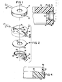
- a drop dispensing apparatus in accordance with the present invention termed herein as a drop dispenser, is illustrated in the various figures and designated generally therein by the reference character 10.
- the drop dispenser 10 in its preferred form is defined as a generally cylindrical body about an axis 12 and includes a nozzle 14, described in more detail below, from which fluid drops 16 are expelled on demand.
- An inlet fluid supply conduit 18 is connected to the drop dispenser 10 for supplying a fluid, such as ink, from an appropriate fluid supply source (not shown).
- the drop dispenser 10 has a nominal ouside diameter of 0.316 inches and an axial height or thickness dimension of 0.100 inches.
- the drop dispenser 10 is assembled from complementary outer and inner components, 20 and 22, an electroactuator 24, and the nozzle 14.
- the outer component 20 is formed symmetrically about the central axis 12 and includes a circular end wall 26 having a concentric bore 28 formed therein.
- a cylindrical wall 30 extends axially from the end wall 26 and terminates with an end surface 32.
- the end wall 26 and the cylindrical wall 30 define a closed-end cavity or counterbore having a nominal inside diameter and depth for receiving the below described inner component 22.
- a radially aligned bore 36 and coaxial counterbore 38 (Fig. 3) are provided in the cylindrical wall 30 for receiving the nozzle 14, and another bore 40 (Fig. 2) is provided for connection to the fluid supply conduit 18.
- a chamfered surface 42 (Fig. 3) is provided on the inner edge of the cylindrical wall 30 to assist in the assembling and sealing of the drop dispenser 10 as explained below.
- the inner component 22, like the outer component 20, is formed symmetrically about the axis 12 and includes a circular end wall 44 having a concentric bore 46 formed therein.
- a raised circular boss or pad 48 is formed adjacent the bore 46 concentrically about the axis 12 and, as described below, assists in locating the electroactuator 24 in the assmbled drop dispenser 10.
- a cylindrical wall 50 extends axially from the circular end wall 44 and terminates in a flat end surface 52.
- the circular end wall 44 has an outside diameter that is less than the inside diameter of the cylindical wall 30 of the outer component 20 so that the inner component 22 can be received in the outer component 20 with a line-to-line or nominal clearance fit between the two.
- the cylindrical wall 50 of the inner component 22 is formed with an outside diameter less than the inside diameter of the cylindrical wall 30 of the outer component 20 so that an annular channel or chamber 54 (Fig. 6) is defined when the inner and outer components 20 and 22 are assembled to one another as described more fully below.
- the flat end surface 52 of the wall 50 is designed to butt against the end wall 26 of the outer component 20 to define the overall length of the annular chamber 54.
- the cylindrical walls 30 and 50 of the outer and inner components 20 and 22 have respective inside and outside diameters of 0.316 and 0.310 inches to provide an annular chamber 54 having a radial thickness dimension of 0.003 inches.
- the wall 50 has an axial length of 0.030 inches to define the axial length of the annular chamber 54.
- the electroactuator 24 (Fig. 2) is defined as a piezoelectric disc formed about the axis 12 and includes a central opening 56 and a circular peripheral surface 58. As explained below, the electroactuator 24 undergoes a radially outward expansion as a result of pulsed electrical excitation.
- the electroactuator 24 is formed at an outside diameter that is nominally equal to the inside diameter of the cylindrical wall 50 of the inner component 22 and has a radial thickness dimension of 0.020 inches, in a preferred embodiment.
- the inside diameter of the cylindrical wall 50 is 0.290 inches and, as mentioned above, the outside diameter is 0.310 to provide an inner wall having a wall thickness in the radial direction of 0.010 inches, this radial thickness being relatively thick compared to those prior devices that have utilized a thin (e.g., 0.001 inch) flexible metallic wall between the actuator and the fluid chamber.
- the electroactuator 24 includes electrodes (not shown) formed on its opposite faces for connection to conductor (not shown) which provide electrical energy for exciting the electroactuator 24 to cause a radially outward expansion.
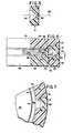
- the nozzle 14 as shown in the cross sectional view of Fig. 5 , is formed cyli-ndrically about a nozzle axis 60 and includes a converging entry port 62 that leads to an exit orifice 64, which has a diameter of 0.002 to 0.003 inches in the case of the preferred embodiment.
- the nozzle 14 is received within the counterbore 38 and can be retained in place with adhesive, solvent-, ultrasonic or similar bonding techniques.
- the inner component 22 and, preferably, the outer component 20 are both fabricated from a plastic resin, including glass-filled plastic resins, that can be molded by injection molding techniques.
- cylindrical wall 50 should have sufficient thickness to be injection molded but should be thin enough so as not to prevent the pulse from the electroactuator 24 from ejecting a drop from nozzle 14.
- Preferred plastics are styrene acrylonitrile as well as 50% glass-filled polyphenylene sulfide, which latter plastic provides desirably rigid outer and inner components.
- a wide range of plastics are likewise suitable including polycarbonate, polystyrene, acrylonitrile/butadiene/styrene.
- the outer and inner components can be fabricated from the same or different matrials. Alternatively, the outer component is fabricated from metal, such as the conventinal metals employed in the manufacture of ink jet printing heads.
- the drop dispenser 10 is assembled by first inserting the circular electroactuator 24 into the counterbore defined by cylindrical wall 50 of the inner component 22 with the electroactuator lying on the locating pad 48 and its circular periphery 58 in engagement with the inside diameter surface of the cylindrical wall 50. Since the electroactuator 24 undergoes both expansion and contraction, it is important that the peripheral surface 58 of the electroactuator 24 and the inside diameter surface of the cylindrical wall 50 be mechanically connected or bonded together. In the preferred embodiment, the peripheral surface 58 of the electroactuator 24 is solvent bonded to the inside diameter surface of the inner wall 50.
- Solvent bonding can be achieved by applying a solvent, such as methyl ethyl ketone in the case of a styrene acrylonitrile plastic, about the interface between the two surfaces to temporarily soften the plastic and allow it to flow into the pores or other interstices of the electroactuator material. When the solvent vaporizes, the plastic rehardens to form a secure mechanical bond, as represented generally by the stippled zone 66 in Fig. 6 between the peripheral surface 58 of the electroactuator 24 2nd the inner wall 50.
- an ultraviolet curable adhesive is employed.
- the electroactuator 24 is not bonded or attached to the locating pad 48 but rests upon and is accurately positioned by the locating pad 48 while the bonding step takes place.
- the inner component 22, with the assembled electroactuator 24, is inserted into the outer component 20 with the chamfered surface 42 functioning to guide the two components together until the flat end surface 52 of the inner wall 50 abuts the circular end wall 26 of the outer component 20 as shown in Fig. 6.
- the end surface 52 of the wall 50 is bonded to the abutting surface of the circular end wall 26 to achieve a fluid-tight seal.
- the bonding which is represented generally by the stippled zone 68 between the end surface 52 and the end wall 26 in Fig. 6, is preferably achieved by ultrasonic bonding, although solvent or adhesive bonding is suitable.
- the cylindrical outside diameter and the inside diameter surfaces of the inner and outer components 22 and 20 can be bonded by solvent or adhesive bonding to achieve a fluid-tight seal, this bond being likewise represented in Fig. 6 by a stippled zone 70 adjacent these surfaces.
- a sealant bead 72 shown in broken line illustrated in Fig. 6) can be provided in the groove (unnumbered) defined between the chamfered surface 42 and the inner member 22 to also effect fluid sealing.
- Electrical connection with the electroactuator 24 can be effected by inserting conductive spring clips or similar devices through the central openings, 28 and 46, to engage the conductive faces of the electroactuator.
- the drop dispenser 10 is supplied through the conduit 18 from a source of ink (not shown) with the ink filling the annular chamber 54 as well as the entry port 62 of the nozzle 14. In the standby state, no ink is ejected from the orifice 64.
- an electrical excitation signal such as a DC pulse of selected amplitude and duration, is applied to the electroactuator 24 to cause it, as illustrated by the arrows 74 in Figs. 6 and 7, to expand radially outward to cause the ejection of a predetermined volume of ink from the orifice 64 in the form of a drop 16 typically having a diameter of 60 to 70 microns.
- a continuous series of drops 16 can be obtained by exciting the electroactuator 24 with recurring pulses at a selected pulse repetition rate.
- the exact mechanism by which drop ejection occurs is not fully understood, since the inner wall 50, which separates the electroactuator 24 from the ink filled annular chamber 54, can be relatively thick and compliant compared to prior devices where it was conventionally believed that a thin wall, typically metal, provided a measure of necessary flexure to permit a reduction in the volume of the ink containing chamber. It will be noted above, that in the preferred embodiment, the thickness of the plastic wall is 10 times as thick as prior art metal walls. It has been found, surprisingly, that the relatively thick, compliant plastic wall does not absorb or cushion the electroactuator expansion but will in fact transmit sufficient force to effect drop ejection.
- the application of an electrical pulse can result in outward radial expansion as described above, or alternatively, outward radial expansion occurs when the original applied electrical voltage is removed.
- the electroactuator would be at rest, in a contracted state, during the period of applied voltage. Removal of the epplied voltage would result in the drop ejection expansion.
- the drop dispenser of the present invention can be molded from relatively inexpensive plastic materials using injection molding techniques which are well-suited for low-cost volume production. Since the inner wall between the periphery of the electroactuator and the annular ink chamber can be relatively thick (e.g. 0.010 inches) compared to prior devices, the wall thickness criticality associated with prior devices, which criticality contributes to manufacturing costs, is reduced with regard to the drop dispensor of the present invention. While the drop dispensing device of the present invention has been disclosed in the context of a drop dispenser for dispensing ink, as can be appreciated, the device is suitable for many other drop dispensing applications including the drop-wise dispensing of various chemicals.
- the inks employed may he of the conductive or non-conductive type.
- a solvent resistant plastic resin will be selected for the parts of the drop dispenser.
Landscapes
- Coating Apparatus (AREA)
- Particle Formation And Scattering Control In Inkjet Printers (AREA)
- Automatic Analysis And Handling Materials Therefor (AREA)
- Nozzles (AREA)
Applications Claiming Priority (2)
| Application Number | Priority Date | Filing Date | Title |
|---|---|---|---|
| US06/686,454 US4550325A (en) | 1984-12-26 | 1984-12-26 | Drop dispensing device |
| US686454 | 1991-04-17 |
Publications (2)
| Publication Number | Publication Date |
|---|---|
| EP0185942A2 true EP0185942A2 (de) | 1986-07-02 |
| EP0185942A3 EP0185942A3 (de) | 1987-04-08 |
Family
ID=24756358
Family Applications (1)
| Application Number | Title | Priority Date | Filing Date |
|---|---|---|---|
| EP85114869A Withdrawn EP0185942A3 (de) | 1984-12-26 | 1985-11-23 | Tropfenabgabevorrichtung |
Country Status (4)
| Country | Link |
|---|---|
| US (1) | US4550325A (de) |
| EP (1) | EP0185942A3 (de) |
| JP (1) | JPS61154948A (de) |
| CA (1) | CA1246022A (de) |
Families Citing this family (56)
| Publication number | Priority date | Publication date | Assignee | Title |
|---|---|---|---|---|
| US4641155A (en) * | 1985-08-02 | 1987-02-03 | Advanced Color Technology Inc | Printing head for ink jet printer |
| USRE35737E (en) * | 1986-07-09 | 1998-02-24 | Vidoejet Systems International, Inc. | Accoustically soft ink jet nozzle assembly |
| US4692776A (en) * | 1986-09-15 | 1987-09-08 | Polaroid Corporation | Drop dispensing device and method for its manufacture |
| US4877745A (en) * | 1986-11-17 | 1989-10-31 | Abbott Laboratories | Apparatus and process for reagent fluid dispensing and printing |
| US4887100A (en) * | 1987-01-10 | 1989-12-12 | Am International, Inc. | Droplet deposition apparatus |
| US4911866A (en) * | 1988-11-25 | 1990-03-27 | The Walt Disney Company | Fog producing apparatus |
| US5152456A (en) * | 1989-12-12 | 1992-10-06 | Bespak, Plc | Dispensing apparatus having a perforate outlet member and a vibrating device |
| GB9001606D0 (en) * | 1990-01-24 | 1990-03-21 | Domino Printing Sciences Plc | Continuous ink jet printer |
| US7628339B2 (en) | 1991-04-24 | 2009-12-08 | Novartis Pharma Ag | Systems and methods for controlling fluid feed to an aerosol generator |
| US6629646B1 (en) * | 1991-04-24 | 2003-10-07 | Aerogen, Inc. | Droplet ejector with oscillating tapered aperture |
| US5938117A (en) * | 1991-04-24 | 1999-08-17 | Aerogen, Inc. | Methods and apparatus for dispensing liquids as an atomized spray |
| US6540154B1 (en) | 1991-04-24 | 2003-04-01 | Aerogen, Inc. | Systems and methods for controlling fluid feed to an aerosol generator |
| US5320250A (en) * | 1991-12-02 | 1994-06-14 | Asymptotic Technologies, Inc. | Method for rapid dispensing of minute quantities of viscous material |
| US6537817B1 (en) | 1993-05-31 | 2003-03-25 | Packard Instrument Company | Piezoelectric-drop-on-demand technology |
| US6521187B1 (en) | 1996-05-31 | 2003-02-18 | Packard Instrument Company | Dispensing liquid drops onto porous brittle substrates |
| US6203759B1 (en) | 1996-05-31 | 2001-03-20 | Packard Instrument Company | Microvolume liquid handling system |
| US5659346A (en) | 1994-03-21 | 1997-08-19 | Spectra, Inc. | Simplified ink jet head |
| JP3176245B2 (ja) * | 1995-03-23 | 2001-06-11 | シャープ株式会社 | インクジェットヘッド |
| US6085740A (en) | 1996-02-21 | 2000-07-11 | Aerogen, Inc. | Liquid dispensing apparatus and methods |
| US5758637A (en) | 1995-08-31 | 1998-06-02 | Aerogen, Inc. | Liquid dispensing apparatus and methods |
| US6205999B1 (en) | 1995-04-05 | 2001-03-27 | Aerogen, Inc. | Methods and apparatus for storing chemical compounds in a portable inhaler |
| US6014970A (en) * | 1998-06-11 | 2000-01-18 | Aerogen, Inc. | Methods and apparatus for storing chemical compounds in a portable inhaler |
| US6782886B2 (en) | 1995-04-05 | 2004-08-31 | Aerogen, Inc. | Metering pumps for an aerosolizer |
| US6083762A (en) * | 1996-05-31 | 2000-07-04 | Packard Instruments Company | Microvolume liquid handling system |
| US5969733A (en) * | 1996-10-21 | 1999-10-19 | Jemtex Ink Jet Printing Ltd. | Apparatus and method for multi-jet generation of high viscosity fluid and channel construction particularly useful therein |
| GB9709462D0 (en) * | 1997-05-09 | 1997-07-02 | Videojet Systems Int | A droplet generator for a continuous stream ink jet print head |
| US6296811B1 (en) * | 1998-12-10 | 2001-10-02 | Aurora Biosciences Corporation | Fluid dispenser and dispensing methods |
| JP3649634B2 (ja) * | 1999-02-09 | 2005-05-18 | 東芝テック株式会社 | インクジェットプリンタヘッド及びその製造方法 |
| EP1080915B1 (de) | 1999-09-03 | 2011-07-20 | Canon Kabushiki Kaisha | Flüssigkeitausstosskopfeinheit |
| US6235177B1 (en) | 1999-09-09 | 2001-05-22 | Aerogen, Inc. | Method for the construction of an aperture plate for dispensing liquid droplets |
| US8336545B2 (en) | 2000-05-05 | 2012-12-25 | Novartis Pharma Ag | Methods and systems for operating an aerosol generator |
| US7100600B2 (en) | 2001-03-20 | 2006-09-05 | Aerogen, Inc. | Fluid filled ampoules and methods for their use in aerosolizers |
| US7971588B2 (en) | 2000-05-05 | 2011-07-05 | Novartis Ag | Methods and systems for operating an aerosol generator |
| MXPA02010884A (es) | 2000-05-05 | 2003-03-27 | Aerogen Ireland Ltd | Aparato y metodo para el suministro de medicamentos al sistema respiratorio. |
| US7600511B2 (en) | 2001-11-01 | 2009-10-13 | Novartis Pharma Ag | Apparatus and methods for delivery of medicament to a respiratory system |
| US6948491B2 (en) | 2001-03-20 | 2005-09-27 | Aerogen, Inc. | Convertible fluid feed system with comformable reservoir and methods |
| US6543443B1 (en) | 2000-07-12 | 2003-04-08 | Aerogen, Inc. | Methods and devices for nebulizing fluids |
| US6546927B2 (en) | 2001-03-13 | 2003-04-15 | Aerogen, Inc. | Methods and apparatus for controlling piezoelectric vibration |
| US6550472B2 (en) | 2001-03-16 | 2003-04-22 | Aerogen, Inc. | Devices and methods for nebulizing fluids using flow directors |
| US6732944B2 (en) | 2001-05-02 | 2004-05-11 | Aerogen, Inc. | Base isolated nebulizing device and methods |
| US6554201B2 (en) | 2001-05-02 | 2003-04-29 | Aerogen, Inc. | Insert molded aerosol generator and methods |
| DK1287904T3 (da) * | 2001-09-03 | 2006-04-03 | Microflow Eng Sa | Forstövningsindretning til væsker |
| US7677467B2 (en) | 2002-01-07 | 2010-03-16 | Novartis Pharma Ag | Methods and devices for aerosolizing medicament |
| WO2003057291A1 (en) | 2002-01-07 | 2003-07-17 | Aerogen, Inc. | Devices and methods for nebulizing fluids for inhalation |
| JP4761709B2 (ja) | 2002-01-15 | 2011-08-31 | エアロジェン,インコーポレイテッド | エアロゾル発生器を作動するための方法およびシステム |
| US6915962B2 (en) | 2002-05-20 | 2005-07-12 | Aerogen, Inc. | Apparatus for providing aerosol for medical treatment and methods |
| US8616195B2 (en) | 2003-07-18 | 2013-12-31 | Novartis Ag | Nebuliser for the production of aerosolized medication |
| US7267121B2 (en) | 2004-04-20 | 2007-09-11 | Aerogen, Inc. | Aerosol delivery apparatus and method for pressure-assisted breathing systems |
| US7946291B2 (en) | 2004-04-20 | 2011-05-24 | Novartis Ag | Ventilation systems and methods employing aerosol generators |
| US7290541B2 (en) | 2004-04-20 | 2007-11-06 | Aerogen, Inc. | Aerosol delivery apparatus and method for pressure-assisted breathing systems |
| NZ563360A (en) * | 2005-05-25 | 2011-04-29 | Aerogen Inc | Aerosolising liquid using an apertured membrane aligned within a peizoelectric ring |
| US20080303644A1 (en) * | 2007-06-07 | 2008-12-11 | Scott Technologies, Inc. | Sounder Assembly for a personal alert safety system |
| US8348177B2 (en) * | 2008-06-17 | 2013-01-08 | Davicon Corporation | Liquid dispensing apparatus using a passive liquid metering method |
| US8662412B2 (en) * | 2008-08-25 | 2014-03-04 | The United States Of America As Represented By The Administrator Of The National Aeronautics And Space Administration | Advanced modified high performance synthetic jet actuator with curved chamber |
| TWI527629B (zh) * | 2014-02-14 | 2016-04-01 | 德技股份有限公司 | 霧化器噴頭 |
| EP2957349A1 (de) * | 2014-06-20 | 2015-12-23 | PARI Pharma GmbH | Aerosolerzeuger und Aerosolabgabevorrichtung mit dem Aerosolerzeuger |
Family Cites Families (7)
| Publication number | Priority date | Publication date | Assignee | Title |
|---|---|---|---|---|
| US3965376A (en) * | 1973-02-07 | 1976-06-22 | Gould Inc. | Pulsed droplet ejecting system |
| US3922622A (en) * | 1974-08-12 | 1975-11-25 | Bell Telephone Labor Inc | Elastic waveguide utilizing an enclosed core member |
| US4068144A (en) * | 1976-09-20 | 1978-01-10 | Recognition Equipment Incorporated | Liquid jet modulator with piezoelectric hemispheral transducer |
| CA1107800A (en) * | 1976-10-12 | 1981-08-25 | Kenneth H. Fischbeck | Coincidence fluid displacement and velocity expression of droplet |
| US4331964A (en) * | 1980-12-11 | 1982-05-25 | International Business Machines Corp. | Dual cavity drop generator |
| US4387383A (en) * | 1981-11-12 | 1983-06-07 | Ncr Corporation | Multiple nozzle ink jet print head |
| US4474326A (en) * | 1981-11-24 | 1984-10-02 | Tdk Electronics Co., Ltd. | Ultrasonic atomizing device |
-
1984
- 1984-12-26 US US06/686,454 patent/US4550325A/en not_active Expired - Fee Related
-
1985
- 1985-06-26 CA CA000485293A patent/CA1246022A/en not_active Expired
- 1985-08-01 JP JP60168696A patent/JPS61154948A/ja active Pending
- 1985-11-23 EP EP85114869A patent/EP0185942A3/de not_active Withdrawn
Also Published As
| Publication number | Publication date |
|---|---|
| EP0185942A3 (de) | 1987-04-08 |
| US4550325A (en) | 1985-10-29 |
| CA1246022A (en) | 1988-12-06 |
| JPS61154948A (ja) | 1986-07-14 |
Similar Documents
| Publication | Publication Date | Title |
|---|---|---|
| US4550325A (en) | Drop dispensing device | |
| US4434430A (en) | Ink jet printer head | |
| EP0021755B1 (de) | Vorrichtung zur Tropfenerzeugung durch Druckimpulse | |
| CA1174516A (en) | Ink jet construction and method of construction | |
| JPH07314665A (ja) | インクジェット記録ヘッド、それを用いた記録装置及び記録方法 | |
| JP3406694B2 (ja) | インクジェットプリントヘッド | |
| KR100208924B1 (ko) | 잉크제트 헤드 접속유닛 및 잉크제트 카트리지 및 그 조립방법 | |
| JP2717609B2 (ja) | 高密度インクジェットプリントヘッド | |
| US6474786B2 (en) | Micromachined two-dimensional array droplet ejectors | |
| US8042916B2 (en) | Micromachined fluid ejector array | |
| JP2769951B2 (ja) | インクジェットプリントヘッドを製造する方法 | |
| US4032928A (en) | Wideband ink jet modulator | |
| US4779099A (en) | Clamp for and method of fabricating a multi-layer ink jet apparatus | |
| US4727379A (en) | Accoustically soft ink jet nozzle assembly | |
| US4387383A (en) | Multiple nozzle ink jet print head | |
| JPH0994952A (ja) | インクジェットヘッド | |
| US4390886A (en) | Ink jet printing machine | |
| KR19990006714A (ko) | 액체 토출 방법 및 액체 토출 헤드 | |
| EP0710182A1 (de) | Tintenstrahlspritzdüsen | |
| KR20020025675A (ko) | 정전기적으로 전환되는 잉크젯 디바이스 및 그 조작 방법 | |
| USRE35737E (en) | Accoustically soft ink jet nozzle assembly | |
| JPS6325943B2 (de) | ||
| JP2002103633A (ja) | フレックステンショナルトランスデューサおよびフレックステンショナルトランスデューサの製造方法 | |
| JPH066373B2 (ja) | インクジエツトヘツド | |
| JPS6234550B2 (de) |
Legal Events
| Date | Code | Title | Description |
|---|---|---|---|
| PUAI | Public reference made under article 153(3) epc to a published international application that has entered the european phase |
Free format text: ORIGINAL CODE: 0009012 |
|
| AK | Designated contracting states |
Kind code of ref document: A2 Designated state(s): DE FR GB |
|
| PUAL | Search report despatched |
Free format text: ORIGINAL CODE: 0009013 |
|
| AK | Designated contracting states |
Kind code of ref document: A3 Designated state(s): DE FR GB |
|
| 17P | Request for examination filed |
Effective date: 19870917 |
|
| 17Q | First examination report despatched |
Effective date: 19881206 |
|
| STAA | Information on the status of an ep patent application or granted ep patent |
Free format text: STATUS: THE APPLICATION IS DEEMED TO BE WITHDRAWN |
|
| 18D | Application deemed to be withdrawn |
Effective date: 19890417 |
|
| RIN1 | Information on inventor provided before grant (corrected) |
Inventor name: VIOLA, MICHAEL S. |