EP0186536A1 - Apparat zum Entfernen von Schlamm für eine Reinigungseinrichtung von einer Dampferzeugerrohrplatte und Dampferzeuger mit solchem Apparat - Google Patents
Apparat zum Entfernen von Schlamm für eine Reinigungseinrichtung von einer Dampferzeugerrohrplatte und Dampferzeuger mit solchem Apparat Download PDFInfo
- Publication number
- EP0186536A1 EP0186536A1 EP85402193A EP85402193A EP0186536A1 EP 0186536 A1 EP0186536 A1 EP 0186536A1 EP 85402193 A EP85402193 A EP 85402193A EP 85402193 A EP85402193 A EP 85402193A EP 0186536 A1 EP0186536 A1 EP 0186536A1
- Authority
- EP
- European Patent Office
- Prior art keywords
- enclosure
- pipe
- plate
- water
- tubes
- Prior art date
- Legal status (The legal status is an assumption and is not a legal conclusion. Google has not performed a legal analysis and makes no representation as to the accuracy of the status listed.)
- Granted
Links
- 238000004140 cleaning Methods 0.000 title claims abstract description 15
- 238000009434 installation Methods 0.000 title claims description 18
- 239000010802 sludge Substances 0.000 title claims description 15
- XLYOFNOQVPJJNP-UHFFFAOYSA-N water Substances O XLYOFNOQVPJJNP-UHFFFAOYSA-N 0.000 claims abstract description 44
- 239000007788 liquid Substances 0.000 claims abstract description 8
- 238000009304 pastoral farming Methods 0.000 claims abstract description 5
- 238000005507 spraying Methods 0.000 claims abstract 2
- 230000000712 assembly Effects 0.000 claims description 12
- 238000000429 assembly Methods 0.000 claims description 12
- 238000002347 injection Methods 0.000 claims description 10
- 239000007924 injection Substances 0.000 claims description 10
- 238000005192 partition Methods 0.000 claims description 7
- 239000012530 fluid Substances 0.000 claims description 3
- 239000007921 spray Substances 0.000 claims description 3
- 230000000149 penetrating effect Effects 0.000 claims 1
- 230000004087 circulation Effects 0.000 description 4
- 238000009826 distribution Methods 0.000 description 3
- 238000010408 sweeping Methods 0.000 description 3
- 238000010586 diagram Methods 0.000 description 2
- 230000037431 insertion Effects 0.000 description 2
- 238000003780 insertion Methods 0.000 description 2
- 241001415961 Gaviidae Species 0.000 description 1
- 238000010276 construction Methods 0.000 description 1
- 229940082150 encore Drugs 0.000 description 1
- 230000002452 interceptive effect Effects 0.000 description 1
- 210000003041 ligament Anatomy 0.000 description 1
- 238000004519 manufacturing process Methods 0.000 description 1
- 210000000056 organ Anatomy 0.000 description 1
- 230000003836 peripheral circulation Effects 0.000 description 1
- 230000002093 peripheral effect Effects 0.000 description 1
- 238000010926 purge Methods 0.000 description 1
- 239000002002 slurry Substances 0.000 description 1
- 125000006850 spacer group Chemical group 0.000 description 1
- 239000000725 suspension Substances 0.000 description 1
- 238000003466 welding Methods 0.000 description 1
Images



Classifications
-
- F—MECHANICAL ENGINEERING; LIGHTING; HEATING; WEAPONS; BLASTING
- F22—STEAM GENERATION
- F22B—METHODS OF STEAM GENERATION; STEAM BOILERS
- F22B37/00—Component parts or details of steam boilers
- F22B37/02—Component parts or details of steam boilers applicable to more than one kind or type of steam boiler
- F22B37/48—Devices or arrangements for removing water, minerals or sludge from boilers ; Arrangement of cleaning apparatus in boilers; Combinations thereof with boilers
- F22B37/54—De-sludging or blow-down devices
-
- F—MECHANICAL ENGINEERING; LIGHTING; HEATING; WEAPONS; BLASTING
- F22—STEAM GENERATION
- F22B—METHODS OF STEAM GENERATION; STEAM BOILERS
- F22B37/00—Component parts or details of steam boilers
- F22B37/02—Component parts or details of steam boilers applicable to more than one kind or type of steam boiler
- F22B37/48—Devices or arrangements for removing water, minerals or sludge from boilers ; Arrangement of cleaning apparatus in boilers; Combinations thereof with boilers
- F22B37/483—Devices or arrangements for removing water, minerals or sludge from boilers ; Arrangement of cleaning apparatus in boilers; Combinations thereof with boilers specially adapted for nuclear steam generators
Definitions
- the present invention relates to sludge removal devices for installation for cleaning the steam generator tubular plate comprising, in a cylindrical enclosure closed by the plate, a bundle of parallel tubes connected to the plate, traversed by a primary fluid to high temperature.
- the invention relates more particularly to the removal devices making it possible to organize, on the plate, a circulation of cleaning liquid by injection of a cleaning liquid, generally water, at the periphery of the plate and under almost incidence grazing and by suction of the water which collects at the periphery of the plate.
- a cleaning liquid generally water
- the installation generally comprises, in addition to the device, at least one lance that can be moved radially between two adjacent plies of tubes, parallel to and near the tubular plate, the lance having a terminal part provided with nozzles directing oblique jets towards the tube plate.
- the document FR-A-2,352,269 describes for example a device which comprises two assemblies which are inserted into the enclosure through a closable hole in the latter. Each assembly consists of two symmetrically and tangentially directed inlet nozzles and two outlet nozzles. Two semi-circular circumferential flows are thus produced at the periphery of the tube plate.
- this device has significant drawbacks.
- the nozzles are introduced through the envelope through the same hole as a lance or lances for attacking deposits on the plate. The whole therefore represents such a bulk that it can only be inserted through a hole of large diameter.
- the present invention aims in particular to provide a device for eliminating sludge for installations for cleaning tubular plates which respond better than those previously known to the requirements of practice, in particular in that it is of simple structure and easy to put in place, and guarantees a good sweeping of the sludges suspended by attack lances of the layer of mud which has gradually formed and hardened during the operation of the generator.
- the invention proposes in particular a device of the type defined above, comprising at least one assembly which can be inserted into the enclosure through a hole located near the tubular plate, said assembly comprising a curved suction pipe which can be inserted into the envelope through the hole and of such shape that it comes to close in the immediate vicinity of the plate, between the enclosure and the bundle of tubes, and a pipe placed inside the pipe, intended to be connected to a cleaning liquid supply, terminated by a water spray nozzle in one direction transverse to the pipe, following a grazing path relative to the tube plate and in the circumferential direction of the enclosure.
- the pipe may end in a projection head crossing the side wall of the pipe; in its current part, the pipe can be held in the pipe by perforated centralizers distributed along the pipe.
- the pipe is advantageously provided with a tight fixing flange on the access hole provided in the envelope.
- a pipe having a rigid end portion and whose permanent curvature is sufficiently high so that this end portion can be engaged through an eye hole until it comes in close proximity to the tube plate, without it abutting against the exchange tubes placed at the periphery of the bundle.
- the thickness of the envelope, the free distance between the beam and the envelope and / or the dimension of the access hole will be such that it will be necessary to constitute the terminal section of the pipe by a flexible. This can have the high radius of curvature required for the introduction, then flex so as to ensure good contact between the outlet of the pipe and the plate at the end of insertion of the pipe. In practice, this flexible section may consist of a bellows.
- the invention is applicable whatever the mesh of the distribution network of the exchange tube in the bundle.
- the device is adaptable to an exchanger whose tubes are distributed in a square network and it can then in particular cooperate with slurry attack lances of the kind described in the document FR-A-2,514,108 already mentioned.
- the device can also be used in a heat exchanger where the tubes are distributed in a triangular network. In this case, it will advantageously be associated with a lance or spears for attacking the sludge in the three directions of the mesh of the network.
- the steam generator shown in FIG. 1 comprises a pressure enclosure of cylindrical shape 1 closed at its lower part by a tubular plate 2 in which are terminated and welded the end parts of U-shaped heat exchange tubes, such as tube 7
- the enclosure is extended, under the plate 2, by a dome delimiting a water box 3, separated by a vertical partition 4 into a compartment where the hot primary water coming from the reactor arrives by a pipe and an outlet compartment d '' where the primary water escapes to the reactor through a tube 6. Between the two compartments the primary water circulates in the U-shaped tubes.
- a secondary envelope 8 Between the bundle of U-shaped tubes 7 and the enclosure 1 is placed a secondary envelope 8.
- the secondary envelope 8 ends above the tubular plate, leaving a space allowing the secondary water and the water. recirculation that descend through the annular space between the enclosure and the envelope to supply the area occupied by the beam, immediately above the tube plate.
- a plate distribution 11 having a central opening 12 is disposed above the tubular plate 2.
- the hot and cold branches of the tubes 7 are separated by a free diametrical zone 13, called "water street" where spacers 14 and a continuous purge ramp 15.
- the enclosure 1 shown has two relatively large diameter holes 17 called “fist holes” located opposite the "water street” and at the level of the distribution plate 11. Two smaller holes, usually called “ eye “, are aligned in a direction perpendicular to that of the" fist holes "at a short distance from the tube plate 2. Often, two" eye holes “16 are also provided below the" fist holes ".
- the enclosure 1 is surrounded by a casemate (not shown) whose role is in particular to stop the parts and projected debris in the event of an incident.
- an installation is generally used having on the one hand means for attacking the layer of mud, comprising at least one lance insertable into the enclosure, and on the other share a removal device.
- the latter comprises several organs insertable into the enclosure through the "eye holes” or the "fist holes”.
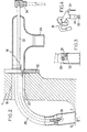
- the insertable assembly shown in Figures 2 to 4 is intended to be introduced into the enclosure 1 through a "trou d'oeil" 16 located 90 * from rue d'eau.
- This assembly 18 consists of a suction pipe 20 provided with a flange 22 intended to be applied in a sealed manner on the enclosure, around the "eye hole", replacing the shutter tape.
- the rear part of this pipe is provided with a suction connector 24 intended to be connected via a hose 26 to a suction pump (not shown).
- the terminal part 28 of the pipe 20 which can be inserted into the enclosure has a shape such that at the same time it can be introduced without jamming against the bore of the "eye hole” or coming into abutment against the exchange tubes and, when it is in place, it bears against the tube plate 2.
- the end of the pipe 20 is advantageously swollen and provided with terminal fingers 30 such that the outlet of the pipe is slightly immersed in the layer of water which will cover the peripheral part of the plate during operation.
- the assembly 18 also comprises means for circulating the water on the plate, comprising a rigid pipe 32 held coaxially with the pipe by perforated centralizers not shown.
- the rear part of the piping 32 projects from the pipe and is provided with a nozzle 34 for connection to a hose for supplying water under high pressure (300 bars for example).
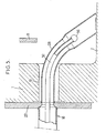
- the downstream end of the piping 32 opens into a nozzle or water spray head 36 which may have the constitution shown in FIG. 3.
- This nozzle is provided with a nozzle 38 for forming a jet directed approximately perpendicularly. to the nozzle, in the circumferential direction of the enclosure.
- the jet emitted must be under grazing incidence. In practice an angle of about 80 'on the vertical will generally be appropriate.
- FIGS. 2 to 4 two sets of the type shown in FIGS. 2 to 4 will be inserted by opposite "eye holes" in the enclosure, the nozzles being oriented with so as to cooperate to organize a circumferential circulation in the same direction over the entire periphery of the plate.
- Figures 7 and 8 show an installation comprising a device for removing sludge with two assemblies 18 connected to a hydraulic system which can be carried by a vehicle so as to be transportable as a block from one steam generator to another.
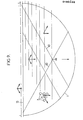
- FIG. 7 shows the use of two lances introduced by "eye holes” 16 placed in the water street. Each of these lances is movable along its axis by a servo motor assembly 42 fixed on a "eye hole” flange. Each of these servomotors is controlled, from the system, in synchronism with the water supply to the lances, so that there is a sequence of sending jets in each of the ligaments (intradubular spaces) of the bundle of tubes 7.
- the lances may have one of the constitutions described in the patent applications already mentioned. They can be composed of a head and tubular sections connectable to each other, for quick assembly and disassembly.
- FIG. 8 shows, for example, the case where shots are fired at angles ranging from 25 'to 85 * in succession.
- the installation can be completed by additional suction pipes introduced through these holes. It is not necessary to describe here the operation of the installation which is carried out according to a cycle similar to that of which a description is given in the document FR-A-2,514,108 already mentioned.
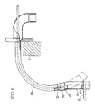
- FIG. 6 shows an assembly constituting yet another embodiment, usable when the curvature which it is necessary to give to the nozzle 28 to avoid interfering with the bundle of tubes is incompatible with the coming of the outlet bearing on the tubular plate .
- the end portion of la.pipe 28 is no longer constituted by a rigid tube, but by a deformable bellows 44.
- This bellows is connected by welding to a nozzle 46 screwed into the terminal bulge of the pipe, bulge which is crossed by the nozzle 36.
- the bellows has the outline indicated in solid lines in FIG. 6, it makes it possible to introduce the pipe into the enclosure 1.
- This bellows can take the form indicated in dashes for come to rest by fingers 30 of an end crown on the plate 2.
- the use of a compressible bellows has the additional advantage of making it possible to use the same assembly for steam generators having variable distances between " eye hole "and” tube plate ".
- FIGs 7 and 8 The installation shown in Figures 7 and 8 is intended to be implemented in a steam generator where the tubes are distributed in a square or at least rectangular network. However, the invention is also applicable to the case of a generator where the tubes are distributed along a triangular mesh.
- Figure 9 very schematically shows the relative arrangement of some tubes 7 in this case.
- the lance introduced by the water street 13 must then direct jets in the three directions indicated by arrows. For this it suffices to have a lance comprising nozzles directed in the appropriate directions.
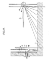
- FIGS. 10A-10D and 11 show how this type of sludge attack can be achieved by an appropriate arrangement of the nozzles 46-52, only the axes of which are shown in FIGS. 10A to 10D.
- FIG. 11 also shows an assembly 18 introduced by an "eye hole" 16.
- Four assemblies of this kind can be introduced through the enclosure 1. It is also possible to provide only two complete assemblies 18 comprising a projection nozzle d water, the other two assemblies ensuring only suction. We can even provide only the suction by counting on the jets projected by the lances 40 to ensure the sweeping.
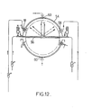
- Figure 12 shows a sludge removal device for a triangular mesh beam generator, of a type having a preheater which divides the base of the abutment into two half-beams (top and bottom of the figure ) separated by a central partition 56 and a skirt 54.
- the device comprises two lances 40 of the type shown in FIG. 11, introduced by two opposite fist holes 17.
- Each of these assemblies 18 (only one of which is shown) is associated with an assembly 58 which ensures only the suction of water loaded with mud.
- Two double nozzles 60 introduced through eye holes, 90 'from the lances, open into the space between the enclosure 1 and the skirt 2 and make it possible to inject water under high pressure for cleaning this space. . The water thus introduced is taken up by the assemblies 18 and 58.
- the general constitution of the spears may be one of those described above.
- a hole allowing high-pressure water to escape upwards will be provided to balance the forces exerted on the lance.
Landscapes
- Engineering & Computer Science (AREA)
- Physics & Mathematics (AREA)
- Thermal Sciences (AREA)
- Mechanical Engineering (AREA)
- General Engineering & Computer Science (AREA)
- High Energy & Nuclear Physics (AREA)
- Cleaning In General (AREA)
- Cleaning By Liquid Or Steam (AREA)
- Treatment Of Sludge (AREA)
- Sewage (AREA)
Applications Claiming Priority (2)
| Application Number | Priority Date | Filing Date | Title |
|---|---|---|---|
| FR8417289A FR2573179B1 (fr) | 1984-11-13 | 1984-11-13 | Dispositif d'enlevement des boues pour installation de nettoyage de la plaque tubulaire d'un generateur de vapeur et installation comportant un tel dispositif |
| FR8417289 | 1984-11-13 |
Publications (2)
| Publication Number | Publication Date |
|---|---|
| EP0186536A1 true EP0186536A1 (de) | 1986-07-02 |
| EP0186536B1 EP0186536B1 (de) | 1990-01-03 |
Family
ID=9309537
Family Applications (1)
| Application Number | Title | Priority Date | Filing Date |
|---|---|---|---|
| EP85402193A Expired - Lifetime EP0186536B1 (de) | 1984-11-13 | 1985-11-13 | Apparat zum Entfernen von Schlamm für eine Reinigungseinrichtung von einer Dampferzeugerrohrplatte und Dampferzeuger mit solchem Apparat |
Country Status (9)
| Country | Link |
|---|---|
| US (1) | US4653435A (de) |
| EP (1) | EP0186536B1 (de) |
| JP (1) | JPS61180807A (de) |
| KR (1) | KR860004272A (de) |
| CA (1) | CA1237349A (de) |
| DE (1) | DE3575193D1 (de) |
| FR (1) | FR2573179B1 (de) |
| YU (1) | YU45991B (de) |
| ZA (1) | ZA858482B (de) |
Cited By (1)
| Publication number | Priority date | Publication date | Assignee | Title |
|---|---|---|---|---|
| EP0265549A1 (de) * | 1986-10-30 | 1988-05-04 | Anco Engineers Inc. | Druckpulsierendes Reinigungsverfahren für einen Rohrbündelwärmetauscher |
Families Citing this family (9)
| Publication number | Priority date | Publication date | Assignee | Title |
|---|---|---|---|---|
| FR2558747B1 (fr) * | 1984-01-27 | 1986-07-25 | Innus Ind Nuclear Service | Procede de nettoyage sous haute pression d'un evaporateur et installation utilisee dans ce but |
| US4848278A (en) * | 1985-11-26 | 1989-07-18 | Apex Technologies, Inc. | Nuclear steam generator sludge lancing method and apparatus |
| BE905193A (nl) * | 1986-07-29 | 1986-11-17 | Smetjet N V | Inrichting voor het met een waterstraal reinigen van een stoomgenerator. |
| JPS63270453A (ja) * | 1987-04-24 | 1988-11-08 | Hitachi Chem Co Ltd | 窒化アルミニウム基板の金属化法 |
| JPS646536U (de) * | 1987-07-01 | 1989-01-13 | ||
| ES2017781B3 (es) * | 1987-11-11 | 1991-03-01 | Siemens Ag | Productor de vapor |
| US4972804A (en) * | 1989-04-25 | 1990-11-27 | Alexander T. Kindling | Method and apparatus for organizing the flow of fluid in a vertical steam generator |
| FR2858683B1 (fr) * | 2003-08-07 | 2005-11-04 | Framatome Anp | Echangeur de chaleur et en particulier generateur de vapeur a fond convexe |
| DE102010039413B4 (de) * | 2010-08-17 | 2012-03-29 | Areva Np Gmbh | Verfahren und Vorrichtung zur Entnahme einer Probe aus einem Dampferzeuger |
Citations (2)
| Publication number | Priority date | Publication date | Assignee | Title |
|---|---|---|---|---|
| FR2099241A5 (de) * | 1970-06-19 | 1972-03-10 | Foster Wheeler Corp | |
| EP0084867A1 (de) * | 1982-01-25 | 1983-08-03 | Kraftwerk Union Aktiengesellschaft | Rohrgassen-Manipulator zum Hochdruck-Abschlämmen von Wärmetauschern |
Family Cites Families (3)
| Publication number | Priority date | Publication date | Assignee | Title |
|---|---|---|---|---|
| DE2262151A1 (de) * | 1972-12-19 | 1974-07-04 | Siemens Ag | Dampferzeuger, insbesondere fuer druckwasserreaktoren |
| FR2514108B1 (fr) * | 1981-10-06 | 1986-06-13 | Framatome Sa | Procede et dispositif d'elimination des boues sur la plaque tubulaire des generateurs de vapeur |
| US4526135A (en) * | 1984-02-03 | 1985-07-02 | Westinghouse Electric Corp. | Eddy current workpiece positioning apparatus |
-
1984
- 1984-11-13 FR FR8417289A patent/FR2573179B1/fr not_active Expired
-
1985
- 1985-11-01 CA CA000494397A patent/CA1237349A/en not_active Expired
- 1985-11-05 ZA ZA858482A patent/ZA858482B/xx unknown
- 1985-11-06 US US06/795,556 patent/US4653435A/en not_active Expired - Fee Related
- 1985-11-12 YU YU176685A patent/YU45991B/sh unknown
- 1985-11-13 JP JP60254607A patent/JPS61180807A/ja active Pending
- 1985-11-13 KR KR1019850008457A patent/KR860004272A/ko not_active Withdrawn
- 1985-11-13 DE DE8585402193T patent/DE3575193D1/de not_active Expired - Lifetime
- 1985-11-13 EP EP85402193A patent/EP0186536B1/de not_active Expired - Lifetime
Patent Citations (2)
| Publication number | Priority date | Publication date | Assignee | Title |
|---|---|---|---|---|
| FR2099241A5 (de) * | 1970-06-19 | 1972-03-10 | Foster Wheeler Corp | |
| EP0084867A1 (de) * | 1982-01-25 | 1983-08-03 | Kraftwerk Union Aktiengesellschaft | Rohrgassen-Manipulator zum Hochdruck-Abschlämmen von Wärmetauschern |
Cited By (1)
| Publication number | Priority date | Publication date | Assignee | Title |
|---|---|---|---|---|
| EP0265549A1 (de) * | 1986-10-30 | 1988-05-04 | Anco Engineers Inc. | Druckpulsierendes Reinigungsverfahren für einen Rohrbündelwärmetauscher |
Also Published As
| Publication number | Publication date |
|---|---|
| YU176685A (en) | 1989-02-28 |
| FR2573179A1 (fr) | 1986-05-16 |
| FR2573179B1 (fr) | 1987-02-13 |
| KR860004272A (ko) | 1986-06-20 |
| DE3575193D1 (de) | 1990-02-08 |
| CA1237349A (en) | 1988-05-31 |
| JPS61180807A (ja) | 1986-08-13 |
| YU45991B (sh) | 1992-12-21 |
| US4653435A (en) | 1987-03-31 |
| ZA858482B (en) | 1986-06-25 |
| EP0186536B1 (de) | 1990-01-03 |
Similar Documents
| Publication | Publication Date | Title |
|---|---|---|
| EP0186536B1 (de) | Apparat zum Entfernen von Schlamm für eine Reinigungseinrichtung von einer Dampferzeugerrohrplatte und Dampferzeuger mit solchem Apparat | |
| FR2585107A1 (fr) | Accouplement pour tuyau cannele | |
| FR2940398A1 (fr) | Obturateur d'une ouverture d'une tubulure de jonction d'une enceinte et d'une canalisation, notamment d'un generateur de vapeur d'un reacteur a eau sous pression | |
| CA2198936C (fr) | Dispositif destine a etre fixe de facon etanche sur au moins un element cylindrique | |
| EP0780627A1 (de) | Verfahren und Vorrichtung zur Reinigung der Endplatte eines Wärmetauschers vom Innern des Wärmetauscherbündels | |
| EP0786638B1 (de) | Wärmetauscher und Maschine zum Zusammenbau eines solchen Wärmetauschers | |
| EP1803996B1 (de) | Interventionsverfahren und Vorrichtung in einem Wasserkasten eines Wärmetauschers | |
| EP0631089A1 (de) | Vorrichtung zum Entfernen von Ablagerungen von dem Rohrboden eines Dampferzeugers | |
| FR2492179A1 (fr) | Appareil pour elargir le sol autour et le long d'un cable enterre a remplacer, procede de remplacement d'un tel cable et procede pour liberer un cable enterre a remplacer | |
| FR2723634A1 (fr) | Dispositif de nettoyage par jet de liquide d'une plaque tubulaire d'un echangeur de chaleur et utilisation. | |
| FR2651869A1 (fr) | Chaudiere electrique a turbulence cyclonique. | |
| EP0634607B1 (de) | Dampferzeuger mit abnehmbarem Zyklonabscheidersystem | |
| EP0782239A1 (de) | Verfahren und Vorrichtung zur Wiederherstellung der Dichtheit eines Verbindungsgliedes wie Wasserkammern in Generatoren mit Wasser/Wasserstoff gemischter Kühlung | |
| EP0673039B1 (de) | Vorrichtung zur Halterung eines Leitrohrs in einem Kernbrennstabbündel | |
| FR2606296A1 (fr) | Rampe de pulverisation d'un fluide | |
| EP0540439A1 (de) | Verdampfungsbefeuchter | |
| EP0622496B1 (de) | Verfahren zur Herstellung eines Mannloches | |
| EP0877222A2 (de) | Anlage zum Druckspritzen von Fluiden in einem Plattenwärmetauscher und Verfahren zur Reinigung dieser Druckspritzanlage | |
| FR2698713A1 (fr) | Dispositif et procédé de nettoyage d'un conduit et notamment d'un tube de guidage d'instrumentation d'un réacteur nucléaire. | |
| EP1998110A2 (de) | Vorrichtung und Verfahren zum Abdichten einer Öffnung in der Strahlenhülle eines Dampfgenerators eines Druckwasserkernreaktors | |
| EP0210899B1 (de) | Entfernbare Abdeckplatte für eine Öffnung, die nur über einen engen Zugang zugänglich ist | |
| FR2761140A1 (fr) | Tete de lance pour nettoyer un generateur de vapeur | |
| EP0238412B1 (de) | Verfahren und Vorrichtung zum Ausführen von Arbeiten an einem im Betrieb befindlichen Gasrohr | |
| WO1999045333A1 (fr) | Dispositif de nettoyage d'un canal dans un echangeur de chaleur a plaques | |
| BE1003464A6 (fr) | Procede et dispositif de nettoyage d'un reservoir. |
Legal Events
| Date | Code | Title | Description |
|---|---|---|---|
| PUAI | Public reference made under article 153(3) epc to a published international application that has entered the european phase |
Free format text: ORIGINAL CODE: 0009012 |
|
| AK | Designated contracting states |
Kind code of ref document: A1 Designated state(s): BE CH DE GB IT LI SE |
|
| 17P | Request for examination filed |
Effective date: 19861013 |
|
| 17Q | First examination report despatched |
Effective date: 19870924 |
|
| GRAA | (expected) grant |
Free format text: ORIGINAL CODE: 0009210 |
|
| AK | Designated contracting states |
Kind code of ref document: B1 Designated state(s): BE CH DE GB IT LI SE |
|
| ITF | It: translation for a ep patent filed | ||
| REF | Corresponds to: |
Ref document number: 3575193 Country of ref document: DE Date of ref document: 19900208 |
|
| GBT | Gb: translation of ep patent filed (gb section 77(6)(a)/1977) | ||
| PLBE | No opposition filed within time limit |
Free format text: ORIGINAL CODE: 0009261 |
|
| STAA | Information on the status of an ep patent application or granted ep patent |
Free format text: STATUS: NO OPPOSITION FILED WITHIN TIME LIMIT |
|
| 26N | No opposition filed | ||
| ITTA | It: last paid annual fee | ||
| PGFP | Annual fee paid to national office [announced via postgrant information from national office to epo] |
Ref country code: DE Payment date: 19940127 Year of fee payment: 9 |
|
| PGFP | Annual fee paid to national office [announced via postgrant information from national office to epo] |
Ref country code: GB Payment date: 19941108 Year of fee payment: 10 |
|
| PGFP | Annual fee paid to national office [announced via postgrant information from national office to epo] |
Ref country code: SE Payment date: 19941121 Year of fee payment: 10 Ref country code: CH Payment date: 19941121 Year of fee payment: 10 |
|
| PGFP | Annual fee paid to national office [announced via postgrant information from national office to epo] |
Ref country code: BE Payment date: 19941123 Year of fee payment: 10 |
|
| EAL | Se: european patent in force in sweden |
Ref document number: 85402193.8 |
|
| PG25 | Lapsed in a contracting state [announced via postgrant information from national office to epo] |
Ref country code: DE Effective date: 19950801 |
|
| PG25 | Lapsed in a contracting state [announced via postgrant information from national office to epo] |
Ref country code: GB Effective date: 19951113 |
|
| PG25 | Lapsed in a contracting state [announced via postgrant information from national office to epo] |
Ref country code: SE Effective date: 19951114 |
|
| PG25 | Lapsed in a contracting state [announced via postgrant information from national office to epo] |
Ref country code: LI Effective date: 19951130 Ref country code: CH Effective date: 19951130 Ref country code: BE Effective date: 19951130 |
|
| BERE | Be: lapsed |
Owner name: FRAMATOME Effective date: 19951130 |
|
| GBPC | Gb: european patent ceased through non-payment of renewal fee |
Effective date: 19951113 |
|
| REG | Reference to a national code |
Ref country code: CH Ref legal event code: PL |
|
| EUG | Se: european patent has lapsed |
Ref document number: 85402193.8 |